The Process
This is the group website for a more completed version.
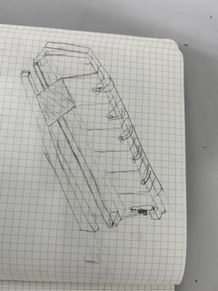
The Idea
Originally, we wanted to make a resin mixing machine. The main principle was that it will be the shape of a box and have 2 cups on each side, and in each cup the user will pour in table Epoxy Part A and B, respectively. Then, in the middle of the machine, towards the bottom, there will be a bottle sitting on a XY track system that closely resembles one found in a 3D printer:
The bottle at the bottom will move on the track and locate itself directly under one of the cups. Then, a pump will pump the resin from the cup on the top of the machine down into the bottle. It will do the same for the other cup. Finally, a mixer will lower itself into the bottle thoroughly mix the resin in the cup.
Pump Research
I was tasked with coming up with a pump model that could pump the resin from the cups down to the bottle itself.
From the tabletop epoxy resin data sheet, Dylan Ferro found that the viscosity of resin is 11,000 cp (centipoise). This means that the resin is very viscous and the pump needs a lot of power in order to pump the resin from the cup.
Then, I found this video, which showed a person using a peristaltic-like manual device to pump out epoxy. But Dylan pointed out that the peristaltic pump would not work because a 0.5 inch tube would be under a lot of pressure, and the whole pump has to be made out of metal, so then we need to find something else that works.
I also found this website where someone used pumps to create a resin tap, much like a viscous water dispenser. But, it involves using a valve (solenoid) and many buttons, which was not convenient at all.
Idea change
Due to the difficulty of finding viable pumps, we decided to change the idea for our project.
This is the new design, drawn by Stuart Christhilf:
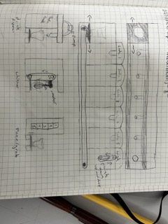
Our new idea is a soda dispenser. When the user presses a button on the left, a cup will move under several tubes poking out of soda bottles. Then, each soda’s pump will dispense a certain amount of soda, before the cup moves to the right and the soda is mixed.
I will discuss how I made the holder for the pumps, the mixing device, and an extension for the mixing motor.
Final Pump Model
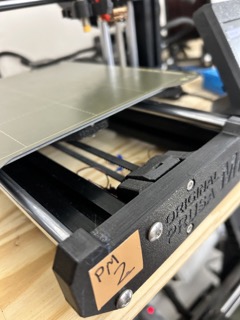
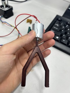
We settled on this pump model:
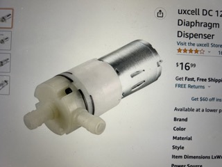
It is just tubes attached to a regular DC motor, and it was compatible with water, which we tested with it:
The water flowed out smoothly, and we found that the optimal range for the pump is around 9 volts (it is a 5-12 volt pump).
The pumps will go on top fo the machine (refer to Stuart’s sketch).
Designing a Pump Holder
Next, I have to design a pump holder for the individual pumps, as they need to stay in place.
In order to model it realistically, I first made a bottle in Fusion360:
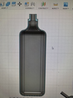
This is a cross section of the bottle, which is just a box extrusion with a neck on top of it.
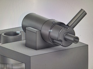
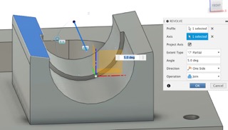
Next, I designed a model pump by first developing the shaft of the pump:
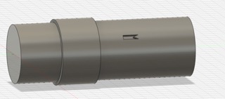
The band in the middle is made using an emboss. Then, I made the 3 inverted arcs at the head of the pump:
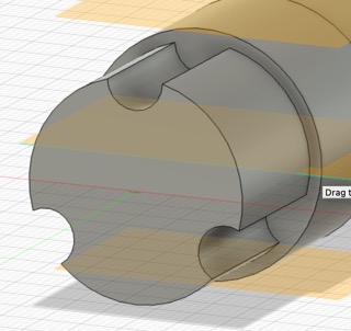
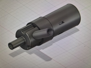
The tubes on the pump are also made using emboss and extrusion. The one on the side is made first by creating a plane that was tangent to the pump, and then extruding a sketch on that plane.
Then, I made a model wall on top of the bottle, in which the bottle’s top will poke out from above a hole:
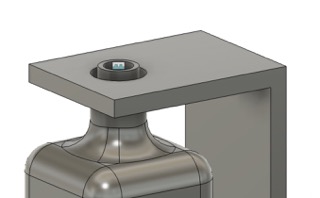
To make putting the bottle inside the wall a bit easier, I made an opening in the wall and tried to put the motor on top of the opening of the bottle:
Dylan pointed out to me that the carbonation from the soda might interfere with the pump, and so I probably had to put the pump on its side instead of putting it straight up from the bottle.
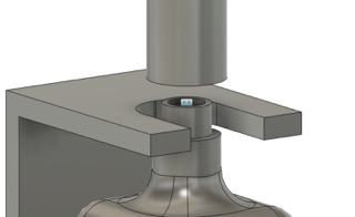
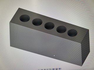
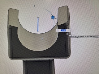
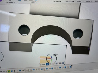
I then deleted the wall and just made a platform above the bottle, and made a similar-looking arc from the side of the board in order for the bottle to slide in from the right side.
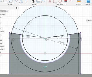
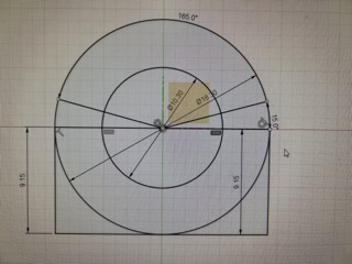
Next, it was time to make the C-clip to press fit the motor. It is basically an arc that partially encloses itself above its bottom hemisphere. Below are the dimensions for the 2D sketch of the C-clip, determined from measuring the size of the pump:
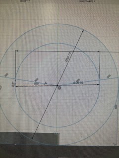
As you can see, I made concentric circles with lines going across them. They are rotated 5 degrees above the halfway diameter to give the C-clip strength.
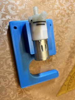
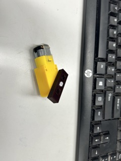
Then, I just extruded c-clip in order to make it 3D. This is the finished product:
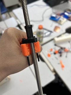
I printed the piece out and tested how well the motor will hold:
I found that it didn’t held the pump very tight, and so I made an addition to my design. Notice that the metal part of the pump has a smaller diameter than the white plastic part. So, I made a small c-clip behind the original one:
Then, I extruded it based on the length of the plastic part. I decided to also rotate the side a bit more upwards.
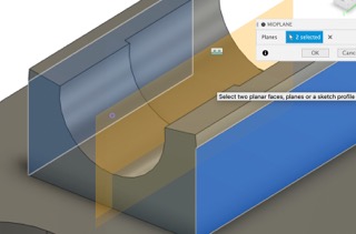
So, I first made a midpoint plane between the two sides of the C-clip, and drew a line on it. Then selected the top of the two sides and selected that line as my rotating axis:
Then, Stuart printed out that I had to make a gap underneath the pump holder in order to fit the wood/acrylic.
I also made 1 inch deep 5 mm holes in order to put the screws into the print and secure it against the wood:
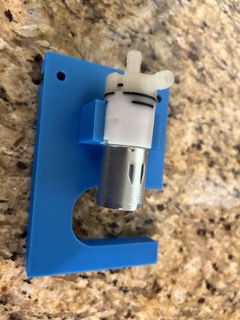
I printed the second version out and it did fit better than the first version:
I printed out a couple more pump holders for the other soda cans later on.
Soldering the Pumps
I also helped to solder wires onto the pumps themselves:
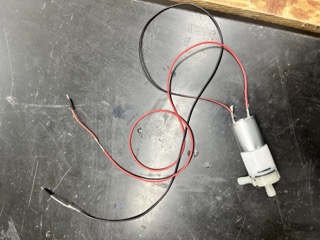
The shredded core wires are soldered to the pump, and their other ends are twisted with the regular jumper wires and soldered together.
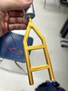
Designing the Mixer
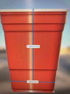
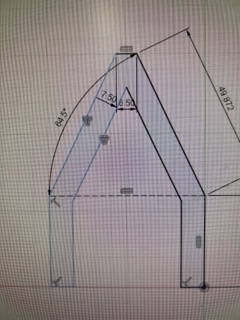
Next, it is time to design the mixer that is going to mix the soda drinks together. First, I took into account the dimensions of the red party cups that we are using:
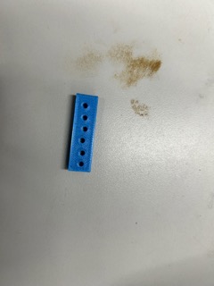
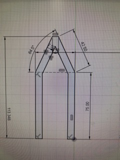
I drew the 2D sketch for the mixer, which resembles a tuning fork:
The top of the mixer is going to go into the motor, so the sizing of the hole was important. At first, we planned to use a high-torque, low speed motor.
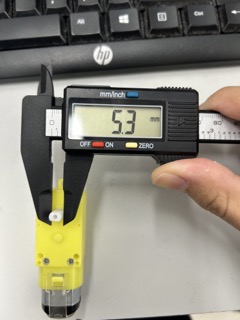
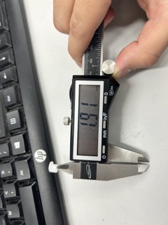
I measure the size and width of the motor that is used for mixing the drinks together:
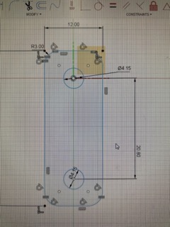
Then, I made a Fusion360 sketch of a series of different hole sizes in order to see which one would fit the best:
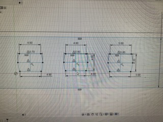
The above image shows the dimensions.
It looks like the middle hole fits the motor best.
Motor Change
However, just as I was about to input the correct dimensions on to the tuning fork, we changed the motor model for mixing the drinks, and I had to repeat the process again.
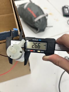
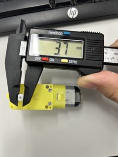
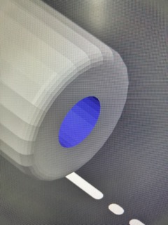
This motor has a plastic part that fits into the hole perfectly, and I measured the inside diameter of it:

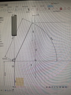
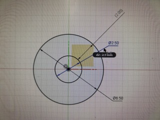
Since I knew that the diameter won’t likely be perfect, I designed a series of different sizes in order to determine the correct size:
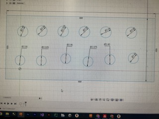
I settled on the final size of 2.50 mm:
This is the final version of the fork:
I printed out the tuning fork, although it didn’t have supports. The result was that the hole was a bit squished, and it didn’t really fit into the mixing motor, due to the elliptical shape of the hole:
As you can see in the picture, it takes a lot of strength to force the tunning fork into hte motor, so the first version of it was impractical.
Also, I found that the mixer was too short and Stuart suggested that it reach 3-4 cm above the top of the cup.
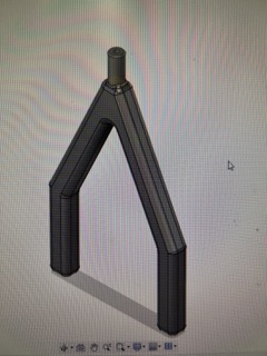
So, I made my second version longer:
I also generated a support around the hole of this fork by first using the paint on support feature in the PrusaSlicer software:
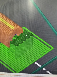
I printed out the second tuning fork, which also had horizontal beams to avoid flimsiness. And its top fits into the 5 volt mixer motor.
Designing the Extension for the Mixer
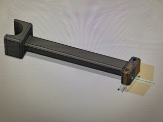
Next, I have to design an extension that holds the mixer motor.
On the right side of the machine, there will be a mechanism for mixing the drinks. A 5 volt motor (the one seen in the last picture above) will be attached to a Z track controlled by a stepper motor. The stepper motor will be able to control the height of the motor, which holds the mixer, which goes into the red cup.
The extension of for the motor is needed as the mixer is actually at the center of the X - track, which Ginny, Daryiah, and Dylan built. Since this track has a certain width, the extension had to be 150mm long in order to reach the cup.
First, I made a 2D sketch for the C-clip of the mixer motor:
The extrusion process of the C-clip is similar to that of the pump holder (using a mid-plane and the rotation tool).
After extruding the press fit, I made the other side of the extension. I had to include holes in this part because there screws are needed to attach the extension to the vertical axis:
I extruded that piece and the final product is this:
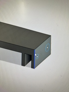
However, I failed to consider one aspect of the vertical axis. There was a protrusion on it which made the screws unable to go through the screw holes in the extension piece.
So, I had to remove a portion of the end piece, which I achieved after extruding an arc:
Now, the end piece was able to fit into the Z-axis:
Acrylic Trouble
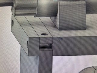
When I made the pump holders, I left a gap in the front of it in order to affix it to the machine itself by inserting either a piece of wood or acrylic underneath the piece and securing it with a screws.
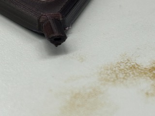
However, this turned out to be a mistake as there was not enough space on the pump holder for the screws to go through it and secure the acrylic seamlessly with it:
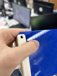
In the picture, you can see that the curve of the white pump holder prevents the acrylic’s side from fully reaching the bottom of the pump holder. This means that the hole drilled into the acrylic cannot line up with those on the pump holder.
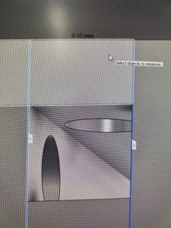
Speaking of drilling holes, I found that it was really difficult to drill holes into the side of a piece of acrylic:
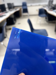
I had to do this step as I originally planned to put screws into the sides of the acrylic as well. However, it was very difficult to drill into the side as the drill bit cannot stay straight. In this picture, the drill bit snapped because it came out of the acrylic at an angle. When it tried to pull it back out, it broke.
When I used a larger bit, I was able to get down around 0.5 inches, but the material eventually cracked open when I tried to pull the bit back out.
So, this idea kind of failed.
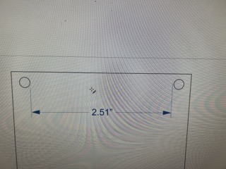
In order to secure the pump holder, I decided to just laser cut out a piece of 1/8 inch plywood. I first figured out the distance between the two holes, and then drew a corresponding sketch in CorelDRAW and conducted the cut:
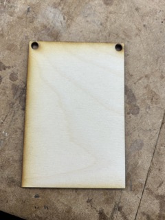
As you can see in the final product of the machine on my group website here, we didn’t use the plywood that I cut out and just let the holders hang on top of the back wall, which worked fine.
The project was spread out over 2 weeks and completed just in the nick of time.