Designing the Machine
First, I designed my machine in the Fusion 360 software:
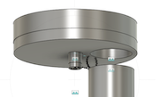
To design my final project, I first had to think about how it would look. I have seen bare bone structures of the motors used to feed the tennis balls such as here:
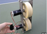
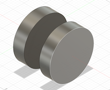
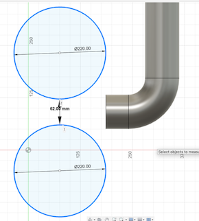
So, I tried to model my design using the image above. For this design, I didn’t sketch out the whole project, rather I just designed most of the machines’ insides, including the ball dispenser and the wheels for firing the balls. First, I searched up the diameter of a tennis ball, which turned out to be around 68 mm. I sketched out two circles on the XZ plane with a diameter of 220mm and extruded them about 7mm in thickness. The two wheels are 7 mm apart from each other (this was a mistake as I will discuss later).
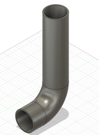
Next, I created a tube with a diameter just a little larger than a tennis ball to pass the tennis ball to the wheels. I first sketched 2 concentric circles about 50 mm from the wheels, and drew lines that guided the tube. Then, I used the sweep tool to complete the tube (selecting the ring as my profile, and the sketch lines as my path).
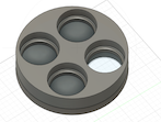
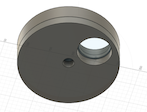
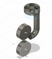
Next, I created 2 plates above the tube that acts as a ball dispenser. The idea is that they will rotate and drop tennis balls one by one into the tube and launch them with the wheels.
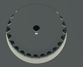
To make the top plate, I used the construct plane tool and selected the top ring of the tube. Then, I offsetted the plane by around 50 mm above the tube. I sketched a circle on it before extruding it to a cylinder. Then, I used the line tool to draw out 4 quadrants of the circle. I drew a small circle in one quadrant. Next, I used the circular pattern feature tool to create an additional 3 circles in each of the other quadrants. Then, I extruded one of the circles all the way through the cylinder as a hole, and extruded the other 3 circles halfway through the cylinder to hold the balls.
The idea is that the top plate will rotate while the bottom plate will stay still. In this way, balls from the top plate will drop down into the bottom plate.
To create the bottom plate, I used the offset plane to create a plane 0.5 mm from the top plate, so that there is room for the top plate to rotate. then, I basically created 4 quadrants and 4 circles, but only extruded one circle all the way through the plate.
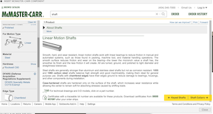
Additionally, I made a small hole in the center of both plates to hold a gear and motor I imported using the McMaster Carr website that is hosted in Fusion.
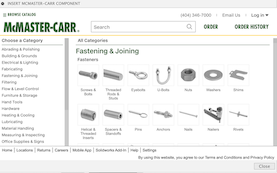
The website contains thousands of parts and it was easy to find a gear and motor. I imported them into my design using a .SAT format.
Using the measure tool, I determined the width of the hole I extruded through both plates, and adjusted the sizes of the gear and motor using the scale tool using percentage ratios and uniform scaling.
Then, I made every body I made in Fusion a component, which enabled me to use to joint feature.
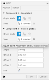
It basically allows you to attach a component to another by selecting specific points on those components. In this way, I was able to attach the center of the gear to the center of the hole on the top plate.
I also attached the center of the motor to the hole in gear.
I created a joint by selecting the top plate and the gear, and set the joint to revolute. When I clicked animate, the top plate began to spin, which was good!
The problem right now is that the hole I extruded in the bottom plate is not aligned over the opening of the tube. Although I used the joint feature, it took several tries to do this, because Fusion kept telling me that there are features in my timeline that could potentially be corrupted.
So, I deleted the failed attempts from my timeline and combined the top, bottom plates, motor, and gear into a rigid group.
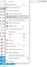
This feature allowed them to move as a group and not separate from each other, as I keep running into the problem where the bottom plate would move and the top wouldn’t.
Then, I selected the joint profiles as the hole in the bottom plate and the tube, and it worked!
Notice that the hole is aligned with the tube.
This is where I discovered that the wheels for launching the ball were built wrong. Instead of them being side by side, they were supposed to be like this:
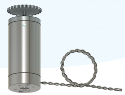
After the extrusion, I made holes in the center of the wheels and found a shaft in McMaster Carr:
I used the joint feature to put the shafts inside the wheels.
This is what I have so far:
In the coming weeks, I will continue to improve upon this design in Fusion.
You can view and download my airplane file here.
You can view and download the latest version of my final project design here.
CAD and Materials Updates
I changed my design a little bit, and incorporated most of the materials that I will be using. I first imported the rail as a CAD model:

I designed the wheels more realistically, and connected it to the shaft:

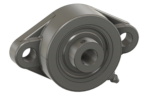
At the end of the shaft, I incorporated a flange:

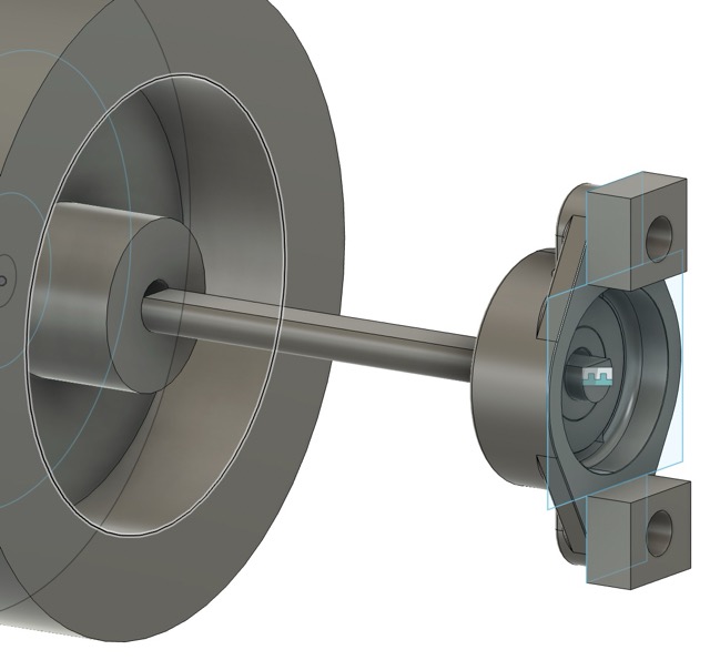
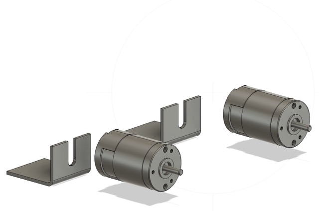
I also imported motors with their corresponding board from McMaster Carr, which I also incorporated into my design as well:
This is my up to date design:

I needed a framework around the wheels of my tennis machine, so I bought aluminum beams, which I will refer to as rails.
I also found a website that sells the tennis machine wheels, they are the cheapest that I could find:

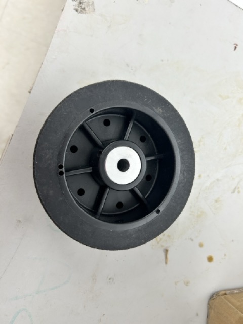
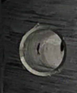
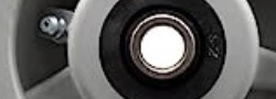
Note that since the wheel must be attached to a 10 mmD-shaft, I needed a motor that has a set screw inside it. The Jbots sports wheel has a set screw (in which I confirmed with the company)
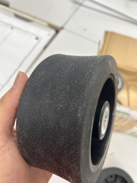
I also considered this wheel that has a rubber coating around it that also has a set screw:

However, I eventually went with the first website as the second wheel was only a wheel that is used on a shopping cart. (I had the idea of combining 2 wheels to fit the width of the tennis ball, but it was too impractical.) Note that the wheels are not molded and casted, unlike my original plan.
Motor Attachment
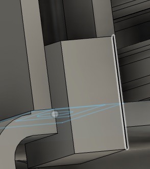
The motor must be screwed into tabs, which go into the grooves of the rails. This is the rail from the side view:

I created a sketch inside the groove:
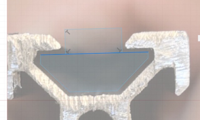
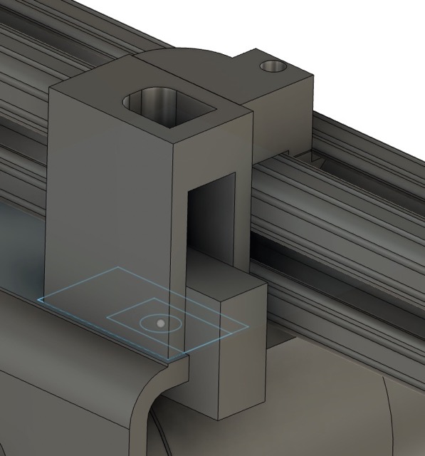
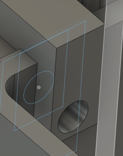
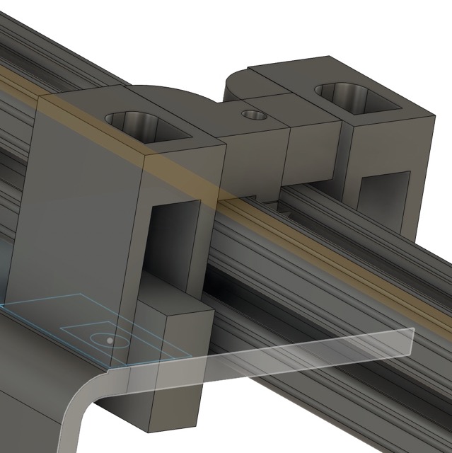
Then, I extruded the groove and extruded a hole inside the tab to simulate an actual tab:
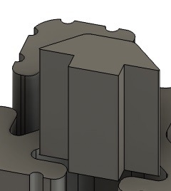
Then, I designed a connector that would bind the motor board to the side rail. Note that I didn’t include any measurements during the process, as it required constant adjustments, which came from measuring the board:
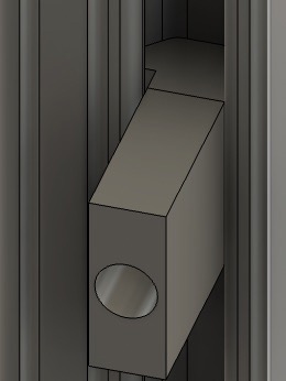
The following pictures show the different orientations of the connector:

This was the completed device in my overall design:
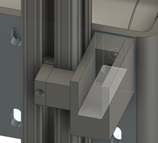
Here are the other views of the device:
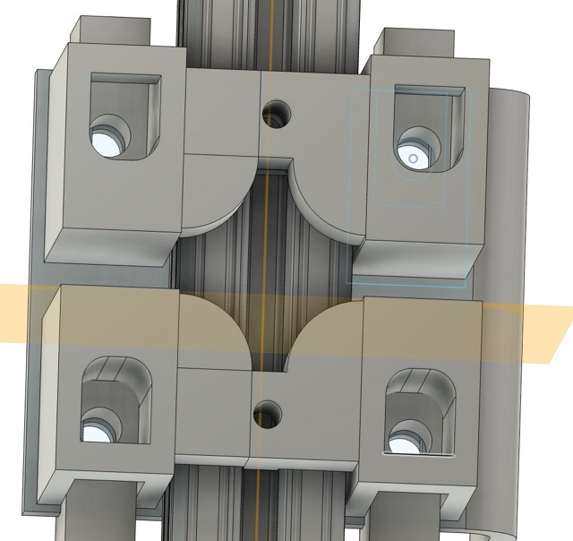
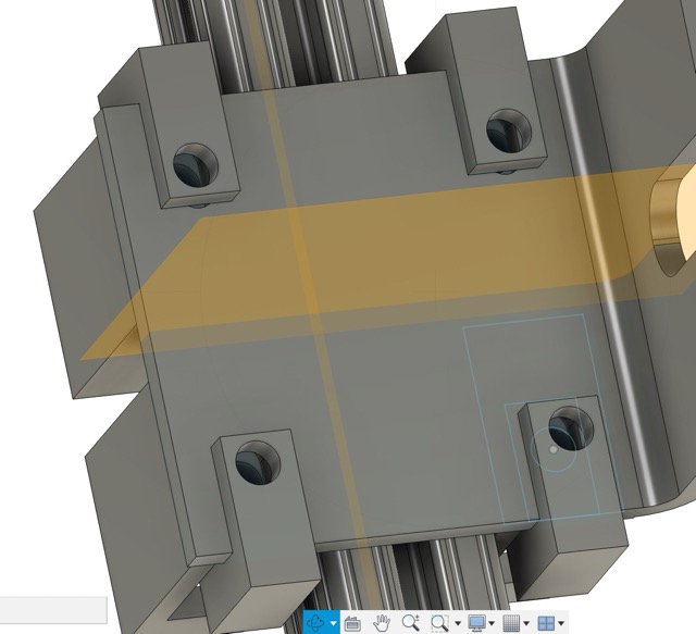
Note how it wraps around the entire rail. Here is front view of the connector with the motor on the motor board:

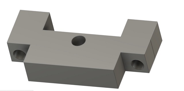
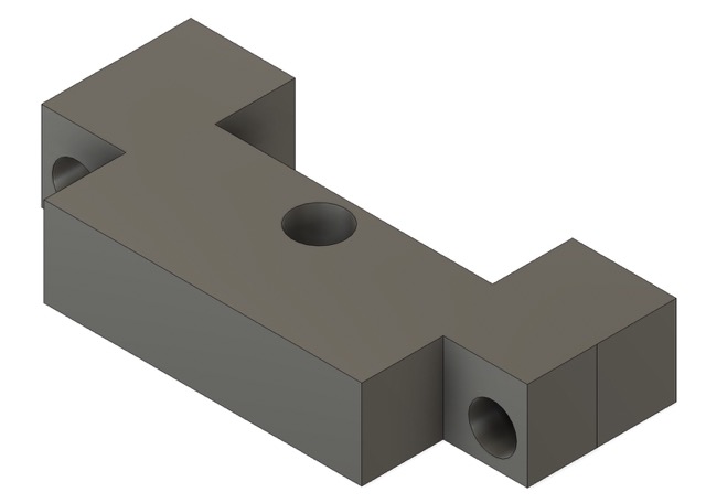
However, in practical terms, this connector wasn’t very effective as I it uses too much material, and it needs 2 tabs in the rail. Also, I worried that the connector might be ripped apart due to the turning of the motor So, I made an updated version of the connector with only one connector. This was the original design of the new connector:
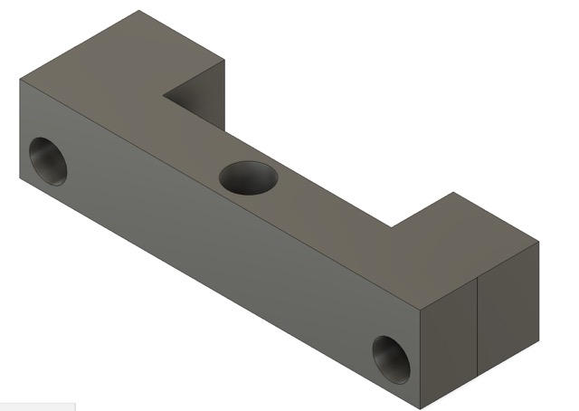
I measured the diameter of certain screws I was going to include in order to determine the size of the corresponding holes on the connector.
But then I realized that I might need more space on the two sides of the connector:
This is the printed design:
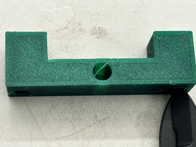
I also measured the printed holes to make sure that the screws fit:

Note that printed holes will be slightly smaller than the ones designed via CAD. I took this into consideration when designing the connector:

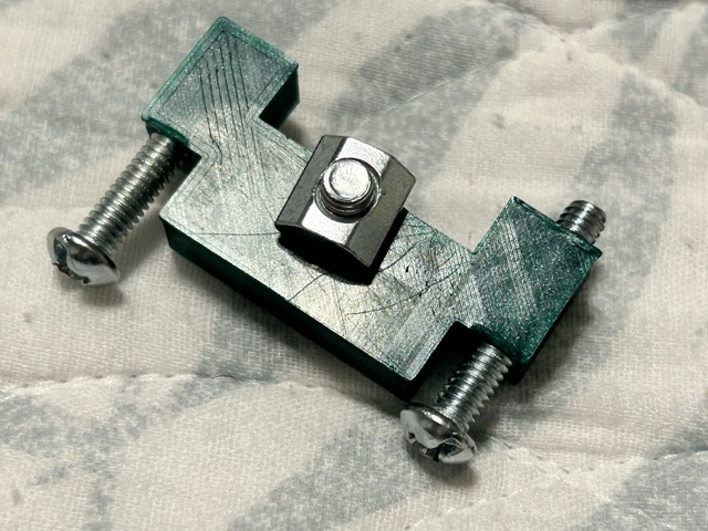
The connector has 2 holes on the sides to connect to the black motor board. Then, one screw in the middle will secure the motor against the rail. I updated my design in the following iterations:

I printed out the final connector design using 20% infill and triangular infill, this is the final product:
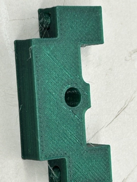 .
.
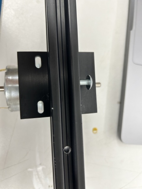
I put the screws as well as the tab connector joint in, and they fit well:

Securing the motor
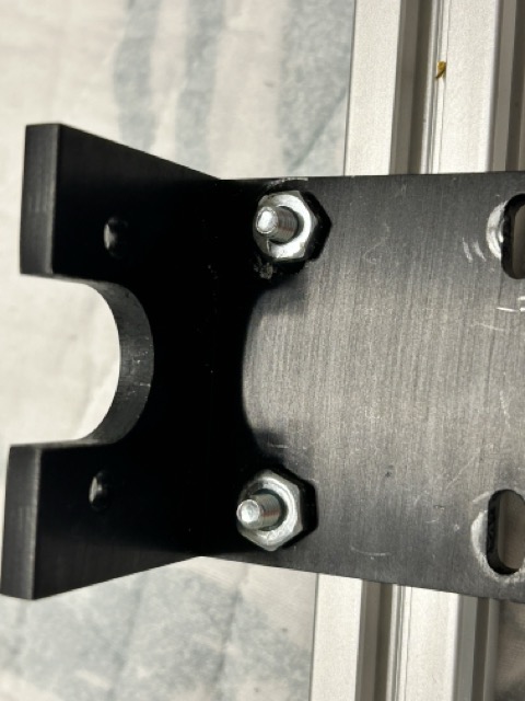
To secure the motor, I first secured the connector the board before attaching the motor. I put the screws and hex nuts towards the side of the motor board so that the screws don’t get in the way of the motor:
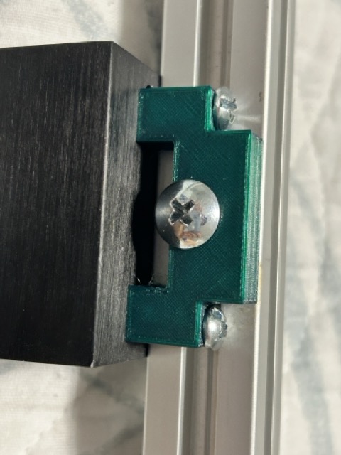
Then, I screwed in the center screw:
Finally, I put in the motor using the screw that it came with:
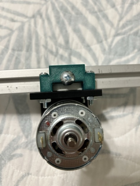

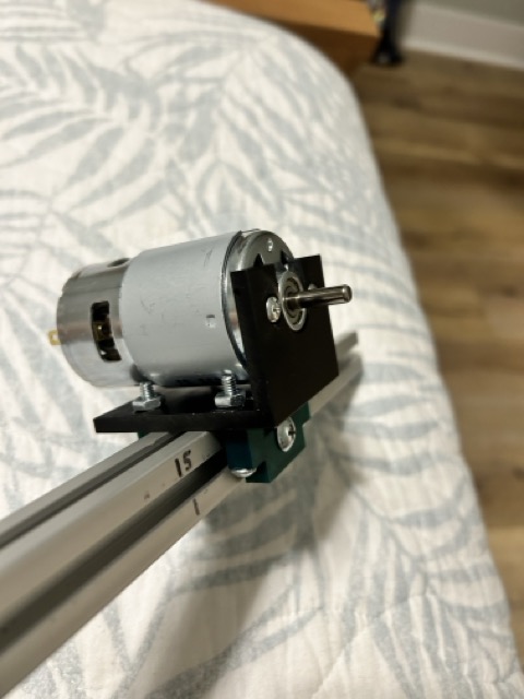
The motor attachment is now complete.
Frame
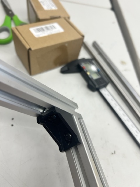
To create the frame that houses the motors, I first made some test cuts by using the bandsaw to cut the aluminum rails:

I also confirmed with Mr. Dubick and Garret that it is safe to cut aluminum with a band saw in the Latin lab.
Then, on the 50 mm beams I bought, I determined that the width should be 32.7 cm, when comparing the length of the 20 mm shaft, couplings, flange, and the motor itself:
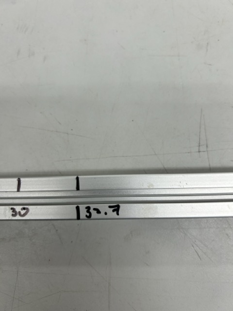
I cut the beams down to the appropriate length, and the rectangular frame lined up pretty well:

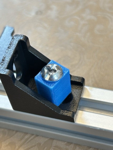
To attach the frames to each other, I bought these accessory parts. At the corners, I used a 90˚ frame with a screw to secure the connection. I also printed out a prism to elongate the screw and strengthen the connection, but it turns out that that wasn’t very helpful:
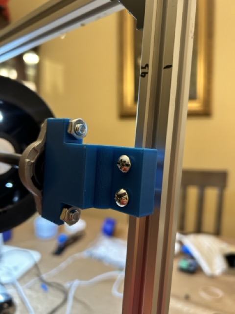
However, when I finished the frame, I felt that the sides can still move and twist around, as the 90˚ accessory attachments left the rails to move in one degree of freedom.
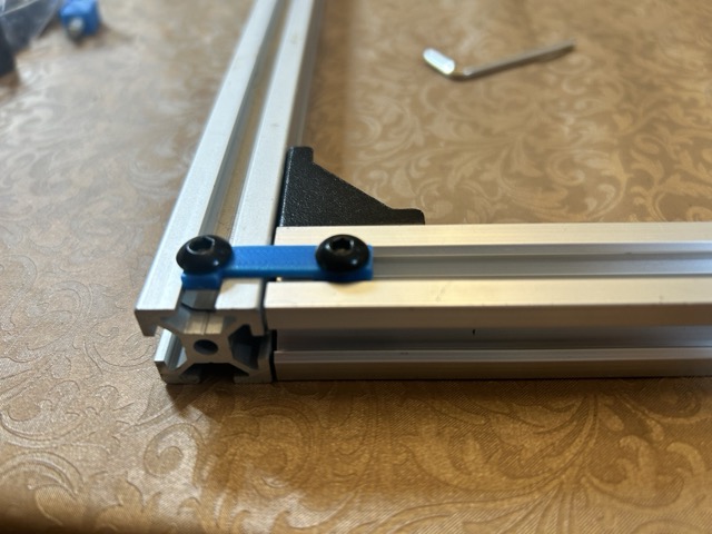
So I designed tabs to hold them in place:
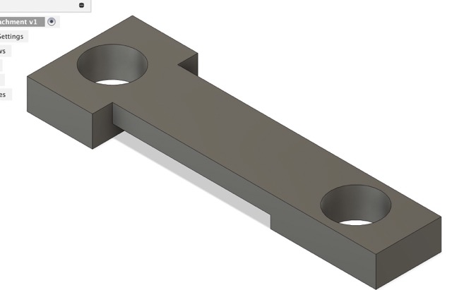
I connected the tabs via screws:
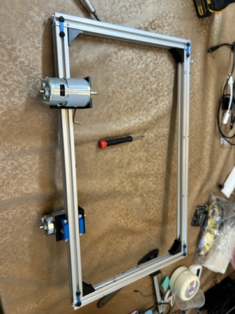
I also connected the other motor on the opposite side:

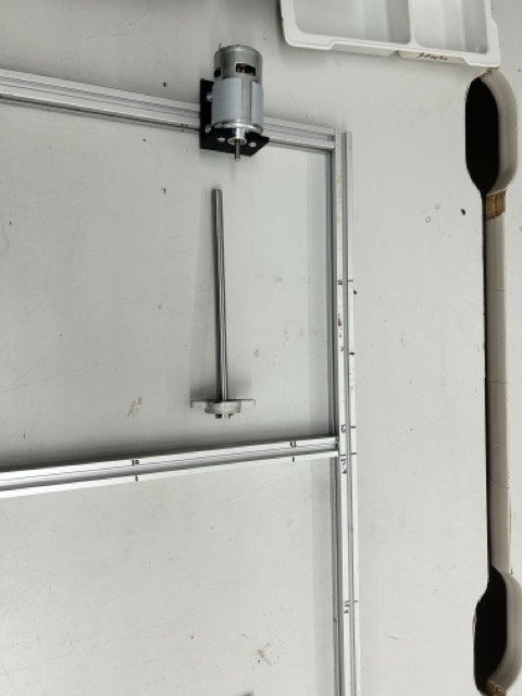
This is the finished frame up to this point:
Coupling, Shaft, and wheels
To attach the shaft to the motor, I went on amazon and bought the following couplings:
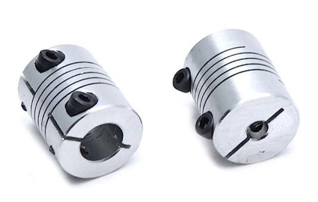
This is the 10mm D-profile rotary shaft that I bought.
By using the set screws in the coupling, I attached the shaft to the motor:
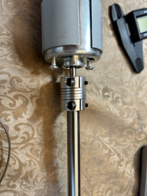
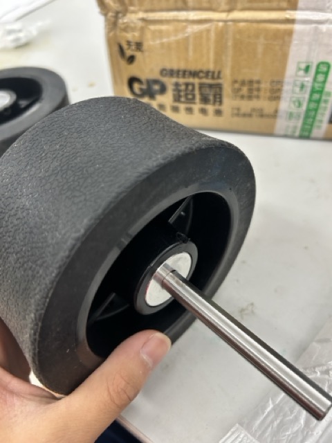
I made sure to screw the set screws into the flat part of the D-profile shaft, as directed by the instructions that came with the coupling. Next, I connected wheel via the set screw built inside:
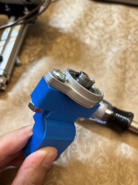
Flange
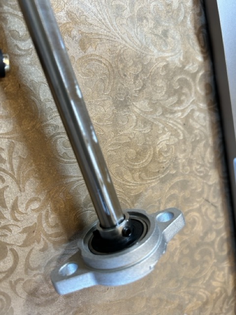
In order to complete the motor and wheel attachment, I bought the following flange that comes lubricated:
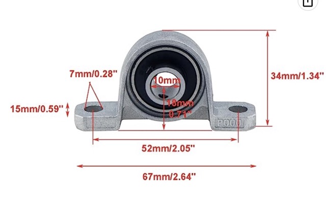
I first tested the flange connection with the shaft:
I designed in Fusion 360 a flange connector:
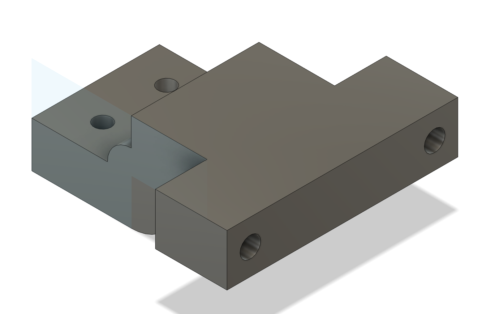
In my base design, I also imported a flange from mcMaster Carr, as seen above
This is the printed flange connector:
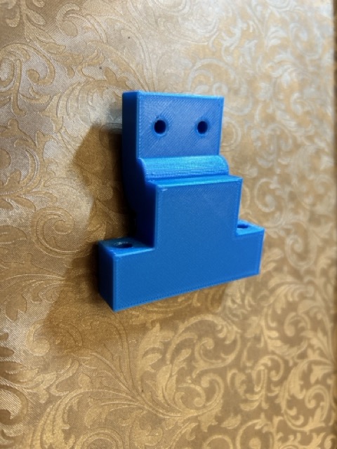
I attached the flange to the connector via two 6 mm diameter nails on either side, and then I connected these parts on to the other rail to finish up the front part of my tennis ball machine:
This is the final construction up to this point:
