Airplane and Final Project
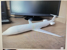
During the weekend, I went to my school to volunteer for an open house event. I helped kids interested in the fab lab 3D print, laser cut, and cut out some stickers via the Silhouette Studios. But I mainly helped a kid to 3D print an airplane.
I found the original model of the jet airliner on Printables, a collection of .stl files that could be printed:
 .
.
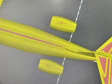
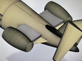
However, when it imported the STL file into PrusaSlicer, a software that produces .gcode files that contains a set of instructions for the 3D printer.
When I sliced the file, I noticed that the engines don’t connect to the plane’s main body:
 .
.
So, I had to import that .stl file into Fusion 360 and fix that missing link. At first, I was confused because the size of the design was massive. In real life, the plane would be as large as a football field! So, when I used the offset plane feature to create another sketch, I had to constantly adjust my input.
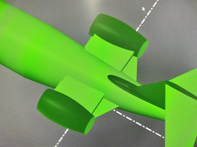
In the end, I found a good number, and created a rectangular prism on the offset plane. Then, I moved that prism over to the horizontal stabilizer of the plane and extruded the prism’s sides so that it joined into its main body. (Side note: the engines were connected to the main body in the original design, but I think it was designed so thin that PrusaSlicer didn’t recognize it.)
Then, I used the rectangular pattern feature to make an exact copy on the other side.
This time, it was successfully sliced in PrusaSlicer.
Final Project Design
To design my final project, I first had to think about how it would look. I have seen bare bone structures of the motors used to feed the tennis balls such as here:
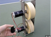
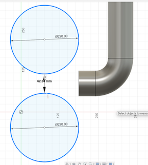
So, I tried to model my design using the image above. For this design, I didn’t sketch out the whole project, rather I just designed most of the machines’ insides, including the ball dispenser and the wheels for firing the balls. First, I searched up the diameter of a tennis ball, which turned out to be around 68 mm. I sketched out two circles on the XZ plane with a diameter of 220mm and extruded them about 7mm in thickness. The two wheels are 7 mm apart from each other (this was a mistake as I will discuss later).
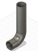
Next, I created a tube with a diameter just a little larger than a tennis ball to pass the tennis ball to the wheels. I first sketched 2 concentric circles about 50 mm from the wheels, and drew lines that guided the tube. Then, I used the sweep tool to complete the tube (selecting the ring as my profile, and the sketch lines as my path).
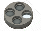
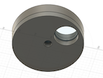
Next, I created 2 plates above the tube that acts as a ball dispenser. The idea is that they will rotate and drop tennis balls one by one into the tube and launch them with the wheels.
To make the top plate, I used the construct plane tool and selected the top ring of the tube. Then, I offsetted the plane by around 50 mm above the tube. I sketched a circle on it before extruding it to a cylinder. Then, I used the line tool to draw out 4 quadrants of the circle. I drew a small circle in one quadrant. Next, I used the circular pattern feature tool to create an additional 3 circles in each of the other quadrants. Then, I extruded one of the circles all the way through the cylinder as a hole, and extruded the other 3 circles halfway through the cylinder to hold the balls.
The idea is that the top plate will rotate while the bottom plate will stay still. In this way, balls from the top plate will drop down into the bottom plate.
To create the bottom plate, I used the offset plane to create a plane 0.5 mm from the top plate, so that there is room for the top plate to rotate. then, I basically created 4 quadrants and 4 circles, but only extruded one circle all the way through the plate.
Additionally, I made a small hole in the center of both plates to hold a gear and motor I imported using the McMaster Carr website that is hosted in Fusion.
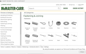
The website contains thousands of parts and it was easy to find a gear and motor. I imported them into my design using a .SAT format.
Using the measure tool, I determined the width of the hole I extruded through both plates, and adjusted the sizes of the gear and motor using the scale tool using percentage ratios and uniform scaling.
Then, I made every body I made in Fusion a component, which enabled me to use to joint feature.
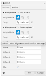
It basically allows you to attach a component to another by selecting specific points on those components. In this way, I was able to attach the center of the gear to the center of the hole on the top plate.
I also attached the center of the motor to the hole in gear.
I created a joint by selecting the top plate and the gear, and set the joint to revolute. When I clicked animate, the top plate began to spin, which was good!
The problem right now is that the hole I extruded in the bottom plate is not aligned over the opening of the tube. Although I used the joint feature, it took several tries to do this, because Fusion kept telling me that there are features in my timeline that could potentially be corrupted.
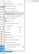
So, I deleted the failed attempts from my timeline and combined the top, bottom plates, motor, and gear into a rigid group.
This feature allowed them to move as a group and not separate from each other, as I keep running into the problem where the bottom plate would move and the top wouldn’t.
Then, I selected the joint profiles as the hole in the bottom plate and the tube, and it worked!
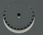
Notice that the hole is aligned with the tube.
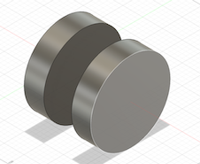
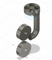
This is where I discovered that the wheels for launching the ball were built wrong. Instead of them being side by side, they were supposed to be like this:
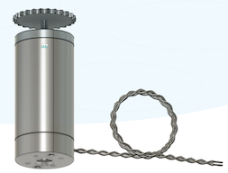
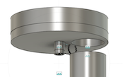
After the extrusion, I made holes in the center of the wheels and found a shaft in McMaster Carr:
I used the joint feature to put the shafts inside the wheels.
This is what I have so far:
In the coming weeks, I will continue to improve upon this design in Fusion.
Compressing trouble
Later, as I was trying to compress the .f3d files into my repository, I ran into some trouble. Even though the file was zipped, the file size didn’t go down or change at all. When I tried to right click and make an alias (which references the original file), it still didn’t work because the original file has to be at the same location as the alias.
I deleted that file and then tried to run git push but it didn’t work. There seemed to be a very large file some where that is taking up all the space. Then, I headed into terminal and ran:
find . -size +15M
to find all the files tht are larger than 15 megabytes or larger in my repository.
I found the file, but for some reason, I cannot open it. So I used the rm feature to delete the file through terminal. However, the moment I did that, git push suddenly cannot work anymore because it relied on that file, so I tried to recover that .git file, but it became a total mess. I don’t fully understand how to work with the command line, branches, and git-related commands. So, instead I just cloned by existing repository again and deleted the old one. Then, I put the old files into the new local directory. It worked.
To compress the airplane file, I scaled the model way down using the scale feature, and I scaled it down by 99%. Unluckily, Fusion crashed, and I had to force quit and restart it again. However, when I imported the .f3d file into my repository again, it was still 18 million bytes. I simply cannot shrink the size of the file.
I decided to consult former student Nick Niles for help. Instead of putting the downloaded files inside my repository and expanding it to a huge size, I figured out a way to create a shareable link in Fusion 360 and decided to put that in here:
You can view and download my airplane file here.
You can view and download my latest version of my final project design here.