ATtiny 412
An ATtiny412 is a microcontroller that could be programmed by an Arduino. It uses very low power, but could produce a sizeable output. Even though it has much less functionality than an Arduino, it is enough for most electronics projects and applications.
Before Fab Academy started, I programmed an ATtiny412. A crucial thing to note is that the pins on the chip are confusing to read, but I will try my best to explain them down below.
Pin outs
When an Arduino programs an ATtiny412, the Arduino itself is a programmer.
Pin Description:
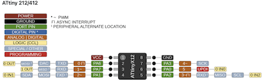
The first thing to note is there is a difference between the software and hardware pins.
On the Arduino Uno, the software pin is connected to pin 4 on the ATtiny 412, thi is not to be confused with the hardware pin on the Arduino. So, to program it in the Arduino software, you must put pin 2.
UPDI:
The UPDI supports ATtiny412 programming. It allows the Arduino to directly program the chip.
The UPDI pin is connected to pin 6 on the chip, but even though the software pin on the Arduino is 5, you have to connect it to pin 6 in order for it to work.
Blinking LED
Basic Workflow
Here is the basic workflow for creating a simple blinking LED (aka Hello World) program using the ATtiny 412.
- Open 2018 version Arduino INC.
- Go to file, examples, jtag2updi, make sure that the selected board is Arduino Uno R3.
- Open jtag2updi code, and upload to Arduino Uno, this makes the arduino a programmer.
- Go to file, examples, basic, blink.Open blink code.
- Select board as ATtiny412 through tools, board, megaTinyCore.
- Select programmer as jtag2updi.
- Select chip as Attiny412, and Port as COM17.
- Make sure to connect pin6 on the Arduino to UPDI pin on the ATtiny412.
Code for Blinking LED
/*
    Blink

Turns an LED on for one second, then off for one second, repeatedly.

 Most Arduinos have an on-board LED you can control. On the UNO, MEGA and ZERO are attached to digital pin 13, on MKR1000 on pin 6.
 LED_BUILTIN is set to the correct LED pin independent of which board is used.

 By Scott Fizgerald, 8 May 2014.
 modified 2 Sep 2016 by Arturo Guadalupi
 modified 8 Sep 2016 by Colby Newman

 */

 // the setup function runs once when you press reset or power the board

 void setup(){
    // initialize digital pin LED_BUILTIN as an output.
    pinMode(2, OUTPUT);
 }

 // the loop function runs over and over again forever

 void loop(){
    digitalWrite(2, HIGH);
    delay (1000);
    digitalWrite(2, LOW);
    delay (1000);
 }
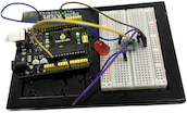
Wiring
This is the wiring for the program:
More information
To read more about milling out boards, click here.
To read more about setting up an ATtiny412 board, click here, the website is made by Teddy Warner.