Programming
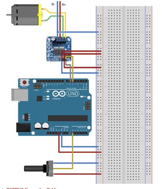
I used an H-bridge and a potentiometer to program a Tetrix motor, which could adjust its speed. These motors are used to control the speed of the tennis ball and its spin. (STILL NEED TO EDIT ~ from week 9).
Gearbox Testing
I decided that the spin rate of my motors were too fast, and so I decided to build a simple lego gearbox to adjust for the correct torque.
It can either scale up the torque or scale it down.
I decided to build gear ratios with the lego box and 3D print attachments to the gears that fit with the Tetrix motor.
I went to this youtube video that was really helpful in understanding a gearbox.
Following the visual in the video:
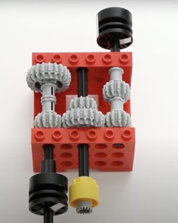
I made my own lego gearbox. Later, I plan to buy metallic motors that have more defined edges and are stronger than the lego pieces.
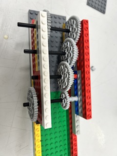
Notice that the gearbox contains gears with smaller teeth interlocking their teeth with larger gears. Although this decreases the torque, it increases the speed of the gear. This is an inverse relationship.
Through my calculations, the first gear rotates about ⅕ for every time I spin the last gear. This means that when the Tetrix motor spins at 100 rpm, the last one will spin around 400-500 rpm. However, this also means that the last gear will have ¼-⅕ less torque.
Time to design the connector for the motor. This will have the joint for the tetrix motor on one end and a connector for the lego axle on the other.
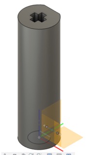
When it was printed out however:
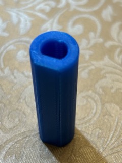
I noticed that it was too loose when fitted with the tetrix motor’s shaft. As a result, I have to reduce the offset from the tetrix motor’s dimensions by 0.2mm on both sides.
Here is the current video for the tetrix motor turning the gears:
(A very quick note that this video was originally not working, and I updated it according to the format as described in week 18. In Terminal, I updated the ffmpeg tool by running brew install ffmpeg).
There was one problem, however. I noticed that the torque was way too low. With the slightest tap on the end motor, the tetrix motor would buckle under the torque pressure and it would stop spinning completely and start to turn itself.
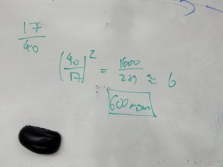
According to its data sheet, the tetrix motor has 700 oz -in of torque, which translates to around 43.75 pounds. The smaller gears in the gear box have 17 teeth, while the larger one has 40. Since there are 5 levels of gears (I added another one), there are 4 reductions in torque, resulting in:

pound inch of torque.
This is clearly far from enough. My calculations could be off given that I probably used less than a pound of force with my finger and stopped the motor.
Choosing a motor
This was kind of a difficult process as there were not a lot of small DC motors that had high torque.
I have 2 options:
The first is to buy an extremely high torque tetrix motor and adapt it into the lego gear box to make the model. The second is to straight up by a high torque, high speed regular 12 volt DC motor that eliminates the use of the gear box.
After asking ChatGPT, it tells me the options for each one:
| High torque tetrix motor alternatives | High torque + high speed DC motor |
|---|---|
| AndyMark NeveRest Motors Torque = 8.75 oz in | Faulhaber DC motor Torque = 2.688 oz in |
| REV Robotics HD Hex Motor Torque ≈ 600 oz in |
I realized that the torques of these motors are still too small. The Falhaber motor has a top speed of 11000 rpm. I only needed the ball machine to spin at around 1000 rpm. So its torque would be increased to around 30 oz in, or less than 2 pounds, definitely not enough.
After a bit of searching, I found this motor from an official tennis ball machine replacement store. Although there is no official product description, I think it is worth a shot. After checking in with my parents, my dad (who has a degree in Industrial Automation) told me that since there was no official product description, it is not worth buying it. So I continued to look for a suitable motor on McMaster Carr.
After contacting the company via phone number, I was able to find 2 OK motors: the square face motor at 4200 rpm and 40 in-oz, and the brush motor at 3000 rpm and 21 in-oz.
When I discussed each option with my dad, we found that the torque is still too small.
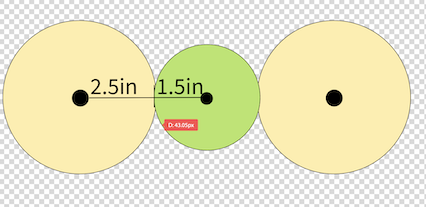
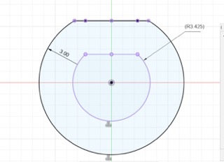
The above drawing shows my current plan. The wheels will be 5 inches in diameter, molded and made out of resin, with a coat of rubber around it. The tennis ball has a weight of 3 ounces, and a diameter of 3 inches approximately. So, the distance, R, from the center of the gear to the center of the tennis ball is around 4 inches, so in reality I would need to divided the torque of the motor by 4 in order to get the actual torque begin applied to the tennis ball.
After reviewing this video again, I realized that the motors they used are only 12 volt ones, and nothing more. So, I set out to find a motor with extreme speed, and I did find one. It is a RS550 motor. This data sheet shows that it has a torque of 551 g cm, which roughly translates to 7 in oz. However, its spin rate is 40000 RPM, meaning that if I made a gear box and changed that to 1000 RPM, I would get a resulting torque of 40 * 7 = 280 in oz of torque, which is around 17.5 lb in. (After a division of 4, resulting in a 4.25 pounds of force on the tennis ball).
This is far more than what I anticipated than the tetrix motor, leading me to believe that this design might actually work, it just requires the addition of a gear box, which I can either make or buy one.
However, after further consideration, I decided to abandon the gear box idea as it contains a lot of moving parts. The amount of parts that it has increases the chance of the motors breaking down. Also, it would be difficult to remove or add gears to the gear box in order to adjust for the correct torque. Overall, I thought it was cumbersome and tedious to use a gear box.
Then, I found this video documenting a working tennis ball machine. The motor they used was a 775 motor spinning at 7,000 RPM at 24 volts, and it seemed that it had enough power to rotate a plastic wheel at high speed and can shoot the ball for 60 to 70 feet. I found the motor on amazon:
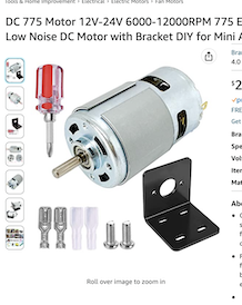
I tested the motor using a power supply to measure the current of the motor:
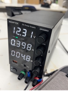
The maximum current spike was around 4 amps when I put my finger against the motor, and when it rapidly accelerates. Although it is able to maintain a stable current of 0.4 amps when running regularly. The fact that the spike is far above the H-bridge’s upper limit of 2 amps means I needed a motor shield that has a limit of 20 amps or more.
The torque of the new motor seems fine, as stopping it with the finger was impossible.
Programming Phase 2
As seen in the previous 2.5 Design phase 2 section of this documentation, I am coming back from a long break on my project. This section will detail the rest of my work so far (as of 4/8/2024) on programming the motors.
Motor Details
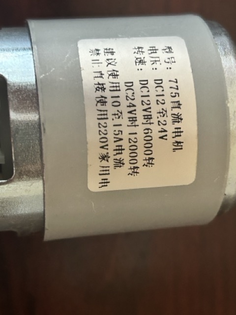
The motor I am using, as described above, is a DC 775 motor, which has the following self-proclaimed voltage and current:
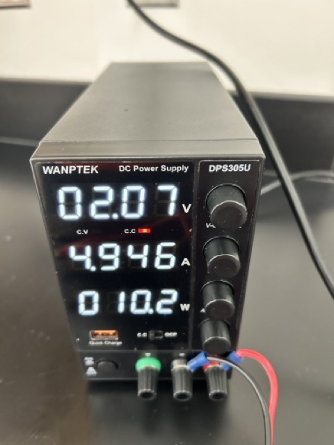
Next, I connected the DC motor up to a power supply, and saw the following values for its working voltage and current.

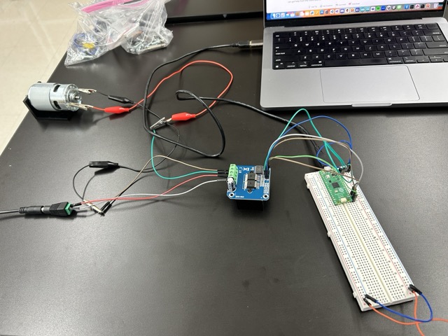
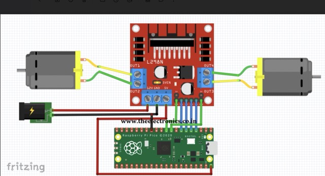
Then, I used this 43 amp motor shield to control the motor by putting everything in a circuit.

However, I was worried that this would be dangerous as I am working with a lot of voltage that is not contained.
Small Motor Control
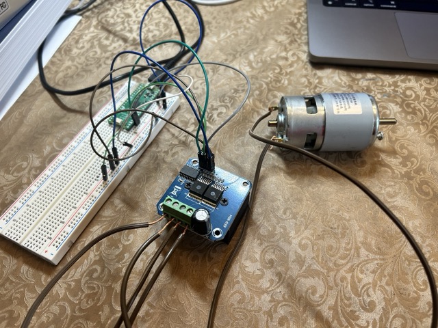
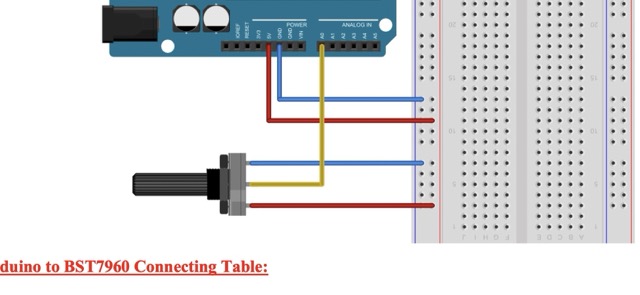
So I decided to wire a small 5 volt DC motor first to the motor shield, using the same schematic as week 9.
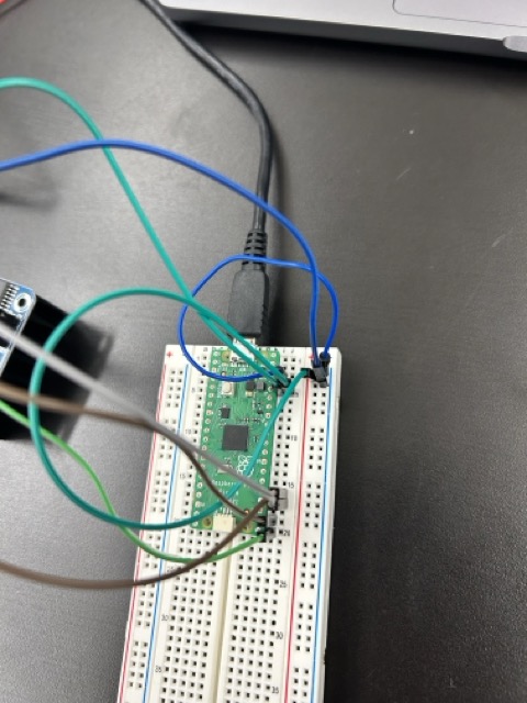
At first, the motor didn’t spin because when I tested the voltage, it is always decreasing due to some reason. I was using a 12 volt power adaptor that is connected to the power pin on the motor shield. When I first measured the voltage difference between the power and ground pins, I got a voltage of 12.28v.

However, the voltage difference quickly dropped to 1.8v.
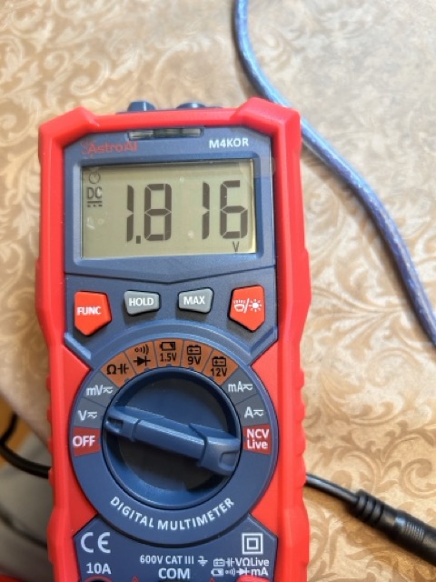
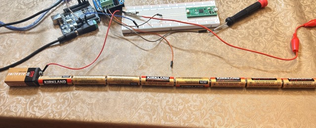
I had no idea why. I even tested it with many batteries connected together, but the voltage across all those batteries was still dropping continuously. I wondered if there was a problem with my multimeter, which was mostly likely the problem.
Then, I switched out the batteries for my multimeter and tested it again, to no avail.
Through out this whole process, even though the motor was plugged in, it was not spinning at all, and this was just the small 5 volt DC motor.
Working
So, I decided to take a step back and use the Arduino Uno instead of the Raspberry Pi to power the motor. I wired it and it worked!
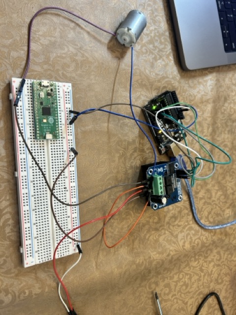
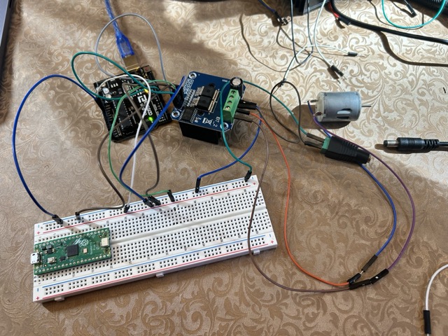
Then, I wired the motor again using the Pi, and this time I tried another motor shield (43 A). This time, the 5v motor spun according to the example code shown below:
int enA = enA;
int in1 = pin1;
int in2 = pin2;

void setup() {
  // put your setup code here, to run once:

pinMode(enA, OUTPUT);
pinMode(in1, OUTPUT);
pinMode(in2, OUTPUT);
Serial.begin(9600);
}


void demoOne(){
  // This will run the motor in both directions at a fixed speed.

  digitalWrite(in1, HIGH);
  digitalWrite(in2, LOW); // initiation, and spinning it clockwise
  analogWrite(enA, 200);

  delay(2000);

 digitalWrite(in1, LOW);
  digitalWrite(in2, HIGH); // turn it the other way.
  delay(2000);
  digitalWrite(in1, LOW);
  digitalWrite(in2, LOW);
}

void demoTwo(){
  digitalWrite(in1, HIGH);
  digitalWrite(in2, LOW);

  for (int i = 0; i < 256; i++){
    analogWrite(enA, i);
    delay(20);
  }

  for (int i = 255; i>= 0; --i){
    analogWrite(enA, i);
    delay(20);
  }
  digitalWrite(in1, LOW);
  digitalWrite(in2, LOW);
}


void loop() {
  // put your main code here, to run repeatedly:
demoOne();
delay(1000);
demoTwo();
delay(1000);
}
Obviously, the pin numbers are substitutable.
Large motor Control
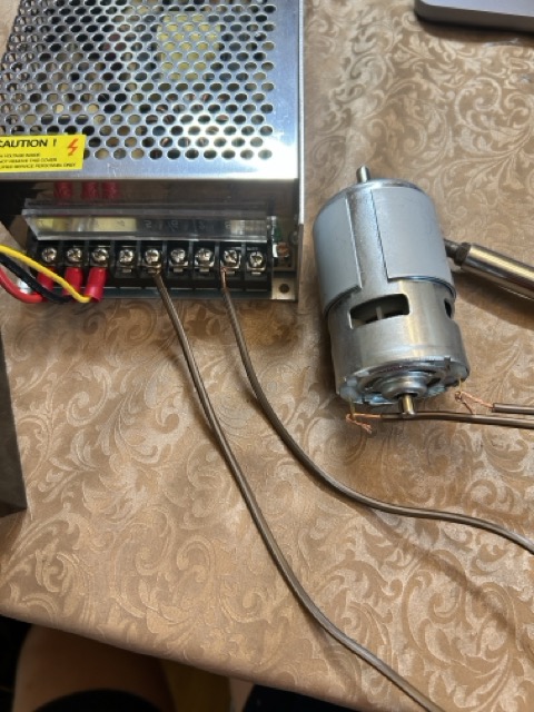
With the small motor working, I wired the large motor up to a giant power supply that provides a maximum of 25 volts and 20 amps. This power supply is the one I used.
This picture shows the wiring for the large motor. Notice that I am using heavy-duty copper wires that could withstand to a hundred amps instead of the unreliable jumper wires.
I didn’t fully solder the jumper wires copper core directly to the motor to allow room for error.
This time, I was able to get the motor to spin slowly, but it looks like that there is still not enough current for the motor. It now moves, but fairly slow.
Working
So, I increased amount of current applied to the motor, and tested it. The motor now works using the above testing code! It worked with the heavy duty motor shield that is directly controlled by the Raspberry Pi. Here is the working video:
Application
First, I connected the motor to the D-profile shaft via a coupling to see if it can be spun. The end of the shaft was connected to the flange.
Then, I installed both motors on to my front frame of the tennis ball machine, and spun the motor. The motor is attached to the wheel via a set screw, and it took some time to accelerate. Once it got up to speed, the wheel spun pretty powerfully, and the rubber felt strong enough to shoot a tennis ball. I think I will implement more screws and 3D printed parts in order to make sure that the centrifugal forces would not tear the frame apart.
Phase 3: Re-working
As of 4/8/24, I have not touched my project in couple of months, and my first step in programming is to make sure that I can get the 775 motor to work properly, then I will implement the potentiometer.
Reworking the Motors
I basically used the same process as in the previous part of this page to get the motors to work. First, I soldered wires onto the small motor and tried to get it to work. It spun when both ends of the motor touched the + and - of the power supply. The diagram I revisited was given by Merritt Backerman here:
Based on this wiring, I wired the small motor to my HW-039 motor driver, although I used GPIO pins for the R_EN and L_EN pins. This did not work when I made both of these pins outputs and tried to run the program. So I went back to the HW-039 data sheet and found that both of the pins were connected to the common VCC:
So, I wired it as shown and the small motor turned on.

I moved on to the big motor, and wired it the same way as above. It worked as well.
Here is the working code for both motors:
const int Red_RPWM = 0;
const int Red_LPWM = 1;
const int White_RPWM = 2;
const int White_LPWM = 3;

void setup() {
  // put your setup code here, to run once:


 // pinMode(R_EN, OUTPUT);
 // pinMode(L_EN, OUTPUT);
  pinMode(White_RPWM, OUTPUT);
  pinMode(White_LPWM, OUTPUT);
  pinMode(Red_RPWM, OUTPUT);
  pinMode(Red_LPWM, OUTPUT);

}


void loop() {
  // put your main code here, to run repeatedly:


  // digitalWrite(R_EN, HIGH);
  // digitalWrite(L_EN, LOW);
   analogWrite(White_RPWM, 150);
   analogWrite(White_LPWM, 0);
   analogWrite(Red_RPWM, 150);
   analogWrite(Red_LPWM, 0);
  /* for (int i=0; i<300; i++){
  analogWrite(RPWM, i);
  delay(20);
}

for (int j=299; j>-1; --j){
  analogWrite(RPWM, j);
  delay(20);*/
}
Here is the motors working:
Potentiometer
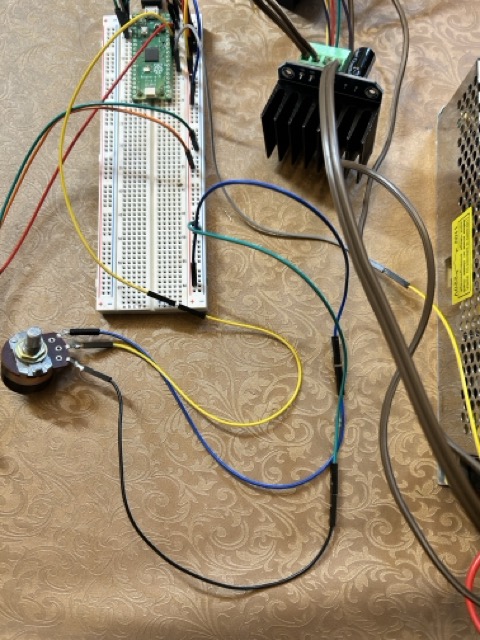
I found this diagram in the HW-039 data sheet to wire the potentiometer:
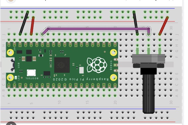
At first, I thought that the data pin would work with any GPIO pin on the Pico, but according to this website and pinout diagram, the data pin must be wired to one of the 3 analog input pins on the pico, which were GPIO 26, 27, and 28. I did so, and got the code from the HW-039 datasheet. This diagram also helped:
The potentiometers worked as intended:
This is the code working with the pot resistor that controls the red motor(motor with red flange connector):
The numbers that you see here are thresholds for the motor to turn in one direction or the other. Basically, the pico reads the value of the potentiometer, and spins the motor based on that value. If it is above the threshold, it spins clockwise, and anti-clockwise if it is below the threshold.
const int Red_RPWM = 0;
const int Red_LPWM = 1;
const int White_RPWM = 2;
const int White_LPWM = 3;
const int red_pot = 28;
const int led = 10;

void setup() {
  // put your setup code here, to run once:

 // pinMode(R_EN, OUTPUT);
 // pinMode(L_EN, OUTPUT);
  pinMode(White_RPWM, OUTPUT);
  pinMode(White_LPWM, OUTPUT);
  pinMode(Red_RPWM, OUTPUT);
  pinMode(Red_LPWM, OUTPUT);
pinMode(led, OUTPUT);


}

void loop() {
  // put your main code here, to run repeatedly:

  // digitalWrite(R_EN, HIGH);
  // digitalWrite(L_EN, LOW);

  /* for (int i=0; i<300; i++){
  analogWrite(RPWM, i);
  delay(20);
}

for (int j=299; j>-1; --j){
  analogWrite(RPWM, j);
  delay(20);*/


int sensorValue = analogRead(red_pot);
// sensor value is in the range 0 to 1023
// the lower half of it we use for reverse rotation; the upper half for forward
// rotation
if (sensorValue < 400)
{
// reverse rotation
 int reversePWM = -(sensorValue - 399) / 2;
analogWrite(Red_LPWM, reversePWM);
analogWrite(Red_RPWM, 0);

// digitalWrite(led, LOW);
}
else
{
// forward rotation
 int forwardPWM = (sensorValue - 400) / 2;
analogWrite(Red_RPWM, forwardPWM);
analogWrite(Red_LPWM, 0);
// digitalWrite(led, HIGH);
}
}
Then, I modified the code to fit the other pot resistor as well:
const int Red_RPWM = 0;
const int Red_LPWM = 1;
const int White_RPWM = 2;
const int White_LPWM = 3;
const int red_pot = 28;
const int white_pot = 27;


void setup() {
  // put your setup code here, to run once:


 // pinMode(R_EN, OUTPUT);
 // pinMode(L_EN, OUTPUT);
  pinMode(White_RPWM, OUTPUT);
  pinMode(White_LPWM, OUTPUT);
  pinMode(Red_RPWM, OUTPUT);
  pinMode(Red_LPWM, OUTPUT);

}

void loop() {
  // put your main code here, to run repeatedly:


  // digitalWrite(R_EN, HIGH);
  // digitalWrite(L_EN, LOW);


  /* for (int i=0; i<300; i++){
  analogWrite(RPWM, i);
  delay(20);
}

for (int j=299; j>-1; --j){
  analogWrite(RPWM, j);
  delay(20);*/


int redValue = analogRead(red_pot);
int whiteValue = analogRead(white_pot);
// sensor value is in the range 0 to 1023
// the lower half of it we use for reverse rotation; the upper half for forward
// rotation
if (redValue < 350)
{
// reverse rotation
 int reversePWM = -(redValue - 349) / 2;
analogWrite(Red_LPWM, reversePWM);
analogWrite(Red_RPWM, 0);

// digitalWrite(led, LOW);
}

if (whiteValue < 350){

  int reversePWM = -(whiteValue - 349) / 2;
analogWrite(White_LPWM, reversePWM);
analogWrite(White_RPWM, 0);

}

if (whiteValue > 350){
  int forwardPWM = (whiteValue - 350) / 2;
analogWrite(White_RPWM, forwardPWM);
analogWrite(White_LPWM, 0);
}
else if (redValue > 350)
{
// forward rotation
 int forwardPWM = (redValue - 350) / 2;
analogWrite(Red_RPWM, forwardPWM);
analogWrite(Red_LPWM, 0);
// digitalWrite(led, HIGH);
}
}
However, there was a slight problem. Because of the way the if statements are written, it is only going to one if statement at a time. For instance, if whiteValue > 350, but redValue < 350, the program will still turn the red motor in reverse but not change the direction of the white motor.
So, one option is to write include the && operator and include 4 different if statements. But that would be redundant. I asked ChatGPT to come up with a more efficient code and modified it. I came up with this:
const int Red_RPWM = 0;
const int Red_LPWM = 1;
const int White_RPWM = 2;
const int White_LPWM = 3;
const int red_pot = 28;
const int white_pot = 27;

const int sensor_threshold_red = 450;
const int sensor_threshold_white = 420;


void setup() {
  // put your setup code here, to run once:
 // pinMode(R_EN, OUTPUT);
 // pinMode(L_EN, OUTPUT);
  pinMode(White_RPWM, OUTPUT);
  pinMode(White_LPWM, OUTPUT);
  pinMode(Red_RPWM, OUTPUT);
  pinMode(Red_LPWM, OUTPUT);

}

void loop() {

  // put your main code here, to run repeatedly:

  /* for (int i=0; i<300; i++){
  analogWrite(RPWM, i);
  delay(20);
}

for (int j=299; j>-1; --j){
  analogWrite(RPWM, j);
  delay(20);*/

int redValue = analogRead(red_pot);
int whiteValue = analogRead(white_pot);
// sensor value is in the range 0 to 1023
// the lower half of it we use for reverse rotation; the upper half for forward
// rotation

controlMotor(Red_RPWM, Red_LPWM, redValue, sensor_threshold_red);
controlMotor(White_RPWM, White_LPWM, whiteValue, sensor_threshold_white);

}

void controlMotor(int pwmPinForward, int pwmPinReverse, int sensorValue, int sensorThreshold){
  if (sensorValue < sensorThreshold){
    int reversePWM = -(sensorValue - sensorThreshold)/2;
    analogWrite(pwmPinReverse, reversePWM);
    analogWrite(pwmPinForward, 0);
  }
  else if (sensorValue > sensorThreshold){
    int forwardPWM = (sensorValue - sensorThreshold)/2;
    analogWrite(pwmPinForward, forwardPWM);
    analogWrite(pwmPinReverse, 0);
  }
  else {
    analogWrite(pwmPinForward, 0);
    analogWrite(pwmPinReverse, 0);
  }
}
The function void controlMotor is going to control both motors simultaneously.
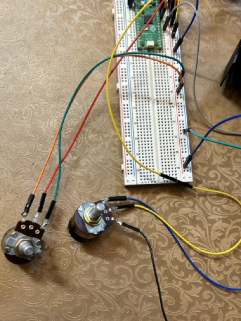
I also found that the potentiometer controlling the white motor adjusted too fast by turning it and measuring its resistance with an olm-meter, and so I switched it for another one.
Here are the motors working:
OLED Display
Next, I had to get the OLED display to work with an Arduino, and then my Pico.
Here is the wiring from this tutorial:
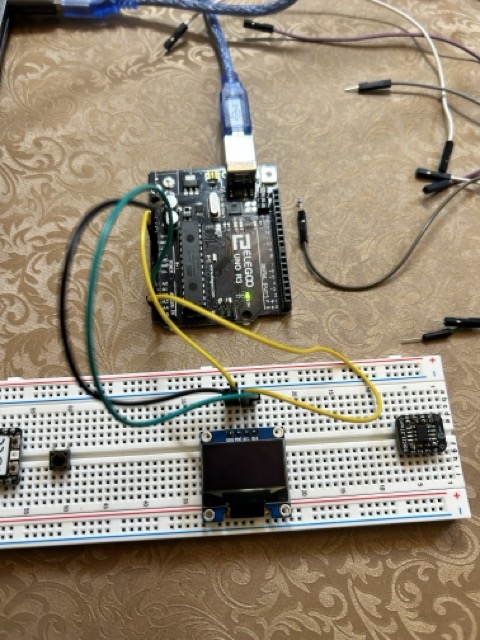
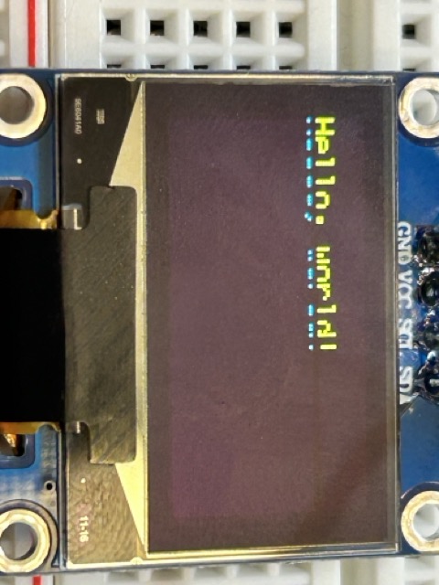
After uploading the following code, I was able to print “Hello world” on the display:
/*********
  Rui Santos
  Complete project details at https://randomnerdtutorials.com
*********/

#include <Wire.h>
#include <Adafruit_GFX.h>
#include <Adafruit_SSD1306.h>
#include <Fonts/FreeSerif9pt7b.h>

#define SCREEN_WIDTH 128 // OLED display width, in pixels
#define SCREEN_HEIGHT 64 // OLED display height, in pixels

// Declaration for an SSD1306 display connected to I2C (SDA, SCL pins)
Adafruit_SSD1306 display(SCREEN_WIDTH, SCREEN_HEIGHT, &Wire, -1);

void setup() {
  Serial.begin(115200);

  if(!display.begin(SSD1306_SWITCHCAPVCC, 0x3C)) {
    Serial.println("SSD1306 allocation failed");
    for(;;);
  }
  delay(2000);

  display.setFont(&FreeSerif9pt7b);
  display.clearDisplay();
  display.setTextSize(1);
  display.setTextColor(WHITE);
  display.setCursor(0,20);
  display.println("Hello, world!");
  display.display();
  delay(2000);
}
void loop() {

}
Then, I moved on to the pico, and here is the wiring according to this tutorial. But this didn’t work as the display was cluttered:
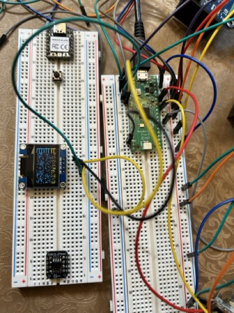
So, I picked a different tutorial and it worked with the following code:
include <Adafruit_SSD1306.h>
#include <Adafruit_GFX.h>

Adafruit_SSD1306 display(128, 64);

void setup() {
  display.begin(SSD1306_SWITCHCAPVCC, 0x3c);
  display.clearDisplay();
  display.setTextColor(WHITE);
  display.setTextSize(2);
  display.setCursor(0, 0);
  display.println("Raspberry pi pico");
  display.println("with OLED display");
  display.display();

}

void loop(){

}
And the OLED display worked:
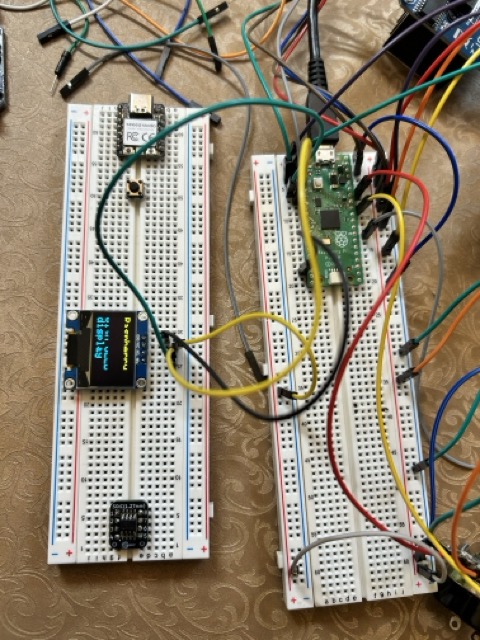
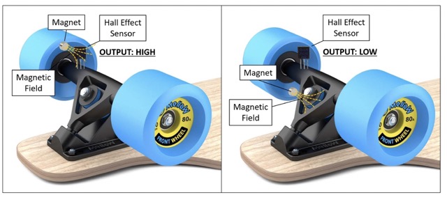
Hall Effect sensor
I will also include a hall effect sensor and a 0.96 OLED display to display the RPM of one of the wheels, as required by Mr. Dubick.
The Hall effect sensor works by detecting the magnetic field of a magnet and providing an output. To do this, I will put a magnet on the sie of the wheel, and attach the hall sensor to the bottom rail. This way, the hall sensor will detect the magnetic field when the magnet approaches it as the wheel turns. I got this idea from this research paper and this video.
Here is the photo:
Final code:
// OLED Display *********************************************************

#include <Adafruit_SSD1306.h>
#include <Adafruit_GFX.h>

Adafruit_SSD1306 display(128, 64);

// Red Motor *********************************************************

const int Red_RPWM = 0;
const int Red_LPWM = 1;
const int red_pot = 28;

const int sensor_threshold_red = 420;

// White Motor ******************************************************
const int White_RPWM = 3;
const int White_LPWM = 2;
const int white_pot = 27;

const int sensor_threshold_white = 370;

// Hall Sensor *********************************************************
// Define pin for Hall Effect Sensor
const int hallSensorPin = 6; // Use pin 15, which supports interrupts

volatile unsigned long pulseCount = 0; // Count of pulses
volatile unsigned long lastPulseTime = 0; // Time of the last pulse in microseconds
volatile unsigned long totalTimeBetweenPulses = 0; // Total time between pulses in microseconds

unsigned long previousMillis = 0; // To track the last RPM calculation time
const unsigned long interval = 1000; // Interval for calculating RPM in milliseconds
unsigned int rpm = 0; // Variable to store calculated RPM

// Interrupt service routine (ISR) for counting pulses and time between pulses
void countPulse() {
  unsigned long currentTime = micros(); // Get current time in microseconds
  if (lastPulseTime != 0) { // Ensure this is not the first pulse
    unsigned long timeBetweenPulses = currentTime - lastPulseTime; // Calculate time between pulses
    totalTimeBetweenPulses += timeBetweenPulses; // Accumulate the time between pulses
    pulseCount++; // Increment pulse count
  }
  lastPulseTime = currentTime; // Update last pulse time
}
//////////////////////////////////////////////////////////////

void setup() {

// OLED Display *******************

  display.begin(SSD1306_SWITCHCAPVCC, 0x3c);
  display.clearDisplay();
  display.setTextColor(WHITE);
  display.setTextSize(3);
  display.setCursor(0, 0);

// Hall sensor configuration *****************


  Serial.begin(9600); // Initialize serial communication
  pinMode(hallSensorPin, INPUT_PULLUP); // Set Hall effect sensor pin as input with pull-up resistor
  attachInterrupt(digitalPinToInterrupt(hallSensorPin), countPulse, FALLING); // Attach interrupt to sensor pin, trigger on falling edge

// Motors

  pinMode(Red_RPWM, OUTPUT);
  pinMode(Red_LPWM, OUTPUT);

  pinMode(red_pot, OUTPUT);
  pinMode(white_pot, OUTPUT);

  pinMode(White_RPWM, OUTPUT);
  pinMode(White_LPWM, OUTPUT);

}

void loop() {


// Red motor ***********************

  int redValue = analogRead(red_pot);
  Serial.print("red pot" + redValue);
  delay(1000);
  int whiteValue = analogRead(white_pot);
  Serial.println("white pot" + whiteValue);

// sensor value is in the range 0 to 1023
// the lower half of it we use for reverse rotation; the upper half for forward
// rotation
if (redValue >= 800){
  redValue = 800;
}

if (whiteValue >= 800){
  whiteValue = 800;
}

 controlMotor(Red_RPWM, Red_LPWM, redValue, sensor_threshold_red);
 controlMotor(White_RPWM, White_LPWM, whiteValue, sensor_threshold_white);

 // Hall-OLED ******************************************************************

  unsigned long currentMillis = millis(); // Get current time in milliseconds
  if (currentMillis - previousMillis >= interval) { // Check if it's time to calculate RPM
    if (pulseCount > 0) {
      // Calculate the average time per pulse in seconds
      double averageTimeBetweenPulses = (double)totalTimeBetweenPulses / pulseCount / 1000000.0;
      // RPM = (1 / average time per pulse in seconds) * 60
      rpm = (1 / averageTimeBetweenPulses) * 60;

      // Reset counters for the next interval
      pulseCount = 0;
      totalTimeBetweenPulses = 0;
    } else {
      rpm = 0; // If no pulses, RPM is zero
    }

    // Print RPM to serial monitor
    Serial.print("RPM: ");
    Serial.println(rpm);
    display.println("RPM: ");
    display.print(rpm);
    display.display();

    // Update the time for the next calculation
    previousMillis = currentMillis;
  }
display.clearDisplay();
display.setCursor(0,0);

}


// Controlling Red Motor ************************************

void controlMotor(int pwmPinForward, int pwmPinReverse, int sensorValue, int sensorThreshold){
  if (sensorValue < sensorThreshold){
    int reversePWM = -(sensorValue - sensorThreshold)/2;
    analogWrite(pwmPinReverse, reversePWM);
    analogWrite(pwmPinForward, 0);
  }
  else if (sensorValue > sensorThreshold){
    int forwardPWM = (sensorValue - sensorThreshold)/2;
    analogWrite(pwmPinForward, forwardPWM);
    analogWrite(pwmPinReverse, 0);
  }
}
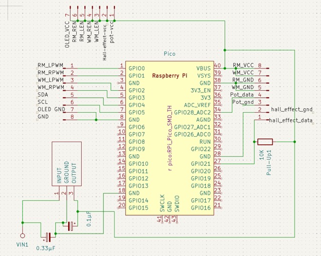
KiCAD design
Creating the design in KiCAD took many iterations, and the main problems with each design was:
- The fact that there were 2 Raspberry Pi Picos.
- Too much space.
- Too unorganized.
Originally, I decided to use 2 Raspberry Pi Picos since the potentiometer had the problem of cross-connection in which adjusting one pot affected the value of the other:
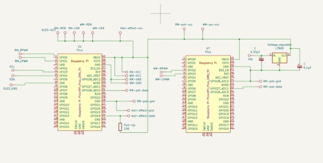
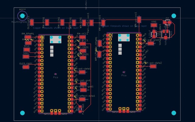
However, Mr. Dubick said that this was too space-consuming and I needed to shrink it down to just one board. So, I revised my design. This time, I made sure to put the pins together to create a neat row of them. The new design turned out neat:
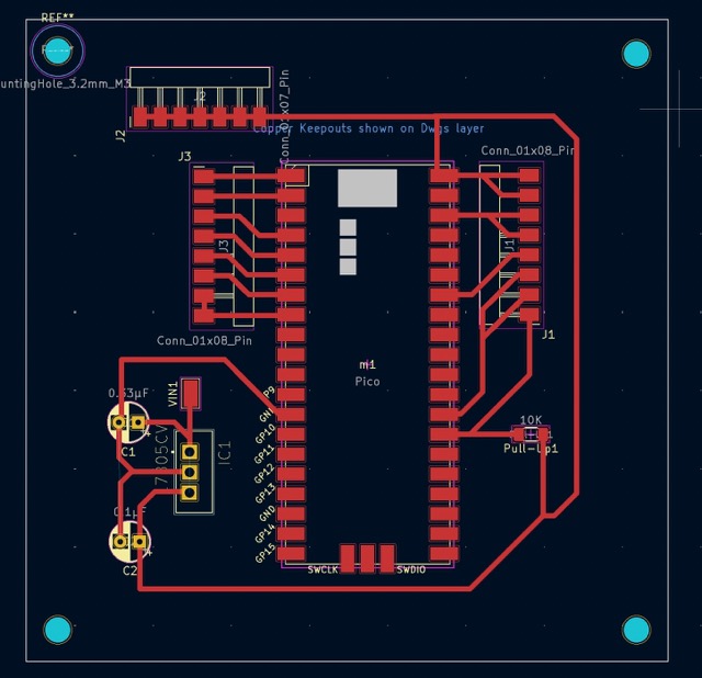
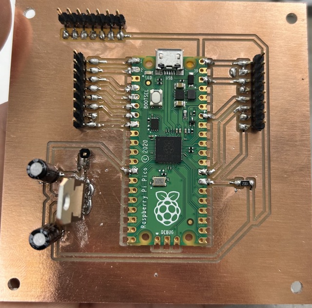
Milling out the board
Using the Bantam software and the Desktop CNC milling machine, I milled out my board on a copper board. Then, I soldered in the corresponding electronic pieces. The voltage regulator was hard to solder using a traditional soldering gun:
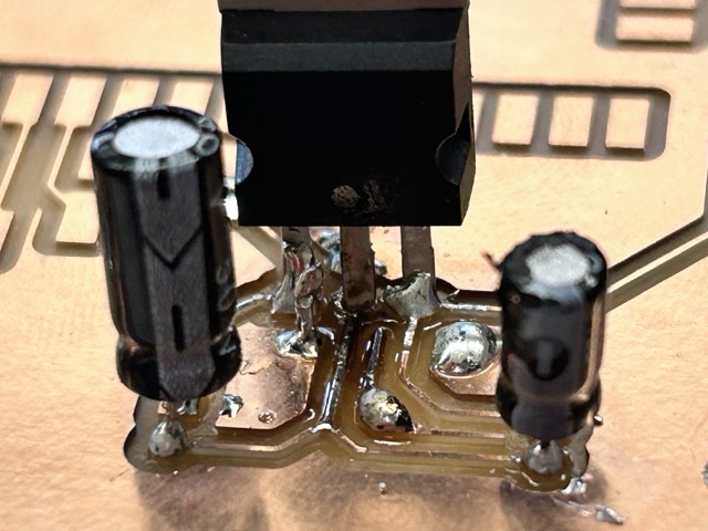
So, I used soldering paste and used a heat gun to heat up the paste, causing it to melt and completely solder the voltage regulator. I was afraid that the heat gun might break it, but luckily it didn’t overheat.
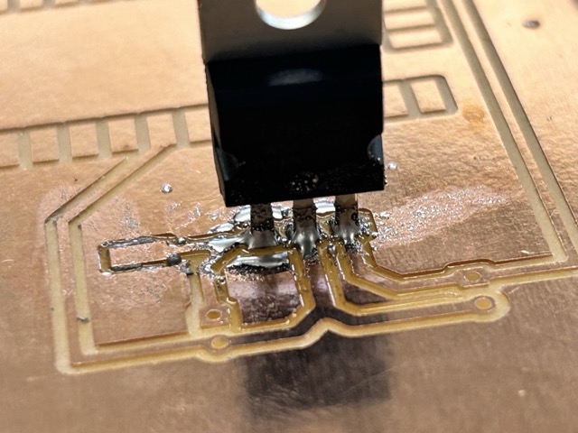
This was the entire board soldered:
Final Code on milled out board
Through an iterative process, I was able to get the code to work. Here is the final code:
#include <Adafruit_SSD1306.h>
#include <Adafruit_GFX.h>


Adafruit_SSD1306 display(128, 64);


const int Red_LPWM = 0;
const int Red_RPWM = 1;


const int pot = 28;


const int threshold = 250;


const int White_RPWM = 2;
const int White_LPWM = 3;


const int hallSensorPin = 15;


volatile unsigned long pulseCount = 0; // Count of pulses
volatile unsigned long lastPulseTime = 0; // Time of the last pulse in microseconds
volatile unsigned long totalTimeBetweenPulses = 0; // Total time between pulses in microseconds


unsigned long previousMillis = 0; // To track the last RPM calculation time
const unsigned long interval = 1000; // Interval for calculating RPM in milliseconds
unsigned int rpm = 0; // Variable to store calculated RPM


// Interrupt service routine (ISR) for counting pulses and time between pulses
void countPulse() {
 unsigned long currentTime = micros(); // Get current time in microseconds
 if (lastPulseTime != 0) { // Ensure this is not the first pulse
   unsigned long timeBetweenPulses = currentTime - lastPulseTime; // Calculate time between pulses
   totalTimeBetweenPulses += timeBetweenPulses; // Accumulate the time between pulses
   pulseCount++; // Increment pulse count
 }
 lastPulseTime = currentTime; // Update last pulse time
}


void setup(){


 display.begin(SSD1306_SWITCHCAPVCC, 0x3c);
 display.clearDisplay();
 display.setTextColor(WHITE);
 display.setTextSize(3);
 display.setCursor(0,0);


 Serial.begin(9600); // Initialize serial communication
 pinMode(hallSensorPin, INPUT_PULLUP); // Set Hall effect sensor pin as input with pull-up resistor
 attachInterrupt(digitalPinToInterrupt(hallSensorPin), countPulse, FALLING); // Attach interrupt to sensor pin, trigger on falling edge


 pinMode(Red_LPWM, OUTPUT);
 pinMode(Red_RPWM, OUTPUT);


 pinMode(White_RPWM, OUTPUT);
 pinMode(White_LPWM, OUTPUT);


 pinMode(pot, OUTPUT);


 Serial.begin(9600);
}


void loop(){
int Value = analogRead(pot);
Serial.print("Pot value: " + Value);


if (Value >= 500){
 Value = 500;
}


controlMotor(Red_RPWM, Red_LPWM, Value, threshold);
controlMotor(White_RPWM, White_LPWM, Value, threshold);


unsigned long currentMillis = millis(); // Get current time in milliseconds
 if (currentMillis - previousMillis >= interval) { // Check if it's time to calculate RPM
   if (pulseCount > 0) {
     // Calculate the average time per pulse in seconds
     double averageTimeBetweenPulses = (double)totalTimeBetweenPulses / pulseCount / 1000000.0;
     // RPM = (1 / average time per pulse in seconds) * 60
     rpm = (1 / averageTimeBetweenPulses) * 60;

     // Reset counters for the next interval
     pulseCount = 0;
     totalTimeBetweenPulses = 0;
   } else {
     rpm = 0; // If no pulses, RPM is zero
   }

   // Print RPM to serial monitor
   Serial.print("RPM: ");
   Serial.println(rpm);
   display.println("RPM: ");
   display.print(rpm);
   display.display();

   // Update the time for the next calculation
   previousMillis = currentMillis;
 }
display.clearDisplay();
display.setCursor(0,0);


}


void controlMotor(int pwmPinForward, int pwmPinReverse, int sensorValue, int sensorThreshold){
 if (sensorValue < sensorThreshold){
   int reversePWM = -(sensorValue - sensorThreshold)/2;
   analogWrite(pwmPinReverse, reversePWM);
   analogWrite(pwmPinForward, 0);
 }
 else if (sensorValue > sensorThreshold){
   int forwardPWM = (sensorValue - sensorThreshold)/2;
   analogWrite(pwmPinForward, forwardPWM);
   analogWrite(pwmPinReverse, 0);
 }
}