Processing GUI
I went to this tutorial to understand what a GUI is. It turns out that it usually consists of a pop up window that the user can interact with, such as pressing a button, adjusting a slider, etc. So, I decided to go ahead and use Processing. This tutorialexplains how to create a user interface using a simple LED. For me, I am going to extend this tutorial in order to create an interface with the DC motor circuit I built back in week 9.
LED Tutorial Code
First, I downloaded processing 4.2. Next, I built the circuit as described in the video:
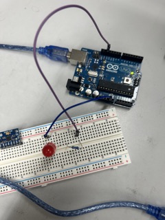
I also wrote the corresponding code as described in the tutorial. I learned that Serial.available() is a function that returns the number of bytes that are currently in the receiver buffer of the serial port. In other words, it allows you to determine if there is any incoming data that can be read without blocking the program execution.
Here is the code in the Arduino:
const int ledPin = 13;    //define the LED pin


void setup(){


  pinMode(ledPin, OUTPUT);    //initialize LED output
  Serial.begin(9600);         //start the serial communication
}


void loop(){


  if(Serial.available() > 0){           //if some data is available of in the serial port
    char ledPinState = Serial.read();   //read the value
    if(ledPinState == '1'){             //if statement will be true(1)
      digitalWrite(ledPin, HIGH);       //turn ON the LED
    }
    if(ledPinState == '0'){             //if statement will be false(0)
      digitalWrite(ledPin, LOW);        //turn OFF the LED
    }
  }
}
Here is the Processing code:
import processing.serial.*; //import the library for a serial communication

Serial myPort;             // define name of the serial communication

PImage bg;                 //Background image.Declare variable "bg of type PImage

void setup(){
  size(550, 844);
  bg = loadImage("redLED.png");

  myPort = new Serial(this, "/dev/cu.usbmodem101", 9600);
}

void draw(){
  background(bg);

  if (mousePressed && (mouseButton == LEFT)){
    myPort.write('1');
  }
  if (mousePressed && (mouseButton == RIGHT)){
    myPort.write('0');
  }

 }
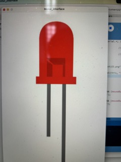
During this process, I learned that you can input a background image into the user interface, and that Processing can detect if you pressed the mouse on the left or right button. At first, when I ran the code, the background image did not show up. Then, I found the error:
ava.lang.RuntimeException:
This error says that the background image must be the same size as your application.
So, I changed the size of the image and made it 100 by 100 pixels. When that didn’t work, I went to the “get info” tab after right clicking on the image file. Then, I changed the size of the image to size(550, 844);, which is the actual size of the image. Now, the interface worked.
This is the LED interface:
For some reason, as I was trying to upload the code from the Arduino IDE, the Arduino programmer keeps saying that it is not responding. So, I asked ChatGPT why. It said that I needed to update the software, so that’s what I did. However, after restarting the software and unplugging and re-plugging the Arduino from my computer again, the code still didn’t work. So, I switched to a different Arduino. This time, it worked. The tutorial was complete.
This is the video of it working:
Re-affirming the motor code
Next, I made sure that my motor was still working after a while of not running it. I got a power jack, and revised my code:
int enA = 26;
int in1 = 27;
int in2 = 28;

int SpeedControl1 = 29;

// Motor Speed Values - Start at zero

int MotorSpeed1 = 0;

void setup() {
 // put your setup code here, to run once:

pinMode(enA, OUTPUT);
pinMode(in1, OUTPUT);
pinMode(in2, OUTPUT);

}

void loop() {

 digitalWrite(in1, HIGH);
 digitalWrite(in2, LOW);


 MotorSpeed1 = analogRead(SpeedControl1); // AnalogRead reads the values of the input from the potentiometer and see what the number is from 0 to 1023.

 MotorSpeed1 = map(MotorSpeed1, 0, 1023, 0, 255); // Then, we set the MotorSpeed to the analog input and map it.

 if(MotorSpeed1 < 10) MotorSpeed1 = 0;

 analogWrite(enA, MotorSpeed1); // Finally, we set the enA pin to the motorspeed obtained before.

}
This is the wiring:
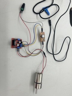
Then, after the code was uploaded to my XIAO, it worked.
Creating the Slider
Next, I have to generate a slider in Processing to make it interact with the motor. I searched up how to make a custom slider, and this tutorial helped me a lot.
I downloaded the controlP5 library from the list of libraries in Processing. To install the library, I referred to another this tutorial. But then, I wasn’t sure about implementing this library and the corresponding code as I figured that I could actually ask ChatGPT to generate the code of the slider for me, which would save a lot of time. I asked for the prompt, and here was the code for the basic shape:
int sliderPosition; // Variable to store the current position of the slider

void setup() {
  size(400, 200);
}

void drawSlider() {
  float sliderX = map(sliderPosition, 0, width, 20, width - 20); // Calculate the x-coordinate of the slider based on its position

  // Draw the track
  stroke(0);
  line(20, height / 2, width - 20, height / 2);

  // Draw the slider button
  fill(255);
  rectMode(CENTER);
  rect(sliderX, height / 2, 10, 20);
}

void draw() {
  background(220);
  // Draw the slider
  drawSlider();
  // Do other drawing and updates here
}
The problem is that I didn’t really understand the code, and when I asked ChatGPT what it meant, it gave me a summary of the description:
The line float sliderX = map(sliderPosition, 0, width, 20, width - 20); calculates the x coordinate of the slider based on its current position, represented by sliderPosition. The sliderPosition is a number between 0 and the width of the window. The 20, width-20 is the range in which the x-coordinate of the slider can be in. So, 20 acts as a buffer zone between the side of the interface and the two ends of the slider.
The line line(20, height / 2, width - 20, height / 2); draws the line at the midpoint of the window, and extends from positive 20 to width-20.
These are the most important lines of code in the segment.
Next up is the user interface part, in which the mouse can be used to slide the button up and down, which is also provided by ChatGPT:
void mousePressed() {
  // Check if the mouse is within the bounds of the slider button
  float sliderX = map(sliderPosition, 0, width, 20, width - 20);
  float sliderY = height / 2;
  float buttonWidth = 10;
  float buttonHeight = 20;

  if (mouseX > sliderX - buttonWidth / 2 && mouseX < sliderX + buttonWidth / 2 &&
      mouseY > sliderY - buttonHeight / 2 && mouseY < sliderY + buttonHeight / 2) {
    // Set a flag to indicate that the slider is being dragged
    isDraggingSlider = true;
  }
}

void mouseReleased() {
  // Reset the dragging flag when the mouse is released
  isDraggingSlider = false;
}

void mouseDragged() {
  if (isDraggingSlider) {
    // Update the slider position based on the mouse's x-coordinate
    sliderPosition = constrain(mouseX, 0, width);
  }
}
Basically, the segment checks to see if the mouse is within the bounds of the slider button, and makes the boolean variable of isDraggingSlider equal to true. This allows the button to move.
I changed isDraggingSlider to a global variable and rearranged the functions provided by ChatGPT, placing the void draw() at last. In the end, the completed code is as follows:
int sliderPosition; // Variable to store the current position of the slider
boolean isDraggingSlider = false;

void setup() {
  size(400, 200);
}

void drawSlider() {
  float sliderX = map(sliderPosition, 0, width, 20, width - 20); // Calculate the x-coordinate of the slider based on its position

  // Draw the track
  stroke(0);
  line(20, height / 2, width - 20, height / 2);

  // Draw the slider button
  fill(255);
  rectMode(CENTER);
  rect(sliderX, height / 2, 10, 20);
}

void mousePressed() {
  // Check if the mouse is within the bounds of the slider button
  float sliderX = map(sliderPosition, 0, width, 20, width - 20);
  float sliderY = height / 2;
  float buttonWidth = 10;
  float buttonHeight = 20;

  if (mouseX >= sliderX - buttonWidth / 2 && mouseX <= sliderX + buttonWidth / 2 &&
      mouseY >= sliderY - buttonHeight / 2 && mouseY <= sliderY + buttonHeight / 2) {
    // Set a flag to indicate that the slider is being dragged
    isDraggingSlider = true;
  }
}

void mouseReleased() {
  // Reset the dragging flag when the mouse is released
  isDraggingSlider = false;
}

void mouseDragged() {
  if (isDraggingSlider) {
    // Update the slider position based on the mouse's x-coordinate
    sliderPosition = constrain(mouseX, 0, width);
  }
}

void displayValue() {
  fill(0);
  textAlign(CENTER, CENTER);
  text(sliderPosition, width / 2, height / 2 + 30);
}


void draw() {
  background(220);
  // Draw the slider
  drawSlider();
  // Display the value
  displayValue();
}
It works!
Implementation of Motor
Following the inspiration from the previous LED example, in which the code checks to see if Serial.available() is equal to 1 or 0. I realized I can do the same thing with my motor. If the slider button is pressed in Processing, then the motor would spin, and its speed would be adjusted by the slider.
In Processing, I imported:
import processing.serial.*; // import library for a serial communication

Serial myPort; // Name of port
This way, Processing can communicate with the Arduino IDE. Next, I included myPort.write(sliderPosition); to give the slider position to the port, when Processing detects that the slider is sliding.
In the Arduino IDE, I commented out the speed control, i.e. the potentiometer and switched that section for:
if (Serial.available() > 0){
   Serial.println(Serial.available());
 }
I wanted to test if the serial monitor can print out the slider position.
However, I keep getting the error that says the port is busy. Then, I restarted the computer, and the port still indicated that it was busy. I even tried installing the new updates in Arduino IDE, but it still did not work.
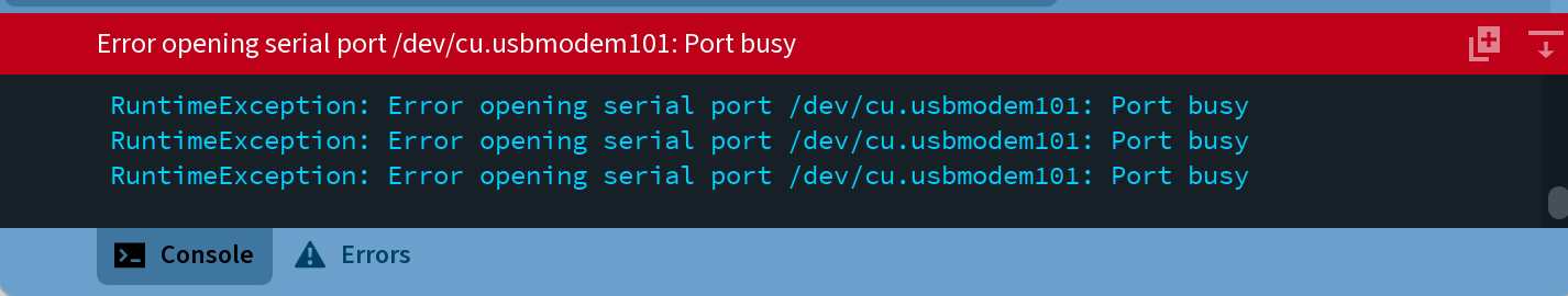
After a while, I noticed that Processing would work fine if I use the /dev/cu.usbmodem101 port, and it does not report the port not found error or the port busy error. However, the 2 ports are not the same because the Arduino IDE would be using the Bluetooth-Incoming-Port, so the slider cannot control the motor.
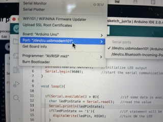
Then, I reverted back to the Arduino example and tested that with the Arduino Uno again, I found that the code worked.
When the problem has continued for a while, I asked Merrit Backerman for help. He said that the problem for me is that I was using the Serial Monitor in the Arduino IDE. Since I am physically viewing it from the software, the serial port is busy, as it is outputting values onto a specific interface. Therefore, Processing cannot run on the same port when the serial monitor is open. Originally, I planned to use the serial monitor to ensure that the slider values can be outputted. Now, it looks like I have to move directly to controlling the motor with the slider.
So, here is the updated void loop() in Arduino IDE:
void loop() {

 SliderPos = Serial.read();

 if (SliderPos >= 0){
   MotorSpeed1 = map(SliderPos, 0, 750, 0, 255);
   if (MotorSpeed1 < 10){
     MotorSpeed1 = 0;
   }
 }
 analogWrite(enA, MotorSpeed1);

 }
This website tells me exactly what to do. I had to import ControlP5 after all.
This is the modified Processing code to make the slider using the library:
import controlP5.*;

ControlP5 MyController;

Slider mySlider;

void setup(){
  size(500,400);
  MyController = new ControlP5(this);

  mySlider = MyController.addSlider("Motor Controller", 0, 255, 0, 20, 200, 360, 30);
  mySlider.setColorBackground(color(44, 41, 207));

}
At first, I could not get the background color correct, but this website taught me how by changing the function name.
This is the new slider code:
import controlP5.*;

import peasy.*;
import processing.opengl.*;

PeasyCam cam;

PMatrix3D currCameraMatrix;

PGraphics3D g3;

ControlP5 MyController;

Slider mySlider;

void setup(){
  size(500,400, OPENGL);
  g3 = (PGraphics3D)g;
  MyController = new ControlP5(this);

  cam = new PeasyCam(this, 200, 300, 100, 500);

  mySlider = MyController.addSlider("Motor Controller", 0, 255, 90, 20, 200, 360, 30);
  mySlider.setColorBackground(color(44, 41, 207));
  mySlider.setColorForeground(color(88, 173, 152));
  mySlider.setColorActive(color(44,140,209));
  mySlider.setColorLabel(color(0, 0, 0));

  MyController.setAutoDraw(false);
}

 void gui(){
  currCameraMatrix = new PMatrix3D(g3.camera);
  camera();
  MyController.draw();
  g3.camera = currCameraMatrix;
}

void draw(){

  background(163, 104, 163);
  noFill();
  stroke(20);
  pushMatrix();
  translate(250, 300, 20);
  sphere(200);
  popMatrix();
  gui();
}
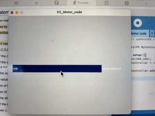
This is the new slider GUI:
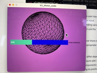
As you can see, I also made the interface 3D and interactive, with a sphere to prove that it is indeed 3D. The camera is set in a planar view from the side. The slider works and the code is a lot more readable. To get the current value of the slider, I just write myslider.getValue.
This is complete code after adding the obtaining the current value functionality:
import processing.serial.*;

Serial myPort;

import controlP5.*;

import peasy.*;
import processing.opengl.*;

PeasyCam cam;

PMatrix3D currCameraMatrix;

PGraphics3D g3;

int SliderVal;

ControlP5 MyController;

Slider mySlider;

void setup(){
  size(500,400, OPENGL);
  g3 = (PGraphics3D)g;
  MyController = new ControlP5(this);

  cam = new PeasyCam(this, 200, 300, 100, 500);

  mySlider = MyController.addSlider("Motor Controller", 0, 255, 0, 20, 200, 360, 30);
  mySlider.setColorBackground(color(44, 41, 207));
  mySlider.setColorForeground(color(88, 173, 152));
  mySlider.setColorActive(color(44,140,209));
  mySlider.setColorLabel(color(0, 0, 0));

  MyController.setAutoDraw(false);
  myPort = new Serial(this, "/dev/cu.usbmodem101", 9600);
}

 void gui(){
  currCameraMatrix = new PMatrix3D(g3.camera);
  camera();
  MyController.draw();
  g3.camera = currCameraMatrix;
}

void draw(){

  background(163, 104, 163);
  noFill();
  stroke(20);
  pushMatrix();
  translate(250, 300, 20);
  sphere(200);
  popMatrix();
  gui();

  SliderVal = (int) mySlider.getValue();

  println(SliderVal);

  myPort.write(SliderVal);
}
I have added the port, and casted the current value to an integer, because you cannot write a double-type variable to a port. As you can see here, when I am adjusting the slider, the positions are being printed out and the sphere is turning.
The Processing interface now works perfectly, but I suddenly had trouble uploading my modified Arduino sketch. So, I closed the program and restarted it, prompting it to work.
Now, even after all of my progress, the motor still does not turn. So, I tested to see if the RP2040 was receiving any messages at all by writing these lines of code in the Arduino IDE:
if (Serial.read() > 0){
   analogWrite(enA, 200);
 }

 else if (Serial.read() <= 0){
   analogWrite(enA, 100);
 }
However, the motor does not spin, regardless of Serial.read()’s state. So, now I am doubting that the Arduino IDE is interacting with Processing at all.
I suspected that it was due to some hardware issue. I took out my multimeter and tested every connection along my circuit, but all seems fine.
I even switched for a different RP2040 by de-soldering the original one with a heat gun and replacing it:
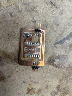
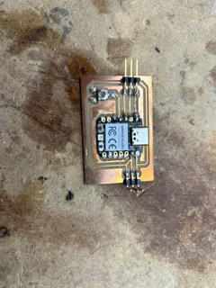
However, the motor still does not spin when I upload both codes.
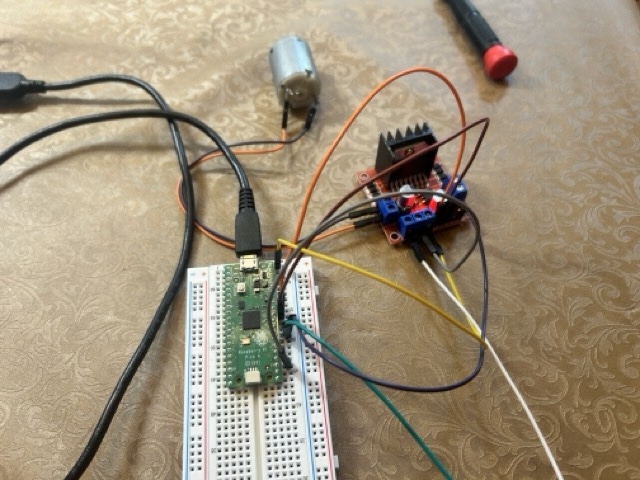
I decided to switch to a breadboard so that the connections would be more secure and stable.
This is the new wiring:
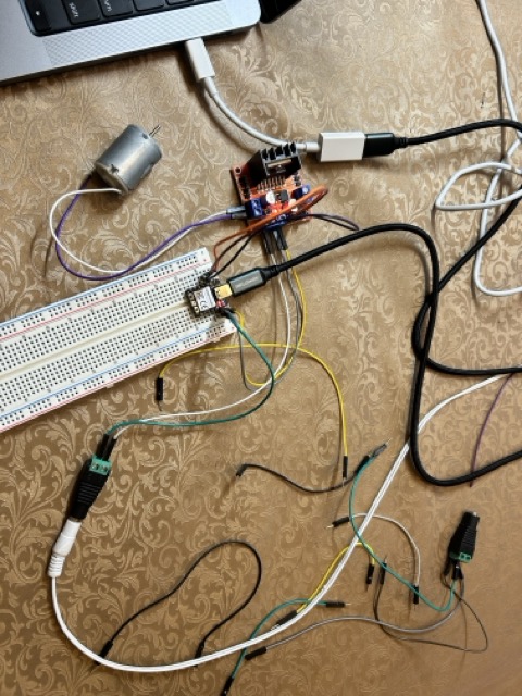
I tested the motor to see if it works, and it does:
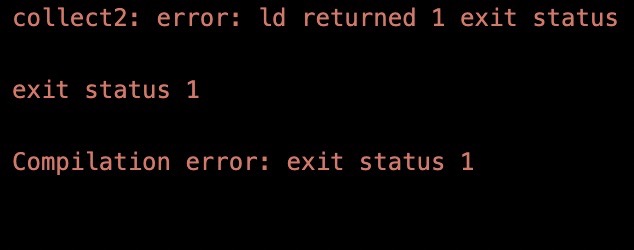
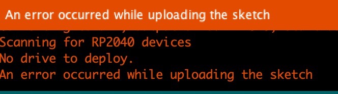
When I ran the Processing code again, however, Process keeps saying the port is busy, even though I was not using the serial monitor. So then I tried to shut everything down and rebooted it a couple minutes later. When I uploaded the code on Arduino IDE, it have me the following error:
error adding symbols: no more archived files - error on Arduino IDE. Exit status 1
Even though I updated the Arduino to version 2.2, the code still wouldn’t upload. It couldn’t have been that it wasn’t connected because according to the usb tree, it is:
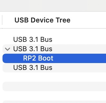
So I switched to the older version of the IDE, and the code uploaded!
However, the motor still doesn’t spin.
Sometimes, the port is busy, and both Processing and Arduino IDE cannot function properly:

Whenever this happens, I rebooted the softwares again.
Having trouble, I went back to the demo code and examined it again:
int enA = 7;
int in1 = 5;
int in2 = 4;

void setup() {
  // put your setup code here, to run once:

pinMode(enA, OUTPUT);
pinMode(in1, OUTPUT);
pinMode(in2, OUTPUT);
Serial.begin(9600);
}


void demoOne(){
  // This will run the motor in both directions at a fixed speed.

  digitalWrite(in1, HIGH);
  digitalWrite(in2, LOW); // initiation, and spinning it clockwise
  analogWrite(enA, 200);

  delay(2000);

 digitalWrite(in1, LOW);
  digitalWrite(in2, HIGH); // turn it the other way.
  delay(2000);
  digitalWrite(in1, LOW);
  digitalWrite(in2, LOW);
}

void demoTwo(){
  digitalWrite(in1, HIGH);
  digitalWrite(in2, LOW);

  for (int i = 0; i < 256; i++){
    analogWrite(enA, i);
    delay(20);
  }

  for (int i = 255; i>= 0; --i){
    analogWrite(enA, i);
    delay(20);
  }
  digitalWrite(in1, LOW);
  digitalWrite(in2, LOW);
}


void loop() {
  // put your main code here, to run repeatedly:
demoOne();
delay(1000);
demoTwo();
delay(1000);
}
After all this time, I realized I was missing the crucial:
 digitalWrite(in1, HIGH);
   digitalWrite(in2, LOW); // initiation, and spinning it clockwise
By not specifying a direction, I was not able to get the motor to spin. I implemented this part in my Arduino code, simplified it a little bit to match that of the LED tutorial code, and here is my final result:
FINAL Arduino Code:
#include <String.h>

int enA = 26;
int in1 = 27;
int in2 = 28;


String SliderPos;

unsigned long previousMillis = 0;
const unsigned long interval = 50;

 // int SpeedControl1 = 29;

// Motor Speed Values - Start at zero

int MotorSpeed1 = 0;

void setup() {
  // put your setup code here, to run once:

pinMode(enA, OUTPUT);
pinMode(in1, OUTPUT);
pinMode(in2, OUTPUT);
Serial.begin(9600);

}

void loop() {

  digitalWrite(in1, HIGH);
  digitalWrite(in2, LOW);

  if (Serial.available() > 0){
    SliderPos = Serial.read();
    MotorSpeed1 = SliderPos.toInt();
    analogWrite(enA, MotorSpeed1);
  }

  }
Note that serial.read() is going to read the Processing data as a series of strings, and that I need the toInt() command to turn them into integers.
Final Processing Code:
import processing.serial.*;

Serial myPort;

import controlP5.*;

import peasy.*;
import processing.opengl.*;

PeasyCam cam;

PMatrix3D currCameraMatrix;

PGraphics3D g3;

int SliderVal;

ControlP5 MyController;

Slider mySlider;

void setup(){
  size(1300,800, OPENGL);
  g3 = (PGraphics3D)g;
  MyController = new ControlP5(this);

  cam = new PeasyCam(this, 200, 300, 100, 500);

  mySlider = MyController.addSlider("Motor Controller", 0, 230, 0, 20, 200, 360, 30);
  mySlider.setColorBackground(color(44, 41, 207));
  mySlider.setColorForeground(color(88, 173, 152));
  mySlider.setColorActive(color(44,140,209));
  mySlider.setColorLabel(color(0, 0, 0));

  MyController.setAutoDraw(false);
  myPort = new Serial(this, "/dev/cu.usbmodem2101", 9600);
}

 void gui(){
  currCameraMatrix = new PMatrix3D(g3.camera);
  camera();
  MyController.draw();
  g3.camera = currCameraMatrix;
}

void draw(){

  background(163, 104, 163);
  noFill();
  stroke(20);
  pushMatrix();
  translate(250, 300, 20);
  sphere(200);
  popMatrix();
  gui();

  SliderVal = (int) mySlider.getValue();

  println(SliderVal);

  myPort.write(SliderVal);
}
Raspberry Pi Pico
Then, later on, I switched my microcontroller to a Raspberry Pi Pico because I am using a Pico for my final project, and I wanted this project to mimick my final project for preparation purposes. The wiring is pretty much the same, I just had to change the pin numbers for the EnA, in1, and in2 pins to the corresponding GPIO pins on the Pico. Here is the wiring:
In the final result, everything worked. As you can see in the video, the red tape wrapped around the motor indicates that its speed changes with my slider: