Milling Process
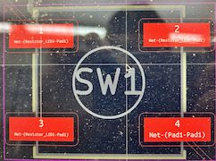
From the design file I created for week 6 (which was just a basic LED program with a resistor, the Xiao board, and the LED, I plotted the files in KiCAD by selecting the front copper and edge cut files. The F.CU file basically cuts out the actual design, while the Edge cuts file cuts out the rectangle for the board.
Footprint changes
After making some precise measurements of the electrical components I planned to solder on to my board, I realized that some of my previous footprints were incorrect.
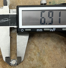
The button footprint was kept the same:
I reached this conclusion after figuring out the width and length of the button and matching those numbers to the actual dimensions:
(Note that the units are in mm).
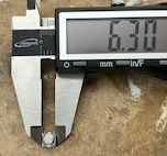
Then, I measured the width and lengths for each of the resistors:
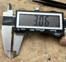
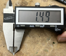
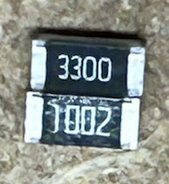
The 330 ohm resistor and the 10K ohm resistors had the same dimensions:
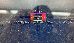
So, I changed the footprints for both resistors:
I realized that the length of this footprint best matches that of the actual resistor (which turned out to be wrong, as you will see below).
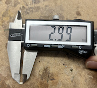
Next, it is time to measure the LED:
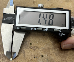
Based on these measurements, I changed the LED footprint as well:
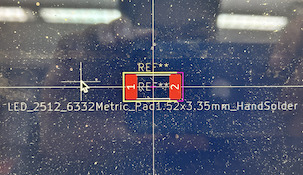
In KiCAD, I swapped the current footprints with the newly found ones described above.
Bantam procedure
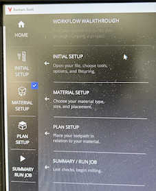
Next, it is time to set up the Bantam software. Following a recent update, the software has made the process a lot easier. Now, there is a workflow in the interface:
The initial setup consists of importing the Front copper and edge cuts files from Google drive. Note that they are both Gerber files.

Since, I am only soldering surface-mounted electrical components, I didn’t need holes to be cut on my board. Thus, I deselected the Holes option so that it appears as <none>.
Next, I placed the one sided copper board onto the Othermill machine. I first attached nitto tape on the non-copper side and peeled the adhesive away. Next, I lined up the board with the lower left corner of the Othermill machine and pressed it down firmly so that it does not move.
The next step in the Bantam workflow is to measure the stock, or the material to cut:
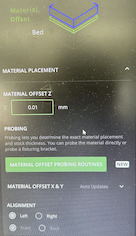
The offset of 0.01 mm accounts for the thickness of the nitto tape.
The green button that mentions “probing” essentially sends the bit of the machine down to the copper board.
I first place a conductor in the form of a switch onto the copper board. Next, as the bit slowly moves towards the stock, an electric current is generated as soon as it touches the copper. Now, the machine knows where the copper board is.
The machine then calculates the height of the stock –> but before it can do that, it needs another variable: the height of the bed itself:
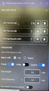
This is the tool installation tab, where I selected the tool that I wanted to use. In this case, I used a “1/64 flat end mill”, a “1/32 flat end mill”, and a “PCB Engraving Bit 0.005’‘“. After selecting the tool, the machine would send the tool bit down to the bed, not to the stock. As soon as the bit touches the metal bed, it knows the position of the bed.
Since it also knows the position of the stock, it is able to figure out the height of the copper board that I am using through subtraction.
Milling
Then, I checked off the other procedures on the Bantam workflow (you can check it out in my group site). This includes having a trace depth of 0.2mm and a trace clearance of 1.5mm. I also selected “trace” and “outline” for the front copper file, and selected “outline” for the edge cuts file.
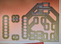
This is the current rendition of my design in Bantam:
After checking that everything is good, I proceeded to mill out the board. The bit goes spinning at thousands of RPM, and away it goes.
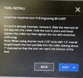
Throughout the process, the machine would pause and require me to switch bits, which I would do carefully, making sure not to break the bits’ pointy ends:
Milling Trouble
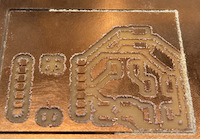
The first mill actually went wrong:
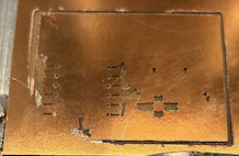

These pictures show an unfinished cut of my board. This meant that the board itself was not measured correctly. After consulting Mr. Budzichowski’s help, I noticed that the copper board was very bumpy. The nitto tape at the bottom had pieces of metal stuck to it, which did not make the board perfectly flat. Thus, only a part of the board was cut.
I also realized that I selected “outline” for front copper, which was a mistake as it was unnecessary. So, I deselected it and made another rendition in Bantam:
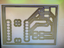
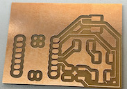
I tried a new board, and the cut worked out well.
Milled out board
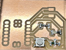
This is the cut board:
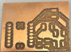
I then deburred the boards so that they have a smoother finish. This is really simple as I just used the edge of a another copper board and scaped off the rough bits of my board. This is the deburred board:
Soldering process
Now, it is time to solder on the electrical components. Remember that I mentioned the footprints for the resistors are wrong? Well, it turned out that it was actually twice the correct length.
In order to fix this problem, I used a 0 ohm resistor as a connector. I first soldered on side of the connector to one copper pad, and its other side to the 10K/330 ohm resistor. Then, I finished the connection by soldering the resistor’s end to the other copper pad:
(The connector is the green piece).
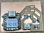
This is the first half of the board soldered:
This is the completed board:
Trace problem
The first time I tested the board, the LED didn’t light up. So, I used the Arduino IDE to test if the digital pin on the Xiao works properly. The serial monitor was giving outputs, so I knew that the pin was working:
Thus, this meant that the LED didn’t work. So, I switched for a different one.
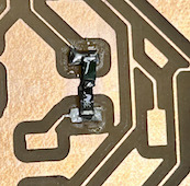
I desoldered the broken LED, and almost ripped the trace:
As you can see, I overheated the board, and parts of the copper came off.
However, I was able to put that copper piece back on with the soldering iron, and switched for a different LED.
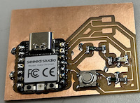
Finished product
Now, the board fully works, and here is my finished product:
Source code
Here is the code I used for the blink LED light program:
// the setup function runs once when you press reset or power the board
void setup() {
  // initialize digital pin LED_BUILTIN as an output.
  pinMode(3, OUTPUT);
  pinMode(4, INPUT);
}

// the loop function runs over and over again forever
void loop() {
  bool button_press = digitalRead(4);
  if (button_press == true){
    digitalWrite(3, HIGH);
  }
  else{
    digitalWrite(3, LOW);
  }
}