3D printing and Scanning
Visual Studio code IDE
The following is a separate issue:
As I started to work on my individual part, I first downloaded and installed the visual studio IDE (the file was really large so it took a while). Fellow Fab Academy student Adam Durrett told me about the advantages of this IDE, as it can effortlessly switch between languages and customize tools easily.
However, I did not realize that this IDE is not free on Mac. So, I just quit using it.
Prusa Slicer
GitHub recently released the 2.6 version of PrusaSlicer, a software that produces the g-code of a fusion 360 .stl file. I got it from this creator. But, I decided to use the current version of 2.5 because I can access it more directly than 2.6, as they have not made an app for it yet.
Anti-subtractive design
In order to make an anti-subtractive design in Fusion 360, I have to first understand the difference between additive and subtractive design: this website helped a lot. One of the limitations of subtractive manufacturing is that it cannot create enclosed objects like a hollow box.
My initial plan is to create a box within a box within a tetrahedron. But soon I realized that this was not practical.
So I decided to switch gears and create a gear and a gear holder that would later be used as a potentiometer in my tennis ball machine. The control panel will be consisted of 2 scroll wheels that could adjust the speed of the tennis balls shooting out of the machine, as well as the feed rate.
The purpose of this is to visualize my control panel.
I started with a circle on the xy plane and sketched out the teeth of the gear.
I also defined user parameters (they didn’t come particularly useful as I had to constantly adjust them).
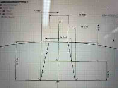
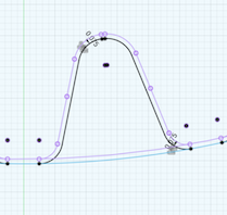
First, I made the circle’s diameter as a construction line. Then, I made 2 parallel lines that intersected the construction line at their midpoints. After connecting the endpoints together, I have a trapezoid.
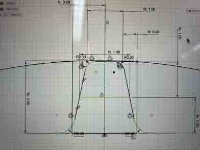
Then, I used the filet tool to round the edges:
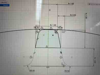
As you cans see in the above picture, there upper half of the shape is redundant, so I deleted it:
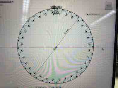
These are the dimensions of the gear. I had to visualize it as there were no existing gear to measure off on:
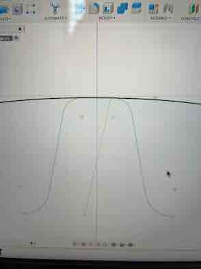
Finally, this is the completed gear teeth in the sketch palette:
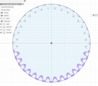
Then, I used the circular pattern feature, selected the teeth as my profile, the center of the circle as the rotating point, and set the number of teeth to 33. This created the basic outline of the gear.
Next, I just extruded the gear by 5 mm to make it solid:
I also extruded and cut some holes in the center of the gear and along the edges.
Now, I just have to make the holder for the gear. First, I tried to offset (using the offset feature) the gear teeth by 0.075 mm to account for friction/fit. But, I accidentally offset it the wrong way (inside the circle).
So, I had to delete that offset.
Because I wanted the gear holder to be almost halfway around gear, I had to offset a lot of curves. I undertook the tedious task of selecting over 100 curves to offset, which took a while:
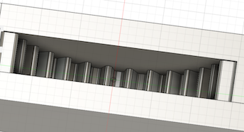
Next, I used the offset feature to offset all the curves by 0.075mm, and created a rectangular gear holder with teeth beneath the gear. After an extrusion of 7.5 mm (leaving a 1.25mm brim on each side after the gear is put in), I have a completed gear holder:
This is the top view:
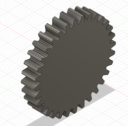
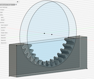
Then, I turned the visibility icon of the gear back on and here is the final product:
To print the gear, I first have to have to upload my Fusion 360 design as a .stl file into PrusaSlicer, a software that generates G codes of the designs.
However, several of my prints were ripped off from the 3D printer as the base layer was not sturdy enough. As a result, the entire print failed.
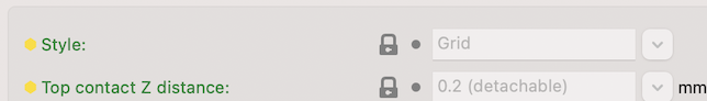
To solve this problem, I went into the printer’s settings and expanded the distance between the nozzle and the print bed by about 0.2mm, and then it worked. This was because the distance was too small, and the print was ripped off from the bed by the nozzle.
Fellow student Merritt Backerman showed me how to change different support types in the print settings, such as grid, tree, natural, and snug. The snug supports are thinner and come up easier than the regular grid supports, which could be helpful when printing a design that needed a lot of supports.
This is the page for changing supports:
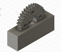
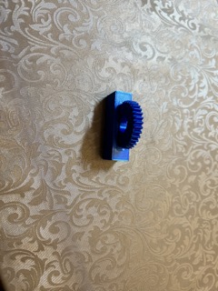
After the print was successfully printed, the gear holder didn’t work as intended, because I failed to consider one aspect. The teeth interlocks themselves together and create friction. Thus, I wasn’t able to spin the gear in the gear holder like I thought I would.
Here is the final product:
3D scanning
The purpose of 3D scanning is to scan a physical object in the real world and give it a 3D render so that
First, this website explained the app for 3D scanning, and then printing the resulting model.
Next, I downloaded the PolyCam app in orde to scan my water bottle.
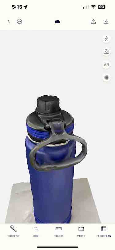
However, I cannot export this rendition to PrusaSlicer as an STL format because it’s a paid service. So, I tried to export it as a GLTF file and convert that into an STL.
However, the online file converter failed to convert the file, so I visited a new website and downloaded their software. However, when I tried to upload the converted STL file into Fusion 360 and Prusa slicer, it said that the file is corrupted for some reason.
So, I asked Merritt again for help. I followed his advice and downloaded a new app: KIRI Engine. I used the free version and it only limited me to taking 70 pictures of a remote controller for a TV, but the .stl conversion failed because the app claimed that the way I took the images was wrong. So, I tried again.
The failed version looked like this:
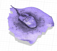
I tried again and Merritt pointed out that I needed to scan something that is not reflective. I opted for a computer mouse and here is the result:
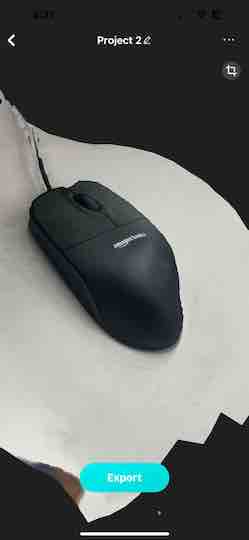
To scan an object, I basically walk around it 360˚ very slowly and make sure to take a picture at every angle possible, or whenever I scan a different location.
I exported the file the .stl file into Fusion360.
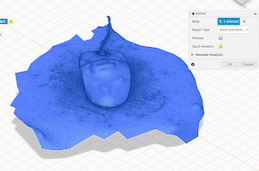
Next, I used the repair mesh body tool in order enclose the model, as it was completely unclosed at the bottom:
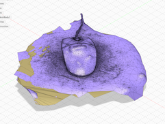
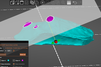
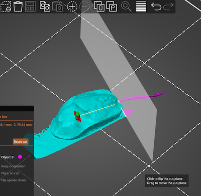
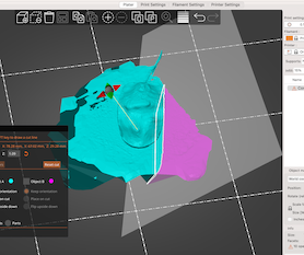
But the bottom part not jutted out and formed an excessive mound. So, in PrusaSlicer, I used the cut tool in order to get rid of excessive parts. I was able to rotate the model and shift the plane in order to get rid of extraneous parts.
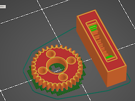
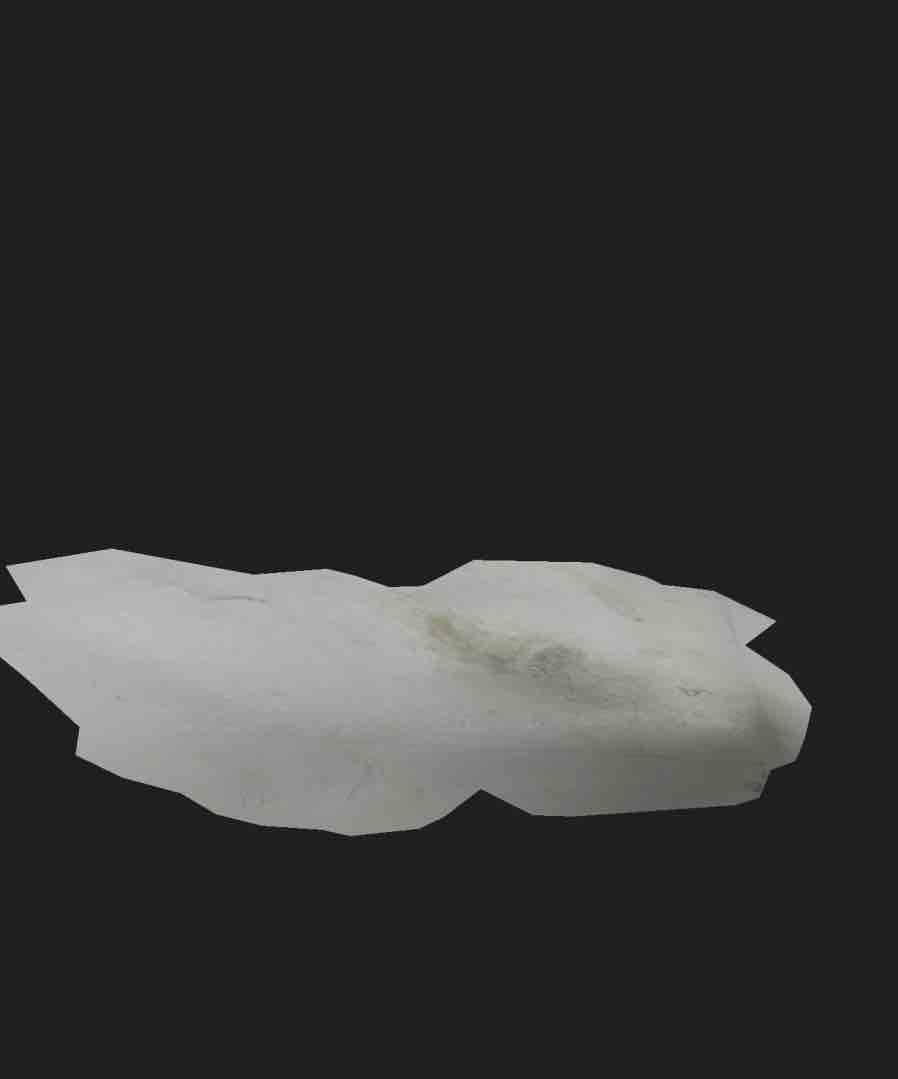
Next, sliced my model and used the g-code to print the design, which looks like this:
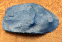
For the Future
As you might have noticed in the picture, the printed mouse was far from perfect. On top of it, there were flat areas that are cut in PrusaSlicer, giving it an unnatural feel. I believe that tif I had more time, I could have rounded the edges a little bit more and maybe designed some sort of plastic covering in order to smooth out the rough edges.