Laser cutter group project
As a quick overview of our group project, we basically characterized the laser cutter in terms of its speed, power, and frequency. Putting the objects we want to cut using the laser cutter inside an array with increasing parameters of speed, power, and frequency of the laser cutter, we were able to complete the project.
- We also analyzed the kerf of the laser cutter (the area blasted away by the laser beam).
- We analyzed the effect of dithering of the laser cutter, which creates an image by using quick beams of light and cutting small holes in the material.
- Focus is the degree in which the image/object is projected onto the material. We could adjust it in the laser cutter’s settings.
- Joint clearance is about finding the optimal size of the joint of a material so that they connect.
More information on the group project could be found here.
Parametric Design
For my individual project this week, I made a parametric design in Fusion 360 and used the laser cutter to cut it out.
The definition of a parametric design is to use the user parameters feature in the software. It basically allows you to set your own dimensions. Then, you can go back and change them. If the constraints were set correctly, then the entire design would change correspondingly, to the same ratio as you changed your dimensions.
As you can see in the picture below, I have a table dedicated to setting my own user parameters.
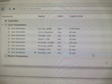
I have everything labeled in the table, and so I can just refer to these variables and build equations with them to set the dimensions.
Building the shapes
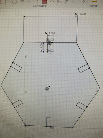
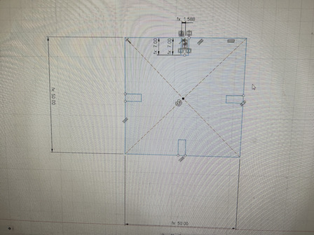
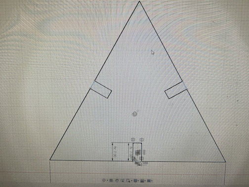
I designed several regular polygons and a rectangle. Most of the polygons are regular polygons, and as you can see, have a joint connector on each side of the polygon. To make these joints, I first created a construction line (keyboard shortcut x) in the midpoint of a side of the polygon. Then, I used the user parameter (cut width/2) to build 2 lines on either side of the construction line (both are cut depth long). Then, I used the circular pattern feature to create all the other joints in the shape. I simply set the quantity to the number of sides and selected the center of the polygon as the rotating point.
The dimension of each cutout are labeled in the regular hexagon:
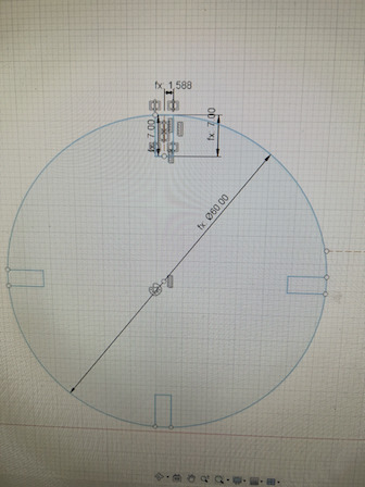
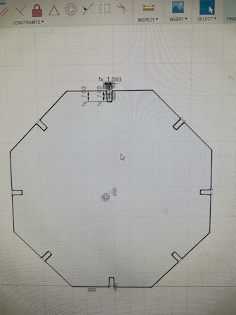
The shapes that I built are as follows:
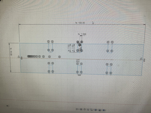
The rectangle was a bit different, as there were 3 joints on each side. So, I just used the rectangular pattern feature to create the joints on either side of the center (midpoint) joint on each length of the rectangle.
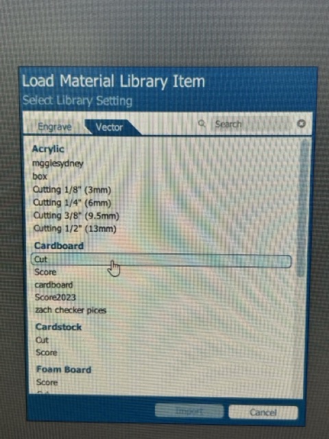
Coreldraw
To export the design files into CorelDRAW, I first put them into the shared engproj folder by exporting them as .dxf files. This format ensures that they are exported as 2D instead of 3D. Then, I downloaded them into CorelDRAW and went to the large laser cutter to cut them out. This part required no special adjustments, except for the fact that the vectors all had to be set to 0.001 inch or “hairline” in order to be laser cut.
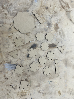
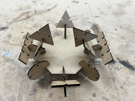
Then, I built a what I called an outer-space platform using the materials I have.
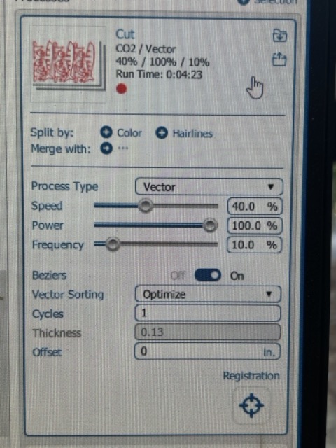
Settings
These are the settings I used for the laser cutter:
Improvement
As fellow student Griffin Orsinger later pointed out, the joints were indeed a bit hard to put in. So, next time I could have put a chamfer on the individual joints so that they are easier to put in. A chamfer is different from a traditional fillet because it creates an extra edge on an existing edge (Essentially a 45 degree edge). This auxiliary edge smoothes out the existing edge and makes it easier to connect.
As I viewed fellow student Adam Stone’s website, I could have also played around with the shape of the joints. Instead of making a simple joint that only composes of a rectangular shape, I could have went to Cuttle, and then made a circular joint that has an arc on the end so that it is easier to connect them together.