Programming the Arduino Uno using C++
Using a button
This part was made in preparation for the Pi Pico part, as explained in that section.
I struggled with this part as I didn’t really know how to wire the button. I proceeded to just wire it according to my intuition, but did not work. Mr Dubick then helped me and said that I needed a pull down resistor that complements the button, meaning that a resistor should go before the switch. This article explains it really well.
The main point of a pull down/up resistor is that they are used to correctly bias the inputs of digital gates to stop them from floating about randomly when there is no input condition.
A pull-down resistor connects unused input pins (OR and NOR gates) to ground, (0V) to keep the given input LOW.
So, I looked up a push button diagram to see how I would wire it:
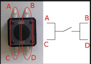
I noticed that the A-C and B-D pins are inherently connected, so that means I must either connect the wires from A and B, C and D, or A-D or C-B. This makes sense as on the breadboard, the columns are always connected.
Next, an Arduino button wiring diagram inspired me to wire the circuit:
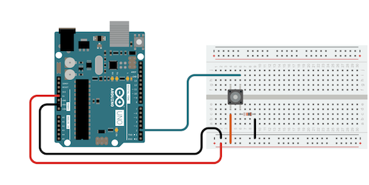
As you can see, the power and ground connections are connected to the horizontal pins (A-B or C-D according to the previous diagram).
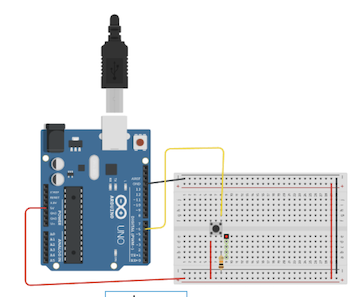
Mr Dubick then offered a similar diagram:
I used the following code:
/*
  Button

  Turns on and off a light emitting diode(LED) connected to digital pin 13,
  when pressing a pushbutton attached to pin 2.

  The circuit:
  - LED attached from pin 13 to ground through 220 ohm resistor
  - pushbutton attached to pin 2 from +5V
  - 10K resistor attached to pin 2 from ground

  - Note: on most Arduinos there is already an LED on the board
    attached to pin 13.

  created 2005
  by DojoDave <http://www.0j0.org>
  modified 30 Aug 2011
  by Tom Igoe

  This example code is in the public domain.

  https://www.arduino.cc/en/Tutorial/BuiltInExamples/Button
*/

// constants won't change. They're used here to set pin numbers:
const int buttonPin = 2;  // the number of the pushbutton pin
const int ledPin = 13;    // the number of the LED pin

// variables will change:
int buttonState = 0;  // variable for reading the pushbutton status

void setup() {
  // initialize the LED pin as an output:
  pinMode(ledPin, OUTPUT);
  // initialize the pushbutton pin as an input:
  pinMode(buttonPin, INPUT);
}

void loop() {
  // read the state of the pushbutton value:
  buttonState = digitalRead(buttonPin);

  // check if the pushbutton is pressed. If it is, the buttonState is HIGH:
  if (buttonState == HIGH) {
    // turn LED on:
    digitalWrite(ledPin, HIGH);
  } else {
    // turn LED off:
    digitalWrite(ledPin, LOW);
  }
}
Then, the code worked, I didn’t include a video, here as I think it is more clear shown on the RP 2040 Pi Pico.
Using a distance sonar sensor
I felt that implementing a distance sonar sensor with an LED such that the LED would light up under a specific distance as monitored by the sensor would be pretty easy. The Arduino Uno is extremely versatile in that it has an entire collection of different, as shown in the pinouts/data sheet section below.
This website was very useful in explaining the wiring setup for the distance sensor. And this website was useful in explaining the functionality of the sensor as well as the code.
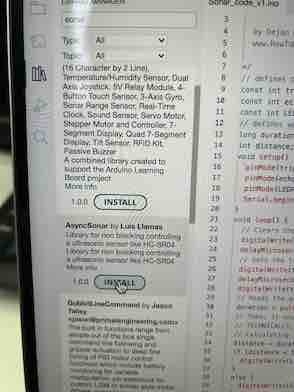
I also installed this library:
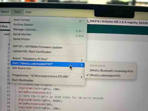
The port selection on the Arduino is very different than that on a windows computer:
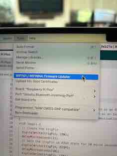
This is an example of a firmware update on mac:
Below is the code that I found on this website:
/*
  Ultrasonic Sensor HC-SR04 and Arduino Tutorial

  by Dejan Nedelkovski,
  www.HowToMechatronics.com

*/
// defines pins numbers
const int trigPin = 4;
const int echoPin = 8;
// defines variables
long duration;
int distance;
void setup() {
  pinMode(trigPin, OUTPUT); // Sets the trigPin as an Output
  pinMode(echoPin, INPUT); // Sets the echoPin as an Input
  Serial.begin(9600); // Starts the serial communication
}
void loop() {
  // Clears the trigPin
  digitalWrite(trigPin, LOW);
  delayMicroseconds(2);
  // Sets the trigPin on HIGH state for 10 micro seconds
  digitalWrite(trigPin, HIGH);
  delayMicroseconds(10);
  digitalWrite(trigPin, LOW);
  // Reads the echoPin, returns the sound wave travel time in microseconds
  duration = pulseIn(echoPin, HIGH);
  // Calculating the distance
  distance = duration * 0.034 / 2;
  // Prints the distance on the Serial Monitor
  Serial.print("Distance: ");
  Serial.println(distance);
  delay(1000);
}
I modified the code above so that when a certain distance is reached, an LED lights up. The LED is set to a digital pin that controls its HIGH and LOW states:
/*
  Ultrasonic Sensor HC-SR04 and Arduino Tutorial

  by Dejan Nedelkovski,
  www.HowToMechatronics.com

*/
// defines pins numbers
const int trigPin = 4;
const int echoPin = 8;
const int LED_PIN = 13;
// defines variables
long duration;
int distance;
void setup() {
  pinMode(trigPin, OUTPUT); // Sets the trigPin as an Output
  pinMode(echoPin, INPUT); // Sets the echoPin as an Input
  pinMode(13, OUTPUT);
  Serial.begin(9600); // Starts the serial communication
}
void loop() {
  // Clears the trigPin
  digitalWrite(trigPin, LOW);
  delayMicroseconds(2);
  // Sets the trigPin on HIGH state for 10 micro seconds
  digitalWrite(trigPin, HIGH);
  delayMicroseconds(10);
  digitalWrite(trigPin, LOW);
  // Reads the echoPin, returns the sound wave travel time in microseconds
  duration = pulseIn(echoPin, HIGH);
  // Calculating the distance
  distance = duration * 0.034 / 2;
  // Prints the distance on the Serial Monitor
  Serial.print("Distance: ");
  Serial.println(distance);

  if (distance <= 20){
    digitalWrite(13, HIGH);
  }

  else {
    digitalWrite (13, LOW);
  }

  delay(1000);
}
I then implemented a simple if-then-else statement to determine if the LED should light up or not.
This was the final result:
Data Sheet
This is the pinouts for the Arduino Uno:
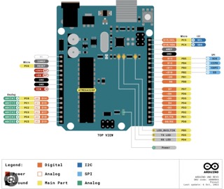
Here is the official data sheet
Analysis:
- The Arduino Uno is extremely versatile and offers a variety of different output pins.
- There is inputs and outputs, TX/RX, as well as SCL/SDA communication buses.
- Has interface for programming and serial communication.
- It operates at a clock frequency of 16 MHz.
- Storing temperature range: -40˚C to 85˚C
- Pins D0 to D9 are the same configuration for both Digital and GPIO labels.
This is the power tree for the Arduino Uno:
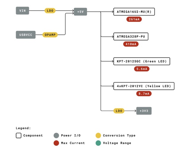
This is essentially the distribution of current and voltage within the Arduino Uno.