Designing the Board
Since my final project is a tennis ball machine, I decided to see if I can create a controller system for the motor that launches the tennis balls. The motor’s speed determines the speed of the tennis balls, so my plan is to let a potentiometer control the speed of the motor.
This way, the motor’s speed could be adjusted.
Voltage regulation
A DC motor draw a lot of current, more than an Arduino, a Raspberry Pi Pico, or Seeeduino board could support, so a mosfet, motor shield, or some kind of current regulator in the circuit. Note that the current drawn is not forced into the motor, but rather the motor draws the amount it needs to power whatever it is powering.
I used the L298 motor shield as my current regulator.
Small Motor
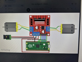
Using the schametic from Merritt Backerman, I built the circuit using the motor shield:
 .
.
This is my wiring with jumper wires and a breadboard:
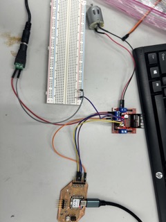
The power supply is needed to power the motor, due to the fact that neither the Arduino nor does my computer have the sufficient current or wattage to drive the motor.
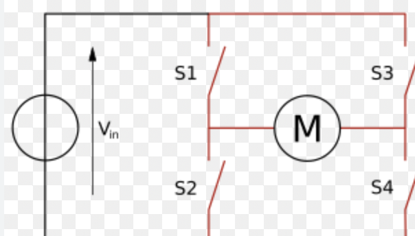
Additionally, I also watched this video that helped me understand the basics of an H-bridge and how to integrate it using the Arduino.
In essence, an H-bridge is an electronic circuit that switches the polarity of a voltage applied to a load:
These are the videos that demonstrate the workings of the small 5 volt motor:
Tetrix motor
The original decision for the inclusion of the Tetrix motor in my final project was to give the tennis machine a lot of torque, which is abundantly present in the Tetrix motor, at 320 oz in and 152 max rpm.
Then, I would include a gear box, in order to speed up the gear attached to the Tetrix motor. However, as you will see in my week 13, molding and casting, that idea was not my best.
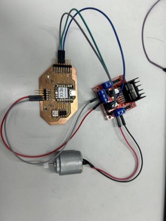
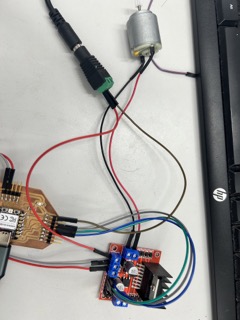
So, I moved on to the Tetrix motor, using the same wiring and code, which is presented below:
int enA = 7;
int in1 = 5;
int in2 = 4;

void setup() {
  // put your setup code here, to run once:

pinMode(enA, OUTPUT);
pinMode(in1, OUTPUT);
pinMode(in2, OUTPUT);
Serial.begin(9600);
}


void demoOne(){
  // This will run the motor in both directions at a fixed speed.

  digitalWrite(in1, HIGH);
  digitalWrite(in2, LOW); // initiation, and spinning it clockwise
  analogWrite(enA, 200);

  delay(2000);

 digitalWrite(in1, LOW);
  digitalWrite(in2, HIGH); // turn it the other way.
  delay(2000);
  digitalWrite(in1, LOW);
  digitalWrite(in2, LOW);
}

void demoTwo(){
  digitalWrite(in1, HIGH);
  digitalWrite(in2, LOW);

  for (int i = 0; i < 256; i++){
    analogWrite(enA, i);
    delay(20);
  }

  for (int i = 255; i>= 0; --i){
    analogWrite(enA, i);
    delay(20);
  }
  digitalWrite(in1, LOW);
  digitalWrite(in2, LOW);
}


void loop() {
  // put your main code here, to run repeatedly:
demoOne();
delay(1000);
demoTwo();
delay(1000);
}
Note that this code was simply a demo of the motor. It does not represent the motor actually working in conjunction with a potentiometer. That code will be included below.
H-bridge Pinout and Description
This is the L298n H-bridge pinout:
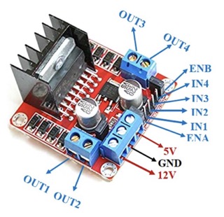
The H-bridge has a 5 volt logic input, which is the voltage used to control the logic. It also has an Enable pin, and 2 other direction control pins. The Enable pin controls the speed of the motor through an digital process called PWM, which is a process of controlling the motor speed by changing the width of pulses sent to the H-bridge “enable” input. By varying the pulses, this process ensures that the motor is not spinning all the time, but only part of the time in a rhythmic fashion.
Even though PWM pulses are not true analog signals, you have to call it using analogWrite() in the Arduino IDE.
The L298 H-bridge also has a voltage input for the power supply, and a power and a ground for the motor itself.
Tetrix motor
I felt ready to switch to the 12 volt tetrix motor, and changed my power supply to a 12 volt 5 amp one. Using the same schamtic as before, I made the circuit work.
This is a typical Tetrix motor used in Robotics:
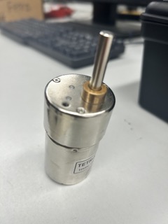
This is the tetrix motor hooked up to a dc power supply:
Potentiometer
In order to make the motor adjustable, I added a potentiometer. Here is its inner structure:
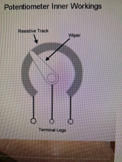
The middle leg is the data line, and the controllable one. I used an analog pin on my Seeeduino XIAO and integrated the potentiometer into my circuit.
The following code was used in conjunction with the potentiometer, which controlled the speed of the motor:
int enA = 26;
int in1 = 27;
int in2 = 28;


int SpeedControl1 = 29;


// Motor Speed Values - Start at zero


int MotorSpeed1 = 0;


void setup() {
 // put your setup code here, to run once:


pinMode(enA, OUTPUT);
pinMode(in1, OUTPUT);
pinMode(in2, OUTPUT);


}

void loop() {


 digitalWrite(in1, HIGH);
 digitalWrite(in2, LOW);


 MotorSpeed1 = analogRead(SpeedControl1); // AnalogRead reads the values of the input from the potentiometer and see what the number is from 0 to 1023.

 MotorSpeed1 = map(MotorSpeed1, 0, 1023, 0, 255); // Then, we set the MotorSpeed to the analog input and map it.

 if(MotorSpeed1 < 10) MotorSpeed1 = 0;

 analogWrite(enA, MotorSpeed1); // Finally, we set the enA pin to the motorspeed obtained before.

}
This video shows the wiring and working condition of the motor with a potentiometer:
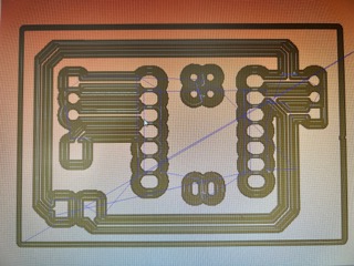
KiCAD
Next, I milled out my board by first designing the schematics in KiCAD:
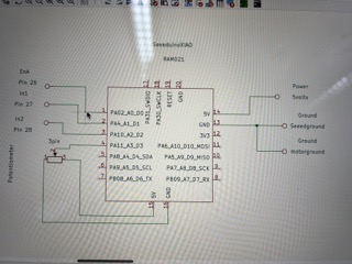
However, I noticed that the schematic was a bit convoluted and inefficient. It also did not look asthetic. Then, Dylan Ferro suggested that I use a different type of connector schematics and footprints:
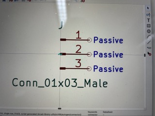
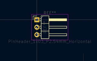
Here is my final design in KiCAD:
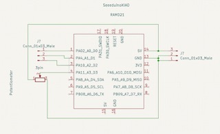
I exported the KiCAD design into the school engineering google drive folder, and then into Bantam. This process is the exact same as week 6 and 8’s process. Once again, I only selected Front Copper and Edge cuts in the list of work areas.
Milling the Board
Then, I milled the board using the same technique as week 8.
From KiCAD, I exported the F.Cu and Edge.Cuts layers and uploaded them into the Bantam software, where the render is this:
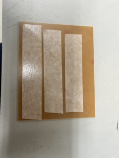
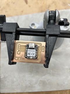
I put nitto tape on the backside of a copper board to hold it down:
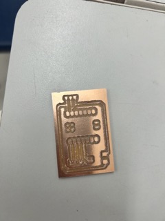
This was the finished result before deburring:
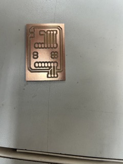
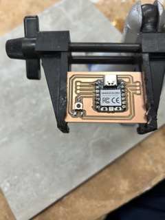
I used the side of another copper board to scrape away the excess debris in order to debur the board:
Then, I soldered the xiao and the potentiometer, which has 3 pads:
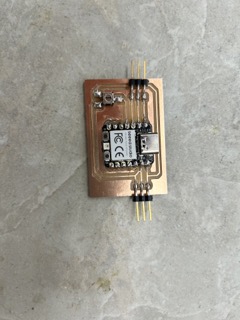
This was the completed soldering of the board, after the male header pins were soldered on:
After adding on the jumper wires and the motor, here was the final result:
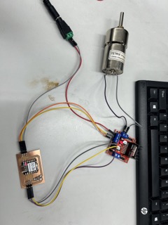
This is the circuit working. Note that I controlled the potentiometer with a screwdriver: