Project Design
Project Idea
We have to make something creative using the CNC machine (aka Shopbot). I wanted to make a shelf using the Shopbot. The plan is that I will cut out multiple boards and interconnect them together at the end through the use of dog bone joints. At first, I wanted to make an optical illusion shelf that twists itself or a hexagonal shelf that looked very neat. I took some inspiration from here.
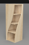
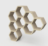
However, fellow student Dylan Ferro told me that this won’t be very realistic because the hexagon requires 3 concurrent joints connected to each other at the same place. The geometry of the design is extremely complex, especially when I must connect them together without glue or any other auxiliary tools.
For the optical illusion design, there will still be many joints connected to the each other, especially near the top fo the long wooden piece, where the structure is very thin.
So, I thought of making a more simplistic shelf like this:
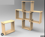
I went to Fusion 360 and started to work with designing the shelf.
Fusion 360 Design
2D sketch
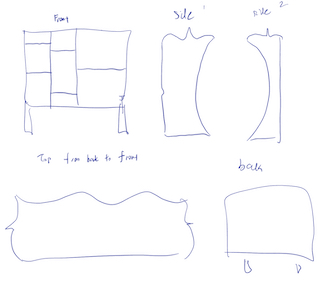
First, I decided to make curved surfaces for the back, front, sides, but keep the central boards flat and perpendicular to to the sides.
Before designing in the software, I decided to make a simple drawing in Notability:
At first, I thought that my shelf was too complicated, so I decided to scale it down a little. I looked at last year’s Fab Academy students and take some inspiration from them.
- Taking inspiration from Barbara Morrow, I reconsidered designing my shelf to a simpler version.
Constructing the pieces
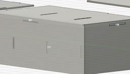
First, I made a 3D rendition of the entire shelf:
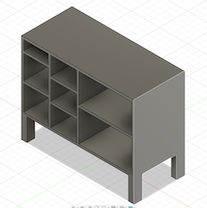
The process of actually making this shelf wasn’t hard, as it mostly consisted of just rectangles.
To make the shelf, I started with the back wall, and drew rectangles on it. Then, I extruded those thin rectangles to make the individual panels of the shelf. Finally, I just added the legs at the bottom.
However, I realized that even this design was too complicated because I needed to cut out and put together at least 20 different pieces of wooden boards.
So, I decided to scale down the complexity even further by just keeping the left most column of the shelf.
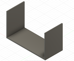
Note that this picture only details the basic structure of the shelf.
2D Rendition
Before I started, I made sure to keep every dimension as parametric as possible.
Back Wall
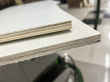
Note that I am going to cut out my shelf’s pieces on 1/2 inch plywood, so one of my user parameters is 0.5’’ for the wood width.
First, I made the 2D sketch of the back wall:
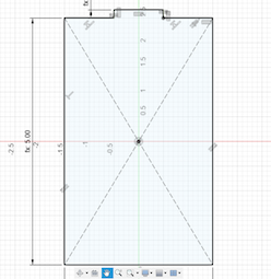
I constructed a tab on all 4 sides, to be put into the holes that I will later create.
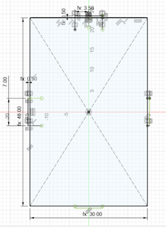
The above picture shows the right dimensions.
Later, I also created 2 holes in the center, 16 inches down from the top and bottom so that the 2 shelves divide the back wall into thirds (48 inches in length) spaced apart from each other. These holes are offsetted too, length by 0.1 inch and width by 0.05 inch so that the wood has space to fit itself into it (kerf).
Top/Bottom Boards
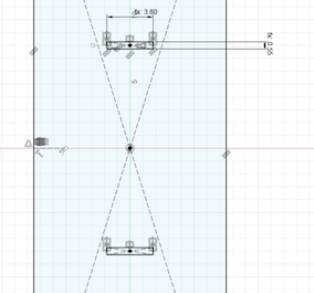
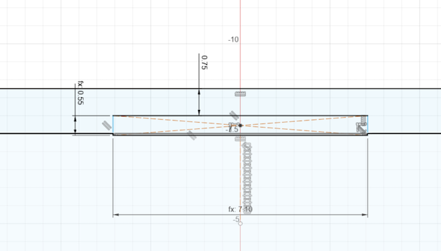
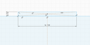
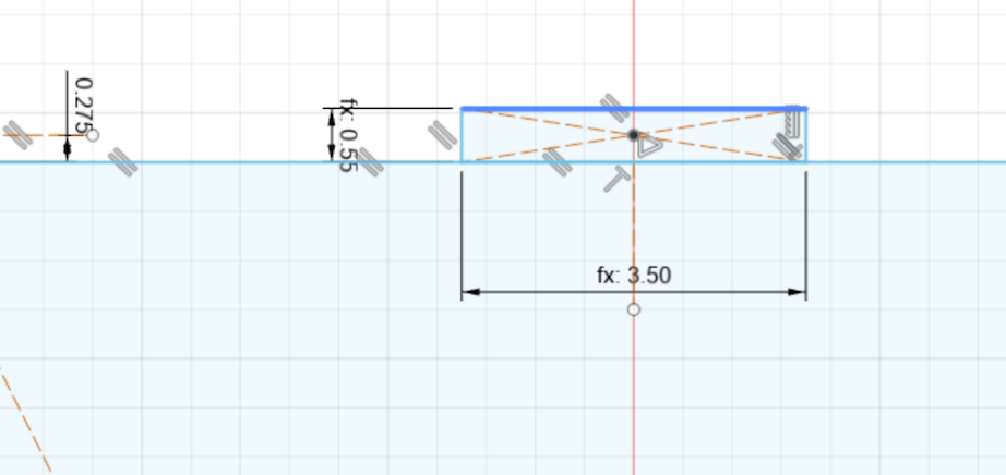
Next is the top/bottom boards. Since they are attached to the back wall, I put a rectangular hole on each board. These holes added 1.25 inches to the length of each board. I also made notches on the sides of the top/bottom boards in order to be put into the side boards.
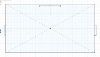
Note that I kept the lengths of the notches and holes consistent. It is either 7 inches long or 3.5 inches long, depending on the size of the board that it is on.
Side Boards
Next were the side boards. First, I had to make 2 holes in the middle (offsetted like the back wall) and then make additional holes on 3 more sides, for the back wall, and the top and bottom boards:
Top hole of side board:
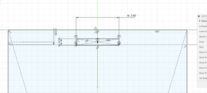
Middle hole:
Longways hole:
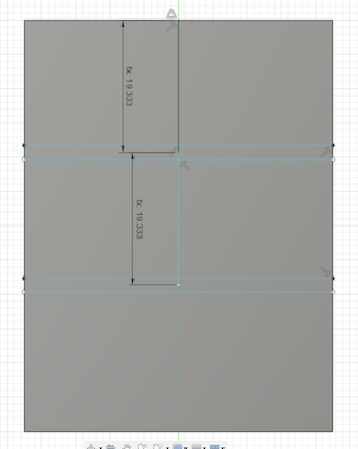
Note that the shelf is divided into thirds by the individual panels. So, I had to reflect that in my design by carefully measuring the distance between the two holes on the back wall and mirroring that distance to make the two holes on the side boards, using the same distance.
Shelf boards
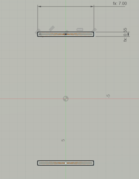
Time to make the actual shelves. I make a notch on one end of them and another notch on each of their sides to fit into the back wall and side boards:
Shelf board back joint:
Notch:
Quick note
The design process for these 2D sketches is actually quite simple, as they are mainly rectangles and contain only straight lines. What makes it difficult is to make the sketchs fully constrained and making sure that the dimensions are correct.
I also heavily used the construction line and mirror features in order to make symmetric panels, notches, and holes.
Constraints
One problem I had with Fusion is my lack of understanding of constraints. Fortunately, ChatGPT helped me out with this part as it told me that the inspection tool could automatically identify missing constraints.
Luckily, I found a youtube video that told me exactly what to do. I just have to go to the text command and enter Sketch.ShowUnderconstrained. Next, I just had to apply the missing constraints to my sketches.
Joint testing and Result
After the 2D renditions are completed, I extruded each sketch by 0.5 in and here is the final result:
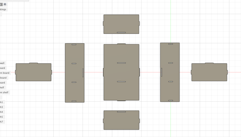
To test if it actually works, I first made every body in the design a component. Then, using the joint feature, I was able to “build” the shelf:
As you can see, the parts fit together well.
File Export
To export the design to Dr. Taylor and Mr. Dubick for approval, I had to export it as a .dxf file from Fusion 360.
Laser Cutting Test
I also tested the design using cardboard. I exported the Fusion files as a .dxf file into CorelDRAW and scaled the shelf down in a 1:3 ratio:
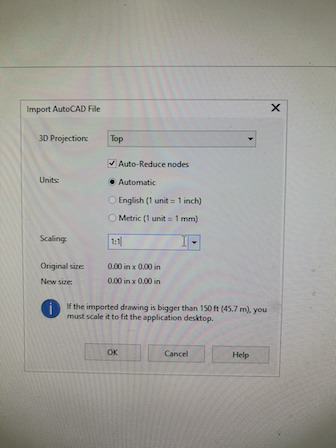
Then, I deleted the extra lines in the design and fitted all the sketches together (due to slight errors the form of overlapping).
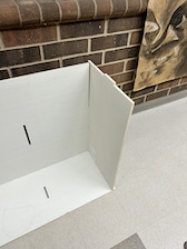
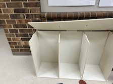
I used the laser cutter and produced a model shelf:
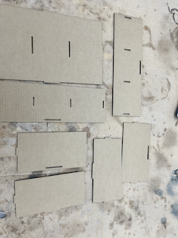
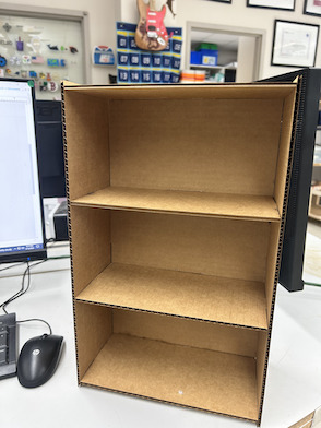
This proves that my design does work.
Thickness trouble
When Mr. Dubick measured the thickness of the 0.5 inch board I was going to cut on, the actual thickness was 0.476 inches. This meant that I needed to change my design.
Luckily, it was mostly parametric, so I didn’t have to completely redesign it.
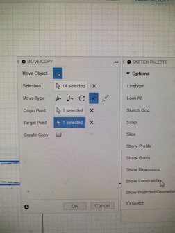
However, there were instances where I had to move faces/sketches to specific points. I struggled with this as my aim is not very good.
Following Garrett Nelson guidance, I used the point-to-point feature in Fusion 360 to quickly relocate sketches and faces:
Aspire
After Mr. Dubick and Dr. Taylor approved of my design, it was time to export it into Aspire.
Exporting files and tool path
I decided to export the .dxf files directly from CorelDRAW as the Fusion 360 files weren’t accurate. Inside the software, I combined the open vectors of the design to prevent errors:
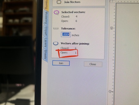
These are the files in Aspire:
Curve Trouble
Now, it is time to make the dog bone joints in Aspire. The dog bone joint is commonly used because of its simplicity and versatile nature. However, when I went to add a dog joint, I realized that I cannot. The cursor did not turn into a curve, which normally means that a dog bone joint is about to be applied:
This problem held me back awhile, but eventually I figured that there were millions of nodes in my file:
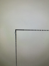
Each black dot represents a single node.
With this many nodes, it was impossible for Aspire to know where the corner is.
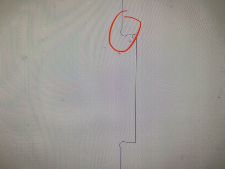
So, I started to delete the nodes by highlighting a section and deleting the them.
Later, I discovered that I can just use the convert nodes to curves tool:
However, this still failed to do the job, and I still could not apply a dog bone joint to the edges in my design file.
Dog Bone Joint
Finally, I discovered that if I imported my sketches directly from Fusion 360 to Aspire, the nodes won’t be scattered everywhere throughout the file.
Under the joints window, I selected dog bone joints as the joint type and applied it to every corner in each cutout piece (the rectangular holes).
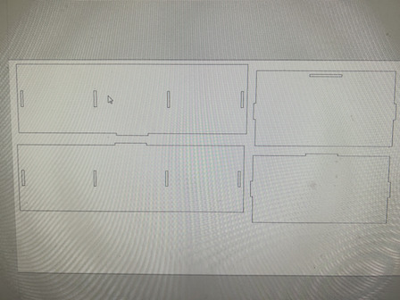
Now, my file looks like this:
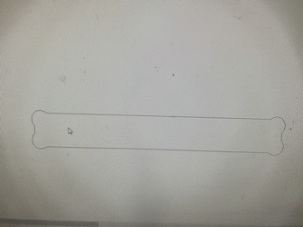
Notice that the dog bone fillets are applied to every inward facing corner
Size Trouble
Unfortunately, as I was making the design, I did not take into account the fact that each person only gets to have a 96 by 48 inch piece of plywood to cut on. As a result, I made my design too large to fit, and I ended up using the ShopBot twice to cut my design.
Shopbot Cut - Part 1
Setup and aircut
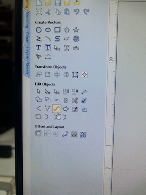
In order to finalize the Aspire file, I had to create a tool path, which are listed in this tab:
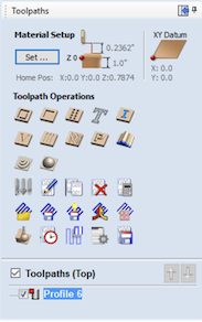
I used the profile and pocket tool paths, which are represented by the first two symbols in the above image. According to ChatGPT, the profile tool path follows the outline of a shape or boundary, cutting out the material to create the desired shape. And a pocket tool path removes material from the inside of a closed shape.
As such, I used the profile tool path on the large, overall design of the pieces, and I used the pocket tool path in order to remove the rectangular holes within the boards.
Here are the complete tool paths:
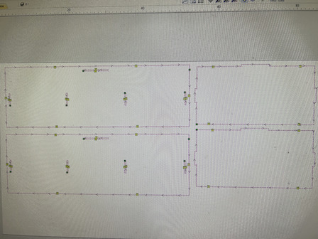
Notice that there are also green squares within the tool path. These are called “tabs”, and they are a small part of the path intentionally left uncut by the ShopBot, so that the entire piece do not accidentally become airborne (the spinning bit has the power to rip the board off the table).
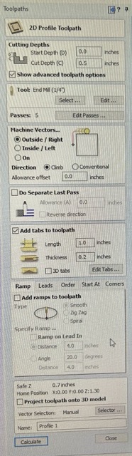
Here is how I adjusted the settings for the tool bit:
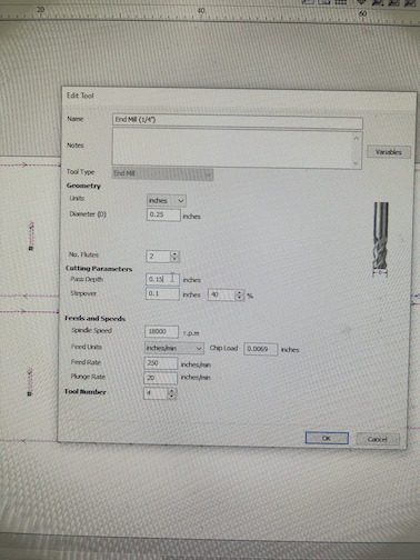
It is a quarter inch milling bit, and it is going to cut 0.15 inches of the material in terms of depth with every pass.
After generating the tool paths, I saved the files (separately for the profile and pocket tool paths).
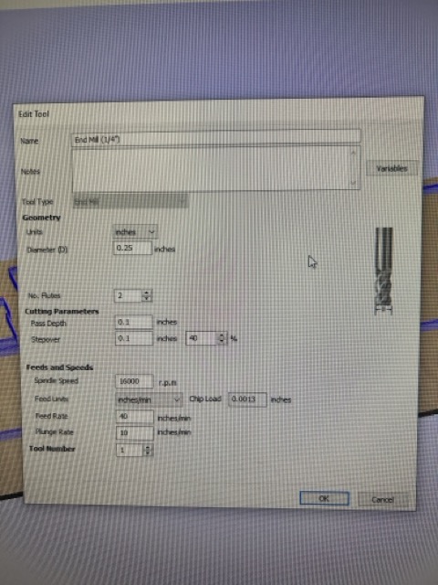
Final toolpaths:
These images show the final toolpaths and the various settings that I created:
Shopbot Settings
To operate the ShopBot, I essentially followed the workflow described at the end of this page.
The wood has to be aigned with the origin of the bed along the corner and secured with plastic nails.
This is the control panel for the Shopbot:
Here is where you can jog the axis of the Shopbot and home it if needed.
To home the Shopbot, one has to remember to set the X and Y axes to 0 and make sure that the Z axis is homed according to the bed of the Shopbot, NOT the surface on top of the material.
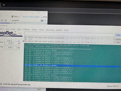
In this control panel, I also uploaded the tool paths that I saved.
After uploading the files, I ran a test cut to see if it will work. Then, I cut out my pieces.
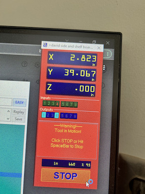
This is the position tab where the coordinates of the Shopbot bit is reported everyone tenths of a second.
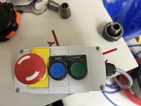
These are the emergency, reset, and start buttons for the Shopbot.
Results
Here is a shot of the Shopbot and the bit that cut out the wood pieces:
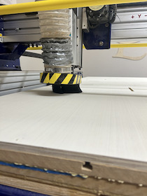
As seen in the picture, the piece of wood that I was cutting is secured onto the bed, and the you can see how the axis are labeled in the upper right corner.
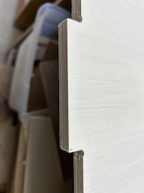
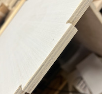
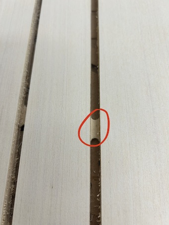
The dog bone joint hole and notches turned out good:
These were the pieces left intentionally uncut (tabs) that I described earlier:
After the cut, I used a hammer and a chisel to cut out the tabs, I also detached the wooden board from the bed by removing the plastic nails.
Sanding - Part 1
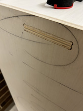
In order to get a more complete finish and so that I don’t get splinters, I sanded the pieces that I cut. This is what the wood looked like before sanding:
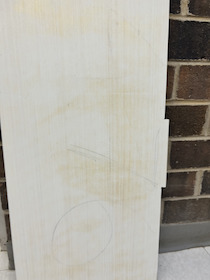
I used an electric 120 grit sander to sand down the wood. However, I pressed the sander to the wood for too long, and the wood was burnt:
So, in order to avoid that, I switched to a lower grit at 80, and had no trouble doing rest of the boards. After sanding, I was able to git the dog bone joints together nicely:
Shopbot Cut - Part 2
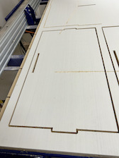
Using the same process as part 1, I cut out the remaining 3 pieces of my shelf. However, I made the mistake of not putting my design as close to the origin as possible:
I will make sure to avoid this mistake to conserve space in the future.
Gradient Trouble
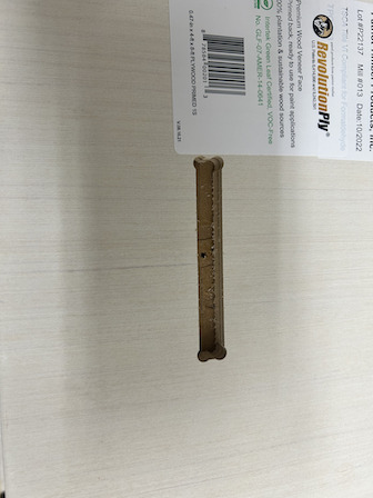
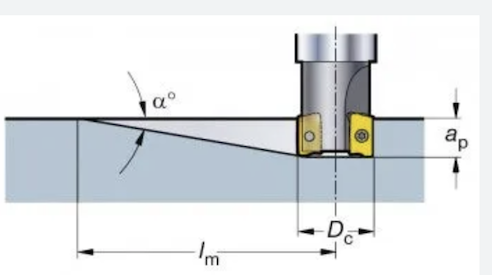
There was, however, a much larger problem with the cut itself. Somehow, the settings of the Shopbot was not well-adjusted. Normally, when the machine begins its cut, the bit starts spinning and it cuts the wood. The bit would cut the wood starting from the wood’s surface, and then moving downwards as it goes forward. This process is called ramping:
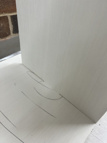
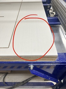
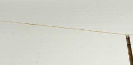
However, my cut did not work like this. The bit started to ramp before it even got to the start of my design. But, it lifts itself upwards and downwards intermittently, leaving behind scars on the woods surface:
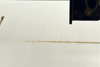
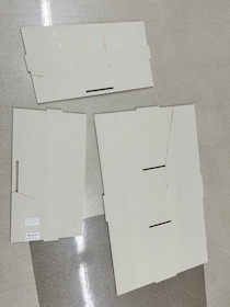
Anyhow, the last 3 pieces still turned out well in the end:
Sanding - Part 2
When I sanded the boards this time, I made sure that I didn’t over-sand them.
Final Construction
Now, it is time to construct the shelf from the boards. Originally, I put the top/bottom boards and the shelf boards in the side board first:
But then, I found that it wasn’t possible for me to fit the back wall into everything else, as the parts refused to connect.
So, I went a different way, but first attaching the side, back, and top boards together to form a triple joint:
There were some notches that were a bit too big to fit in the holes, so I sanded them down a little.
From Mr. Budzichowski’s and Mr. Dubick’s help, I was eventually able to get every joint in, although sometimes we had to hammer them in:
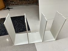
This is the completed shelf (with added reinforcements):
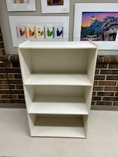
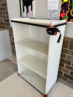
I also made sure to hide the scars when I was constructing the shelf.
ShopBot workflow
Below is the workflow for using the CNC machine in our lab:
1. Shopbot Machine Setup
- Find a teacher or partner to work with you when you operate the Shopbot.
- Check to see that the machine has been warmed up. Ask a teacher.
- Measure the thickness of the material that you plan to cut.
- Put on eye and ear protection.
- Close the doors.
- Check to see bit is not loose.
- Start ShopBot Command Console
- Raise the Z-axis so the bit won’t drag on the table (no higher than 4 inches)
- Use the proximity switch to set Calibrate X & Y AXISES. (C3 keyboard command)
- Move the tool to over the board (J2 18,24)
- Calibrate Z AXIS on the table. (C2 keyboard command)
- Raise Z AXIS 3 inches using the JZ 3 command
- With your instructor, attach material to the table.
- Raise Z AXIS 3 inches using the JZ 3 command
- Set new X and Y Origins for your design
- Raise the Z-axis so the bit won’t drag on the table
- Using keyboard jog to the appropriate X and Y location. (J2 X,Y)
- Using keyboard to zero the appropriate X and Y Location. (Z2)
- You set origin.
- Select Cut
2. Start up Aspire and VCarve software
- Open your file
- Select objects you wish to cut
- Select Toolpath
- Pin Toolpath
3. Click on material setup
- Check Z - zero is on the bed, NOT the board
- Enter the thickness of the material *
- Model position material should be the same thickness as the material.
- Click OK.
4. Go to TOOL PATH OPERATIONS
- Select 2D Profile Toolpath
- Under cutting depth, select the cut depth of the material (CLS tools).
- Select the proper tool -CLS down bit ¼
- Click add tabs and add tabs
- Hit CALCULATE.
- Preview toolpath
- Click on CLOSE
- Select SAVE TOOL PATH and save the file in a shopbot format
5. Conduct air cut
- Select FILE-LOAD
- Load the appropriate file
- We Select 1 3-D offset
- Press ENTER
- Turn on the spindle by pressing the big GREEN Button
- You should hear a “SOUND” of the spindle now turning
- Press ok
- After checking that everything is good; press space bar
- Select quit
- Return to origin (J2 0,0)
6. Perform cut
- Select FILE-LOAD
- Load the appropriate file
- Select no offset rather than 1 3-D offset
- Press enter
- Turn on the spindle by pressing the GREEN Button
- You should hear a “SOUND”
- Turn on the vacuum
- Press enter again to start cut
7. Cut is done
- Turn off vacuum (which is so loud you shouldn’t forget)
- Use a hammer and chisel to remove tabs
8. Clean up after yourself
- Get a broom and sweep