Designing and Molding
In order so that my design could be aligned with my final project, I decided to conduct a proof of concept where I will mold out the flat cylinders that shoot out the tennis ball. In this scenario, I will make scaled down versions of the actual wheels, and put them on a track, each with a low-torque 5 volt motor (the tetrix motor is unpractical as it spins too slowly). The ball I will be using is a rubber ball.
I don’t think I will be getting the whole mini-structure of my machine working this week, so I will mainly document the molding process of the wheels, and I will talk about the remainder later in my final project section.
Design process
When I thought about making a mold, I first went with subtractive design where I subtract one design from another. When I conferred with Mr. Dubick, he said that it is best to use the push and pull extrusion feature in Fusion 360. The idea is that I take the profile of a design and extrude it downwards into a rectangular block.
First, I decided to build gear ratios with the lego box and 3D print attachments to the gears that fit with the Tetrix motor.
I went to this youtube video that was really helpful in understanding a gearbox.
Following the visual in the video:
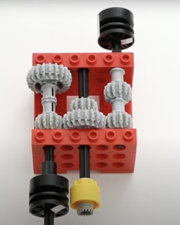
I made my own lego gearbox. Later, I plan to buy metallic motors that have more defined edges and are stronger than the lego pieces.
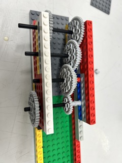
Notice that the gearbox contains gears with smaller teeth interlocking their teeth with larger gears. Although this decreases the torque, it increases the speed of the gear. This is an inverse relationship.
Through my calculations, the first gear rotates about ⅕ for every time I spin the last gear. This means that when the Tetrix motor spins at 100 rpm, the last one will spin around 400-500 rpm. However, this also means that the last gear will have ¼-⅕ less torque.
Time to design the connector for the motor. This will have the joint for the tetrix motor on one end and a connector for the lego axle on the other.
When it was printed out however:
I noticed that it was too loose when fitted with the tetrix motor’s shaft. As a result, I have to reduce the offset from the tetrix motor’s dimensions by 0.2mm on both sides.
Here is the current video for the tetrix motor turning the gears:
There was one problem, however. I noticed that the torque was way too low. With the slightest tap on the end motor, the tetrix motor would buckle under the torque pressure and it would stop spinning completely and start to turn itself.
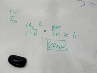
According to its data sheet, the tetrix motor has 700 oz -in of torque, which translates to around 43.75 pounds. The smaller gears in the gear box have 17 teeth, while the larger one has 40. Since there are 5 levels of gears (I added another one), there are 4 reductions in torque, resulting in:

pound inch of torque.
This is clearly far from enough. My calculations could be off given that I probably used less than a pound of force with my finger and stopped the motor.
Further considerations
I see 2 options ahead of me:
The first is to buy an extremely high torque tetrix motor and adapt it into the lego gear box to make the model. The second is to straight up by a high torque, high speed regular 12 volt DC motor that eliminates the use of the gear box.
After asking ChatGPT, it tells me the options for each one:
| High torque tetrix motor alternatives | High torque + high speed DC motor |
|---|---|
| AndyMark NeveRest Motors Torque = 8.75 oz in | Faulhaber DC motor Torque = 2.688 oz in |
| REV Robotics HD Hex Motor Torque ≈ 600 oz in |
I realized that the torques of these motors are still too small. The Falhaber motor has a top speed of 11000 rpm. I only needed the ball machine to spin at around 1000 rpm. So its torque would be increased to around 30 oz in, or less than 2 pounds, definitely not enough.
After a bit of searching, I found this motor from an official tennis ball machine replacement store. Although there is no official product description, I think it is worth a shot. After checking in with my parents, my dad (who has a degree in Industrial Automation) told me that since there was no official product description, it is not worth buying it. So I continued to look for a suitable motor on McMaster Carr.
After contacting the company via phone number, I was able to find 2 OK motors: the square face motor at 4200 rpm and 40 in-oz, and the brush motor at 3000 rpm and 21 in-oz.
When I discussed each option with my dad, we found that the torque is still too small.
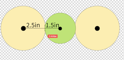
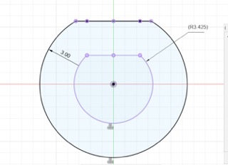
The above drawing shows my current plan. The wheels will be 5 inches in diameter, molded and made out of resin, with a coat of rubber around it. The tennis ball has a weight of 3 ounces, and a diameter of 3 inches approximately. So, the distance, R, from the center of the gear to the center of the tennis ball is around 4 inches, so in reality I would need to divided the torque of the motor by 4 in order to get the actual torque begin applied to the tennis ball.
After reviewing this video again, I realized that the motors they used are only 12 volt ones, and nothing more. So, I set out to find a motor with extreme speed, and I did find one. It is a RS550 motor. This data sheet shows that it has a torque of 551 g cm, which roughly translates to 7 in oz. However, its spin rate is 40000 RPM, meaning that if I made a gear box and changed that to 1000 RPM, I would get a resulting torque of 40 * 7 = 280 in oz of torque, which is around 17.5 lb in. (After a division of 4, resulting in a 4.25 pounds of force on the tennis ball).
This is far more than what I anticipated than the tetrix motor, leading me to believe that this design might actually work, it just requires the addition of a gear box, which I can either make or buy one.
However, after further consideration, I decided to abandon the gear box idea as it contains a lot of moving parts. The amount of parts that it has increases the chance of the motors breaking down. Also, it would be difficult to remove or add gears to the gear box in order to adjust for the correct torque. Overall, I thought it was cumbersome and tedious to use a gear box.
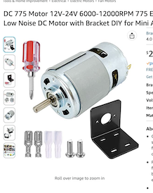
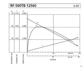
Then, I found this video documenting a working tennis ball machine. The motor they used was a 775 motor spinning at 7,000 RPM at 24 volts, and it seemed that it had enough power to rotate a plastic wheel at high speed and can shoot the ball for 60 to 70 feet. I found the motor on amazon:
Addiitonally, here is a graph that shows the torque vs speed of the motor:
I tested the motor using a power supply to measure the current of the motor:
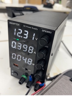
The maximum current spike was around 4 amps when I put my finger against the motor, and when it rapidly accelerates. Although it is able to maintain a stable current of 0.4 amps when running regularly. The fact that the spike is far above the H-bridge’s upper limit of 2 amps means I needed a motor shield that has a limit of 20 amps or more.
The torque of the new motor seems fine, as stopping it with the finger was impossible.
Designing the mold of the wheels
Next, it is time to design the wheels for the test version of my machine.
This is an online picture that I found for a replacement wheel of an actual tennis machine:
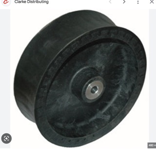
I planned to replicate this as best as possible. However, the curve of the cylinder would be harder to replicate, as it would likely require a spline, which could not be made parametric. (I wanted this to be parametric in order to make the process of redesigning the wheel easier).
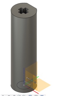
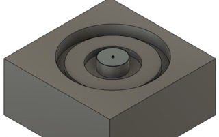
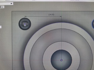
Here is the initial design of the wheel:
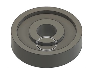
The dimensions are described below:
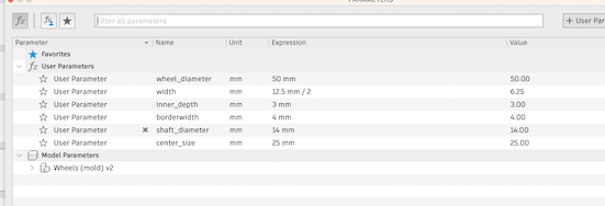
I soon realized that because the wheel is symmetric, the same design would have to be applied for the bottom of the wheel as well, which was impossible to do on a CNC milling machine. The bottom has to be flat and no part of it should be extruded upwards. This inverted shape creates a hollow volume beneath the wheel, which is physically impossible for the CNC machine as it cannot go under a material. So, I plan to copy and paste 4 of the same molds and glue 2 of each together, end to end.
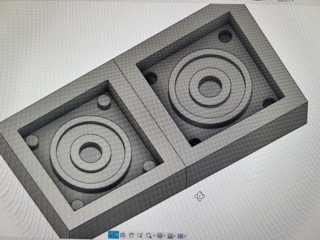
In order to make the mold, I first made a box (just large enough to cover the bottom) directly below the wheel. Then, I extruded each face by twice its height downwards into the box, forming a cut. For instance, the border of the wheels are 6.25 mm tall, so they are cut 6.25 mm into the box. Everything is essentially inverted in the mold.
Connector
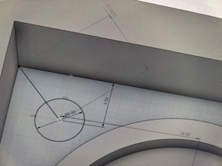
I also didn’t want the wheel to go on the lego connector directly, as that would be potentially unstable due to the small size of the lego axle. So, I made a connector instead, which is very similar to the connector between the tetrix motor and the axle.
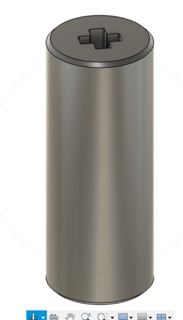
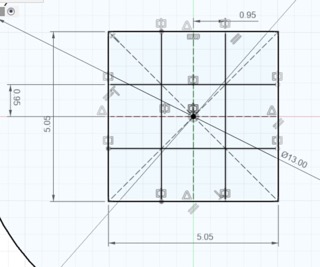
Notice that in this set of dimensions for the cross, I made every length larger by 0.05 mm due so that it can fit better into the lego.
Completing the Mold
In the middle of designing the mold, I was a bit confused as I was caught up in the whether to design in the inverse of a part, or its original shape. Then, I figured out that I am actually creating a mold of a mold… of a mold. So, first I am making a wax mold, then I will use silicone to make an inverse mold of the wax mold. Finally, I will use resin to make the final shape. Therefore, I should design the actual shape of the wheels, in their final form.
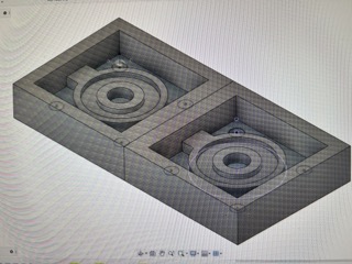
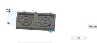
So, I made a copy of my mold, and joined it to the previous one, forming a rectangle:
As you can see in the image, I have also added 4 cylinders on the corners of each square, and I got this idea from Stuart Christhilf, a fellow Fab Academy student.
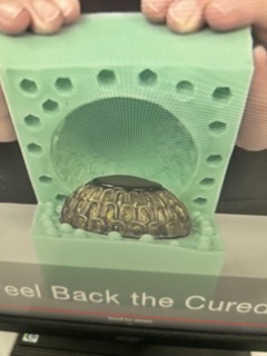
He also did a 2 part mold:
He put 4 holes in the corners and stuck a straw in the middle so that the resin could be pored in. The holes make the 2 silicone molds stick together.
Additionally, this online example of a silicone also shows the same thing:
I also did the same thing by adding small cylinders to 1 square of the model, and holes to the other. I generated a tool path with instructions provided by David Taylor, which is here.
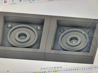
As the toolpath generated, I noticed that the cylinders weren’t the best choice:
The generated toolpath showed that the cylinders will still be joined to the walls, which is not what I wanted. So, I replaced them with spheres:
These are the dimensions for the spheres:
Here is the finished design model:
Then, I made joined the spheres to the walls with a bridge so that when the mold is filled with silicone, a rectangular hole can form. This hole will be used to pour the resin in:
There was a tiny face that I had to extrude to make the bridge complete:
Rendering
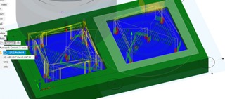
Using the previously mentioned Dr. Taylor’s instructions, I was able to generate the pocket path for the mold.
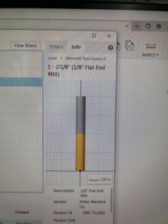
As a simplified explanation, I first created a new setup and defined the area in which to mill. Then, I selected the 2D pocket option from the dropdown menu and clicked OK, using the 1/8th inch flat end mill. This mill basically cleans out as much material as possible:
Then, another instructor named Garrett, who also completed Fab Academy and is an engineering instructor at Central Piedmont community college, helped me with the preferences. We set the tolerance setting to 0.01mm:

and also unchecked the box next to stock to leave:
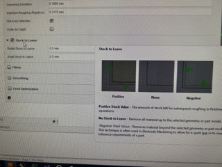
This is because I did not want any part of the mold to be left uncut.
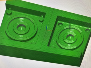
The rendered pockets are as follows:
This one is with the cylinders:
This one is with the spheres:
Fusion Update
For awhile, I did not double check the renderings, which turned out to be a mistake, because Fusion 360 received an update, which totally messed up my 2D pocket render.
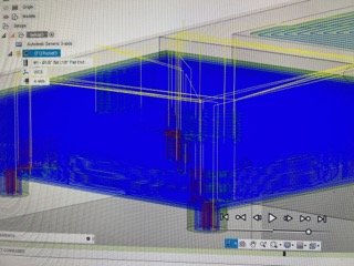
I asked Garrett again how to re-render my mold, he showed me the 3D adaptive feature under the 3D dropdown list, which is built to clear out as much material as possible in the shortest possible time. Again, I unchecked stock to leave and set the tolerance to 0.01mm. This is the new setup:
I also used the 1/16th inch flat end mill to get a higher accuracy.
One of the other requirements was to have a finishing the path, the purpose of this is to make the mold smoother.
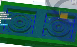
I generated this toolpath using the 3D parallel render, using a 1/16th inch ball end mill:
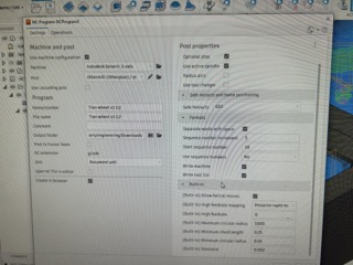
To export these files, I right clicked on each setup, and clicked “post”.
In the settings, I selected the Othermill machine, and the instructions were in .gcode format.
These are the final touches:
Creating the Wax
Unfortunately, my teacher Mr. Dubick did not have enough wax for me to perform the cut, as the cut was large, at 166 mm by 81 mm by 17.5 mm.
So, I took the remaining small pieces of wax and tried to melt them together using a heat gun. This didn’t go well, as I didn’t use a box to hold them. The melting point of wax is around 400 degrees Fahrenheit, and so I needed to make a box out of a material with a higher melting point.
I cut out 5 pieces of 3mm acrylic using the laser cutter:
However, acrylic is a very tough material, and so they were not completely cut through. I used a chisel to break the rest.
Then, I used clamps and sprayed Gorilla superglue to make the box:
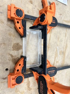
This is the finished box:
However, when I looked up acrylic’s melting point, I was surprised by the low temp. of 320 F˚. This was a mistake as I should have made sure all the parameters were correct before building the actual box.
After discarding the box, I built a ring using metal weights used in the laser cutter on top of a ceramic tile:
Then, I used the heat gun to mold them together:
It worked well at first, but I found out that the back was not even close to being done:
It was going to take a long time, so I just used one of the smaller pieces of wax instead, which was rectangular and also made out of 2 smaller rectangular wax blocks.
Unluckily, this meant that I had to rescale my design. I scaled it down by around 50%:
I had to repeat the rendering process and post machining process all over again.
Smoothing the wax
The wax wasn’t exactly flat, and so I had to perform a 2D face cut flatten it, using the 1/8 inch flat end mill.
In fusion, I created another setup using a box the same size as the wax, and exported the cut.
The steps to operate the wax machine was the same as the board milling machines, except that you had to manually enter the dimensions of the wax.
For reference, here is its user inteface:
When I imported the flat cut into Bantam, I got this preview:
I realized that it was because the origin was wrong. I went back into the setup and selected the right origin:
This time, the render was right:
The flat cut turned out fine:
Here is a video of the flat cut:
Wheel Mold
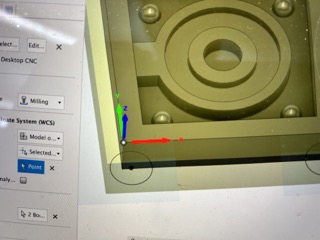
Now, I am ready for the actual molds. I deleted the flat cut file after it was placed over the molds in the preview:
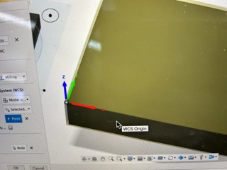
I selected the right origin:
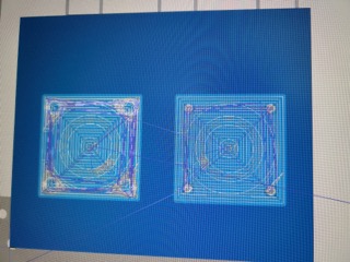
This is the render:
I also offsetted the z-axis by around 0.8mm, later changed to 2mm.
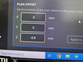
This is because the wax wasn’t exactly flat on the surface, so I had to dig beneath it a little.
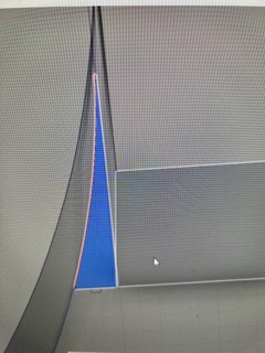
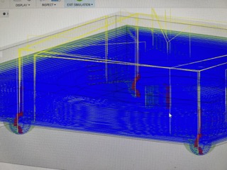
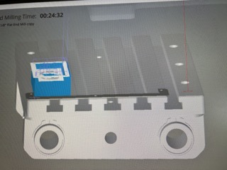
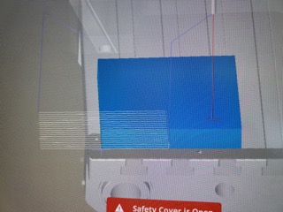
4 hours later, here is the roughing toolpath results:
As you can see, the mold was still very rough.
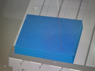
After the finishing toolpath, it was a lot better:
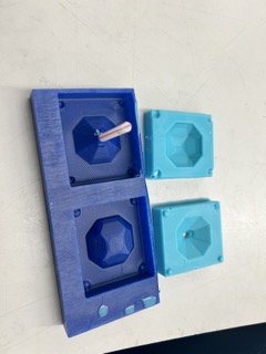
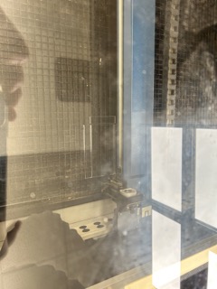
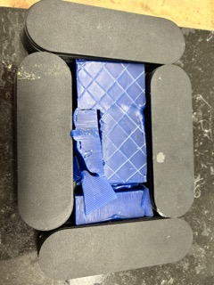
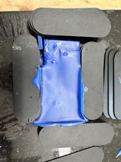
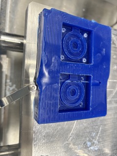
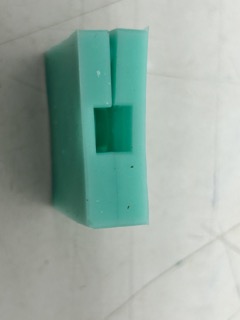
I used the Mold Star brand of blue silicone, mixing part A and B together with the same volume. I then poured it into the mold:
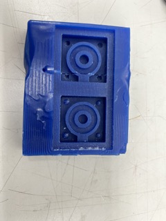
2 hours later, the silicone has fully solidified:
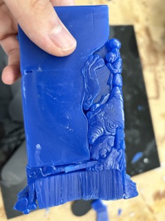
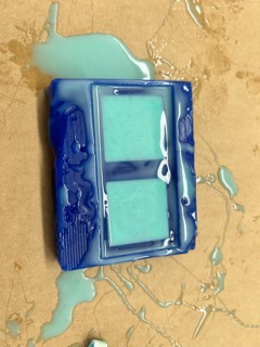
The spheres and rectangular hole came to use when I joined the 2 molds together:
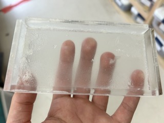
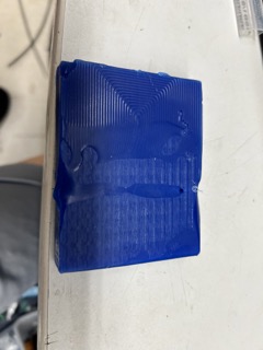
We ran out of resin, so I used a type of plastic, also using parts A and B.
I poured it into the little hole and let it sit for 10 minutes.
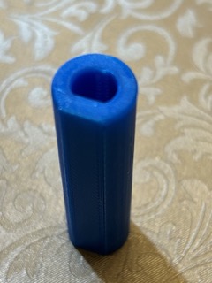
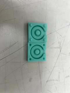
Here is the result:
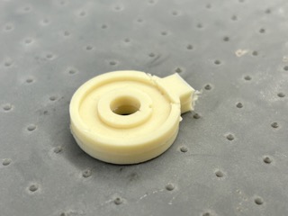
I sanded away the protrusion and the final product is below:
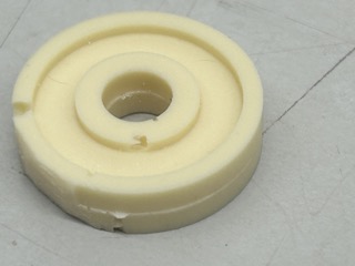
I noticed that the edges weren’t perfectly smooth, and my guess is that there were still bits of dust and debris left in the silicone mold.
Still yet, I haven’t noticed the embroidery machine getting caught by the bobbin until it was almost too late. Then, Harry Potter said, it is time for you to die, Mr. Sparky sparky boom boom man. And dead he was.