Accelerometer
Board cases
Over the last couple of weeks, I designed and milled 2 boards, the tetrix motor board and the LED board. In Fusion 360, I designed 2 simple boxes for the copper boards:
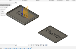
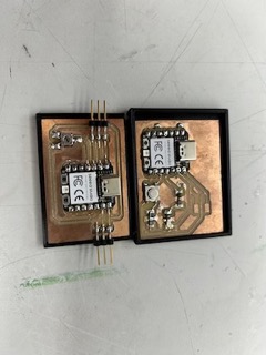
The final result after the 3d print was finished is as follows:
Accelerometer continued:
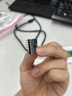
First, I soldered the the pins of the accelerometer to the board itself in order to work with the breadboard:
Next, I watched this tutorial on how to get the accelerometer working with the Raspberry Pi Pico, a microcontroller that I used back in week 4.
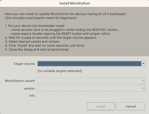
So, I booted up Thonny, and tried to connect the board to the software via USB. However, this failed to work as Thonny continuously failed to recognize the board. As a result, I asked Adam Stone for help. He explained that I would have to reinstall the micropython file for the RP2040 board every time when it doesn’t connect with Thonny.
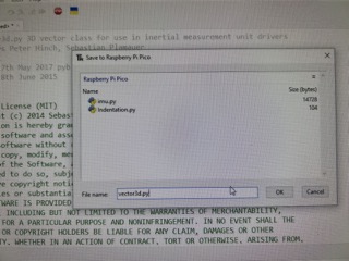
So, I did that, by selecting the target platform and the board name as seen below:
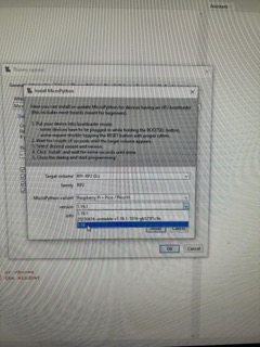
After that, it did connect to Thonny after I pressed the button on it to make it go to bootloader mode.
Next, following the video’s instructions, I uploaded the identifier code, which basically returns back the address (or the location of the memory) of the SDA and SCL connection pins on the I2C.
Then, I uploaded another code file that was very long and complex. According to the tutor in the video, it was supposed to activate the accelerometer and project the data in Thonny so that it shows you all of the accelerations in all 3 axis.
However, this didn’t work, and the error message is that Thonny couldn’t communicate with the accelerometer.
Then, I asked Mr. Dubick for help and he suggested me breaking the problem down.
First, I used a simple blink LED program on the RP2040 to make sure that the board itself works. Next, I used an Arduino to program the accelerometer, but it didn’t work.
So, I went to a new website that contained all the necessary information to get the accelerometer working with the Pico. I learned that SCL stands for serial clock and SDA stands for serial data. This website explained the inner workings of the component very well.
After I saved 2 libraries onto the board itself, I was able to get the temp. Sensor, gyroscope, and accelerometer to work perfectly. Note that the acceleration is written in g’s, where 1 = 9.8m/s^2
Here is the working code:
mcu_main.py
     from imu import MPU6050
    from time import sleep
    from machine import Pin, I2C

    i2c = I2C(0, sda=Pin(16), scl=Pin(17), freq=400000)
    imu = MPU6050(i2c)

    while True:
        ax=round(imu.accel.x,2)
        ay=round(imu.accel.y,2)
        az=round(imu.accel.z,2)
        gx=round(imu.gyro.x)
        gy=round(imu.gyro.y)
        gz=round(imu.gyro.z)
        tem=round(imu.temperature,2)

    print("ax",ax,"\t","ay",ay,"\t","az",az,"\t","gx",gx,"\t","gy",gy,"\t","gz",gz,"\t","Temperature",tem,"        ",end="\r")
        sleep(0.2)
imu.py
from utime import sleep_ms
from machine import I2C
from vector3d import Vector3d


class MPUException(OSError):
    '''
    Exception for MPU devices
    '''
    pass


def bytes_toint(msb, lsb):
    '''
    Convert two bytes to signed integer (big endian)
    for little endian reverse msb, lsb arguments
    Can be used in an interrupt handler
    '''
    if not msb & 0x80:
        return msb << 8 | lsb  # +ve
    return - (((msb ^ 255) << 8) | (lsb ^ 255) + 1)


class MPU6050(object):
    '''
    Module for InvenSense IMUs. Base class implements MPU6050 6DOF sensor, with
    features common to MPU9150 and MPU9250 9DOF sensors.
    '''

    _I2Cerror = "I2C failure when communicating with IMU"
    _mpu_addr = (104, 105)  # addresses of MPU9150/MPU6050. There can be two devices
    _chip_id = 104

    def __init__(self, side_str, device_addr=None, transposition=(0, 1, 2), scaling=(1, 1, 1)):

        self._accel = Vector3d(transposition, scaling, self._accel_callback)
        self._gyro = Vector3d(transposition, scaling, self._gyro_callback)
        self.buf1 = bytearray(1)                # Pre-allocated buffers for reads: allows reads to
        self.buf2 = bytearray(2)                # be done in interrupt handlers
        self.buf3 = bytearray(3)
        self.buf6 = bytearray(6)

        sleep_ms(200)                           # Ensure PSU and device have settled
        if isinstance(side_str, str):           # Non-pyb targets may use other than X or Y
            self._mpu_i2c = I2C(side_str)
        elif hasattr(side_str, 'readfrom'):     # Soft or hard I2C instance. See issue #3097
            self._mpu_i2c = side_str
        else:
            raise ValueError("Invalid I2C instance")

        if device_addr is None:
            devices = set(self._mpu_i2c.scan())
            mpus = devices.intersection(set(self._mpu_addr))
            number_of_mpus = len(mpus)
            if number_of_mpus == 0:
                raise MPUException("No MPU's detected")
            elif number_of_mpus == 1:
                self.mpu_addr = mpus.pop()
            else:
                raise ValueError("Two MPU's detected: must specify a device address")
        else:
            if device_addr not in (0, 1):
                raise ValueError('Device address must be 0 or 1')
            self.mpu_addr = self._mpu_addr[device_addr]

        self.chip_id                     # Test communication by reading chip_id: throws exception on error
        # Can communicate with chip. Set it up.
        self.wake()                             # wake it up
        self.passthrough = True                 # Enable mag access from main I2C bus
        self.accel_range = 0                    # default to highest sensitivity
        self.gyro_range = 0                     # Likewise for gyro

    # read from device
    def _read(self, buf, memaddr, addr):        # addr = I2C device address, memaddr = memory location within the I2C device
        '''
        Read bytes to pre-allocated buffer Caller traps OSError.
        '''
        self._mpu_i2c.readfrom_mem_into(addr, memaddr, buf)

    # write to device
    def _write(self, data, memaddr, addr):
        '''
        Perform a memory write. Caller should trap OSError.
        '''
        self.buf1[0] = data
        self._mpu_i2c.writeto_mem(addr, memaddr, self.buf1)

    # wake
    def wake(self):
        '''
        Wakes the device.
        '''
        try:
            self._write(0x01, 0x6B, self.mpu_addr)  # Use best clock source
        except OSError:
            raise MPUException(self._I2Cerror)
        return 'awake'

    # mode
    def sleep(self):
        '''
        Sets the device to sleep mode.
        '''
        try:
            self._write(0x40, 0x6B, self.mpu_addr)
        except OSError:
            raise MPUException(self._I2Cerror)
        return 'asleep'

    # chip_id
    @property
    def chip_id(self):
        '''
        Returns Chip ID
        '''
        try:
            self._read(self.buf1, 0x75, self.mpu_addr)
        except OSError:
            raise MPUException(self._I2Cerror)
        chip_id = int(self.buf1[0])
        if chip_id != self._chip_id:
            raise ValueError('Bad chip ID retrieved: MPU communication failure')
        return chip_id

    @property
    def sensors(self):
        '''
        returns sensor objects accel, gyro
        '''
        return self._accel, self._gyro

    # get temperature
    @property
    def temperature(self):
        '''
        Returns the temperature in degree C.
        '''
        try:
            self._read(self.buf2, 0x41, self.mpu_addr)
        except OSError:
            raise MPUException(self._I2Cerror)
        return bytes_toint(self.buf2[0], self.buf2[1])/340 + 35  # I think

    # passthrough
    @property
    def passthrough(self):
        '''
        Returns passthrough mode True or False
        '''
        try:
            self._read(self.buf1, 0x37, self.mpu_addr)
            return self.buf1[0] & 0x02 > 0
        except OSError:
            raise MPUException(self._I2Cerror)

    @passthrough.setter
    def passthrough(self, mode):
        '''
        Sets passthrough mode True or False
        '''
        if type(mode) is bool:
            val = 2 if mode else 0
            try:
                self._write(val, 0x37, self.mpu_addr)  # I think this is right.
                self._write(0x00, 0x6A, self.mpu_addr)
            except OSError:
                raise MPUException(self._I2Cerror)
        else:
            raise ValueError('pass either True or False')

    # sample rate. Not sure why you'd ever want to reduce this from the default.
    @property
    def sample_rate(self):
        '''
        Get sample rate as per Register Map document section 4.4
        SAMPLE_RATE= Internal_Sample_Rate / (1 + rate)
        default rate is zero i.e. sample at internal rate.
        '''
        try:
            self._read(self.buf1, 0x19, self.mpu_addr)
            return self.buf1[0]
        except OSError:
            raise MPUException(self._I2Cerror)

    @sample_rate.setter
    def sample_rate(self, rate):
        '''
        Set sample rate as per Register Map document section 4.4
        '''
        if rate < 0 or rate > 255:
            raise ValueError("Rate must be in range 0-255")
        try:
            self._write(rate, 0x19, self.mpu_addr)
        except OSError:
            raise MPUException(self._I2Cerror)

    # Low pass filters. Using the filter_range property of the MPU9250 is
    # harmless but gyro_filter_range is preferred and offers an extra setting.
    @property
    def filter_range(self):
        '''
        Returns the gyro and temperature sensor low pass filter cutoff frequency
        Pass:               0   1   2   3   4   5   6
        Cutoff (Hz):        250 184 92  41  20  10  5
        Sample rate (KHz):  8   1   1   1   1   1   1
        '''
        try:
            self._read(self.buf1, 0x1A, self.mpu_addr)
            res = self.buf1[0] & 7
        except OSError:
            raise MPUException(self._I2Cerror)
        return res

    @filter_range.setter
    def filter_range(self, filt):
        '''
        Sets the gyro and temperature sensor low pass filter cutoff frequency
        Pass:               0   1   2   3   4   5   6
        Cutoff (Hz):        250 184 92  41  20  10  5
        Sample rate (KHz):  8   1   1   1   1   1   1
        '''
        # set range
        if filt in range(7):
            try:
                self._write(filt, 0x1A, self.mpu_addr)
            except OSError:
                raise MPUException(self._I2Cerror)
        else:
            raise ValueError('Filter coefficient must be between 0 and 6')

    # accelerometer range
    @property
    def accel_range(self):
        '''
        Accelerometer range
        Value:              0   1   2   3
        for range +/-:      2   4   8   16  g
        '''
        try:
            self._read(self.buf1, 0x1C, self.mpu_addr)
            ari = self.buf1[0]//8
        except OSError:
            raise MPUException(self._I2Cerror)
        return ari

    @accel_range.setter
    def accel_range(self, accel_range):
        '''
        Set accelerometer range
        Pass:               0   1   2   3
        for range +/-:      2   4   8   16  g
        '''
        ar_bytes = (0x00, 0x08, 0x10, 0x18)
        if accel_range in range(len(ar_bytes)):
            try:
                self._write(ar_bytes[accel_range], 0x1C, self.mpu_addr)
            except OSError:
                raise MPUException(self._I2Cerror)
        else:
            raise ValueError('accel_range can only be 0, 1, 2 or 3')

    # gyroscope range
    @property
    def gyro_range(self):
        '''
        Gyroscope range
        Value:              0   1   2    3
        for range +/-:      250 500 1000 2000  degrees/second
        '''
        # set range
        try:
            self._read(self.buf1, 0x1B, self.mpu_addr)
            gri = self.buf1[0]//8
        except OSError:
            raise MPUException(self._I2Cerror)
        return gri

    @gyro_range.setter
    def gyro_range(self, gyro_range):
        '''
        Set gyroscope range
        Pass:               0   1   2    3
        for range +/-:      250 500 1000 2000  degrees/second
        '''
        gr_bytes = (0x00, 0x08, 0x10, 0x18)
        if gyro_range in range(len(gr_bytes)):
            try:
                self._write(gr_bytes[gyro_range], 0x1B, self.mpu_addr)  # Sets fchoice = b11 which enables filter
            except OSError:
                raise MPUException(self._I2Cerror)
        else:
            raise ValueError('gyro_range can only be 0, 1, 2 or 3')

    # Accelerometer
    @property
    def accel(self):
        '''
        Acceleremoter object
        '''
        return self._accel

    def _accel_callback(self):
        '''
        Update accelerometer Vector3d object
        '''
        try:
            self._read(self.buf6, 0x3B, self.mpu_addr)
        except OSError:
            raise MPUException(self._I2Cerror)
        self._accel._ivector[0] = bytes_toint(self.buf6[0], self.buf6[1])
        self._accel._ivector[1] = bytes_toint(self.buf6[2], self.buf6[3])
        self._accel._ivector[2] = bytes_toint(self.buf6[4], self.buf6[5])
        scale = (16384, 8192, 4096, 2048)
        self._accel._vector[0] = self._accel._ivector[0]/scale[self.accel_range]
        self._accel._vector[1] = self._accel._ivector[1]/scale[self.accel_range]
        self._accel._vector[2] = self._accel._ivector[2]/scale[self.accel_range]

    def get_accel_irq(self):
        '''
        For use in interrupt handlers. Sets self._accel._ivector[] to signed
        unscaled integer accelerometer values
        '''
        self._read(self.buf6, 0x3B, self.mpu_addr)
        self._accel._ivector[0] = bytes_toint(self.buf6[0], self.buf6[1])
        self._accel._ivector[1] = bytes_toint(self.buf6[2], self.buf6[3])
        self._accel._ivector[2] = bytes_toint(self.buf6[4], self.buf6[5])

    # Gyro
    @property
    def gyro(self):
        '''
        Gyroscope object
        '''
        return self._gyro

    def _gyro_callback(self):
        '''
        Update gyroscope Vector3d object
        '''
        try:
            self._read(self.buf6, 0x43, self.mpu_addr)
        except OSError:
            raise MPUException(self._I2Cerror)
        self._gyro._ivector[0] = bytes_toint(self.buf6[0], self.buf6[1])
        self._gyro._ivector[1] = bytes_toint(self.buf6[2], self.buf6[3])
        self._gyro._ivector[2] = bytes_toint(self.buf6[4], self.buf6[5])
        scale = (131, 65.5, 32.8, 16.4)
        self._gyro._vector[0] = self._gyro._ivector[0]/scale[self.gyro_range]
        self._gyro._vector[1] = self._gyro._ivector[1]/scale[self.gyro_range]
        self._gyro._vector[2] = self._gyro._ivector[2]/scale[self.gyro_range]

    def get_gyro_irq(self):
        '''
        For use in interrupt handlers. Sets self._gyro._ivector[] to signed
        unscaled integer gyro values. Error trapping disallowed.
        '''
        self._read(self.buf6, 0x43, self.mpu_addr)
        self._gyro._ivector[0] = bytes_toint(self.buf6[0], self.buf6[1])
        self._gyro._ivector[1] = bytes_toint(self.buf6[2], self.buf6[3])
        self._gyro._ivector[2] = bytes_toint(self.buf6[4], self.buf6[5])
vector3d.py
from utime import sleep_ms
from math import sqrt, degrees, acos, atan2


def default_wait():
    '''
    delay of 50 ms
    '''
    sleep_ms(50)


class Vector3d(object):
    '''
    Represents a vector in a 3D space using Cartesian coordinates.
    Internally uses sensor relative coordinates.
    Returns vehicle-relative x, y and z values.
    '''
    def __init__(self, transposition, scaling, update_function):
        self._vector = [0, 0, 0]
        self._ivector = [0, 0, 0]
        self.cal = (0, 0, 0)
        self.argcheck(transposition, "Transposition")
        self.argcheck(scaling, "Scaling")
        if set(transposition) != {0, 1, 2}:
            raise ValueError('Transpose indices must be unique and in range 0-2')
        self._scale = scaling
        self._transpose = transposition
        self.update = update_function

    def argcheck(self, arg, name):
        '''
        checks if arguments are of correct length
        '''
        if len(arg) != 3 or not (type(arg) is list or type(arg) is tuple):
            raise ValueError(name + ' must be a 3 element list or tuple')

    def calibrate(self, stopfunc, waitfunc=default_wait):
        '''
        calibration routine, sets cal
        '''
        self.update()
        maxvec = self._vector[:]                # Initialise max and min lists with current values
        minvec = self._vector[:]
        while not stopfunc():
            waitfunc()
            self.update()
            maxvec = list(map(max, maxvec, self._vector))
            minvec = list(map(min, minvec, self._vector))
        self.cal = tuple(map(lambda a, b: (a + b)/2, maxvec, minvec))

    @property
    def _calvector(self):
        '''
        Vector adjusted for calibration offsets
        '''
        return list(map(lambda val, offset: val - offset, self._vector, self.cal))

    @property
    def x(self):                                # Corrected, vehicle relative floating point values
        self.update()
        return self._calvector[self._transpose[0]] * self._scale[0]

    @property
    def y(self):
        self.update()
        return self._calvector[self._transpose[1]] * self._scale[1]

    @property
    def z(self):
        self.update()
        return self._calvector[self._transpose[2]] * self._scale[2]

    @property
    def xyz(self):
        self.update()
        return (self._calvector[self._transpose[0]] * self._scale[0],
                self._calvector[self._transpose[1]] * self._scale[1],
                self._calvector[self._transpose[2]] * self._scale[2])

    @property
    def magnitude(self):
        x, y, z = self.xyz  # All measurements must correspond to the same instant
        return sqrt(x**2 + y**2 + z**2)

    @property
    def inclination(self):
        x, y, z = self.xyz
        return degrees(acos(z / sqrt(x**2 + y**2 + z**2)))

    @property
    def elevation(self):
        return 90 - self.inclination

    @property
    def azimuth(self):
        x, y, z = self.xyz
        return degrees(atan2(y, x))

    # Raw uncorrected integer values from sensor
    @property
    def ix(self):
        return self._ivector[0]

    @property
    def iy(self):
        return self._ivector[1]

    @property
    def iz(self):
        return self._ivector[2]

    @property
    def ixyz(self):
        return self._ivector

    @property
    def transpose(self):
        return tuple(self._transpose)

    @property
    def scale(self):
        return tuple(self._scale)
As seen, the imu.py library and the vector3d library work together produce the output.
These are the readings for when the accelerometer worked with the Pico.
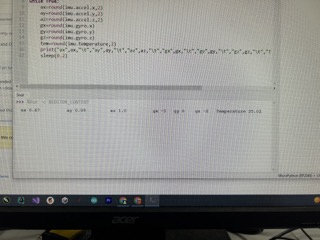
This is the video of the same thing:
Notice that in the video, the numbers changed drastically and very quickly when I moved the accelerometer.
RP2040 XIaO
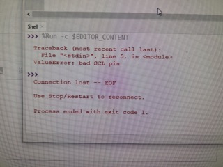
Then, I tried to get the RP2040 XIAO board working with the accelerometer. Using this video, I tried it on the windows computer. The code that they provided was the exact same as the working code with the Pico, except with a difference in pin number. However, I got this error message instead:
ValueError: bad SCL pin
This is the same as the website I found earlier that gave me a working code, except it is in github.
After a while of failing, I looked around the online forum to find anything that could help. A user by the name of davekw7x posted something interesting. He mentioned (although it applied to the Arduino IDE) that the XIAO contained 2 i2c ports, i2c0 and i2c1, and that pins 6 and 7 that have SDA and SCL built-in pins on the XIAO are not compatible with i2c0, and hence didn’t work. His solution was to change the actual library of the XIAO. However, since I was in Thonny, I couldn’t navigate to the library in the Terminal. Also, it was dangerous to do so as I might accidently corrupt the file, so I decided to not follow through on this potential solution.
For context, one of the main errors I am getting is this:
After asking ChatGPT the problem, it told me to change the pin number for the SDA and SCL to 20 and 21. While that eliminated the bad SCL pin problem, it still did not get rid of the no MPU detected problem.
After playing with the pin numbers (switching them around, changing them, etc), I figured out that the SCL pin wasn’t actually defunct. It was probably a code issue.
Since the code worked with the Pico microcontroller, and the hardware proved itself to be working, it was hard to figure out if it was a hardware or software problem.
I went to digikey website again, and then reuploaded the guy’s code again. I changed the pins accordingly to 20 and 21. The code did not give me errors, but it didn’t return anything. Now, I see why Thonny was unable to detect the MPU.
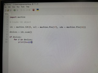
ChatGpT suggested the following code block in order to return a list of any devices detected on the I2C bus:
import machine
i2c = machine.I2C(0)
i2c.scan()
It says that “If it returns an error or an empty list, there may be an issue with your I2C bus configuration”
After finding the seeed studio’s data sheet, they said that the SCL pin is supposed to be configurated to 5, and the sda pin is 4. I tried doing that, but it still gives me an empty string when I checked for the storage location.
Adam Durrett told me that the pin numbers might be switched in Adrian Torres’ pinouts, or that pin 6 and pin 7 are switched on the pinouts of the Arduino. I tried to switch the pin numbers.
Dylan Ferro told me to re-watch the video, so I did that, but then my Mac had a sudden problem where the configure interpreter (insert picture here) does not work, even when I put the Seeed was in bootloader mode, where the menu to install the configuration was supposed to appear.
I suspect that mhy Mac’s unresponsiveness was the underlying cause of the problem. As seen in the picture, the tip that Adam Stone told me about earlier to configure MicroPython doesn’t work anymore, and I literally cannot connect the Seeed to my machine.
So, I went to a windows machine, watched the video through, and miraculously, the accelerometer worked.
Now, I realized my mistake yesterday. I thought the code was the same for the Pico and the XIAO. What I didn’t realize was that the I2C pins for the Pico is programmed under bus 0, and the XIAO is programmed under bus 1. As denoted by this line of code right here:
 i2c = I2C(0, sda=Pin(16), scl=Pin(17), freq=400000)// Pico code

 i2c = I2C(1, sda = Pin(6), scl = pin(7), freq = 400000) // XIAO code.
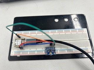
After making this change, the accelerometer worked, albeit it didn’t work flawlessly, as the Seeed that I used wasn’t soldered on to its pins, so it only managed to work sporadically.
This is the video for the accelerometer on the XIAO:
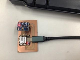
This is the current wiring for the XIAO:
Milling out the board
Next, I am going to design the board in KiCAD, which should not be hard because I don’t need to connect any inputs onto the milled board.
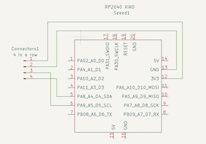
So I went to KiCAD in Eeschema, and designed my circuit. The circuit is fairly simple as it was the same build for all my previous models. There was one power and ground pin going into the VCC and GND, an SCL and SDA pin that runs between the Seeed and the MPU6050. The Eeschema circuit is presented here:
The footprint of the pads are as follows:
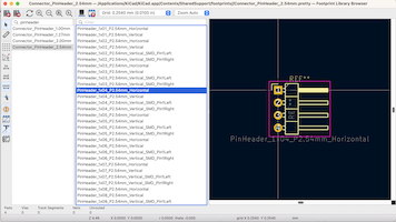
I planned to solder on female connectors on to the pads so that the MPU6050 can be attached on to the milled out board. The seeed will be soldered on as normal.
KiCAD design:
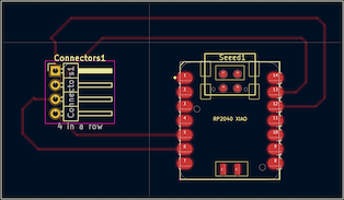
This time, I had very little struggle with designing the board, as I became more familiar with the software.
Bantam
Next, I went over to Bantam tools and downloaded my KiCAD gerber files into the software. I followed the milling workflow and zeroed the bit, measured the z-stock thickness, and rendered the front copper and edge cuts files.
However, right as I was about to cut, I received this warning:
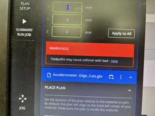
I realized that the offset setting was -1.3mm, instead of 0.01mm. -1.3mm would in theory cut through the stock and into the metal bed.
After changing the settings, I got this preview:
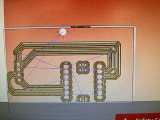
I thought everything was fine so I went ahead to press start. However, I noticed something wrong immediately, as the bit started cutting extremely close to the side of the board. I stopped the cut, and realized that somehow, my design is rendered wrong. As the previous picture shows, it is all the way to the left (there must also have been something wrong with the machine, because it is offsetting to the left more than it should.)
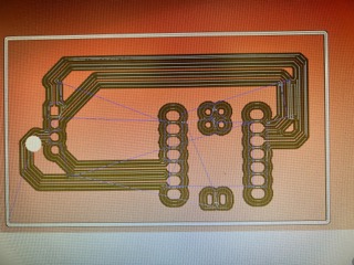
So, I shifted my design to the rightward and upwards direction:
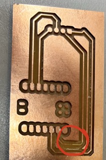
However, after I milled and deburred my board, I realized that one of the copper traces have been ripped:
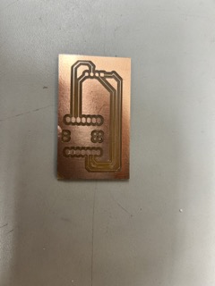
As a result, I had to repeat the process all over again. Luckily, this time, the board finally turned out well:
Soldering
Soldering was very simple:
Here is the complete solder job:
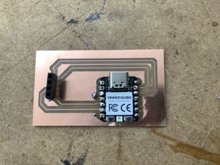
As you can see in the last picture, I soldered the female ports on to the pads on the milled board. In order to do this, I first put a blob of solder on the pads first, and then held the ports in place to heat up the blob until it held up by itself. I repeated the process for the other pins as well.
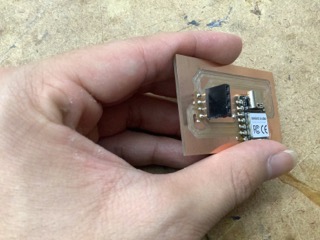
This is the final result:
When I uploaded and ran the code, it worked out beautifully: