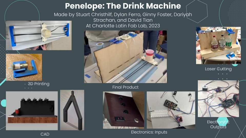
Week 10 Students B: Machine Week
This week’s group assignment is to make a machine. Our group made a soda mixing machine and the process can be found below. The project members were Dariyah Strachan, Dylan Ferro, Ginny Foster, Stuart Christhilf, and David Tian.
Slide
Video
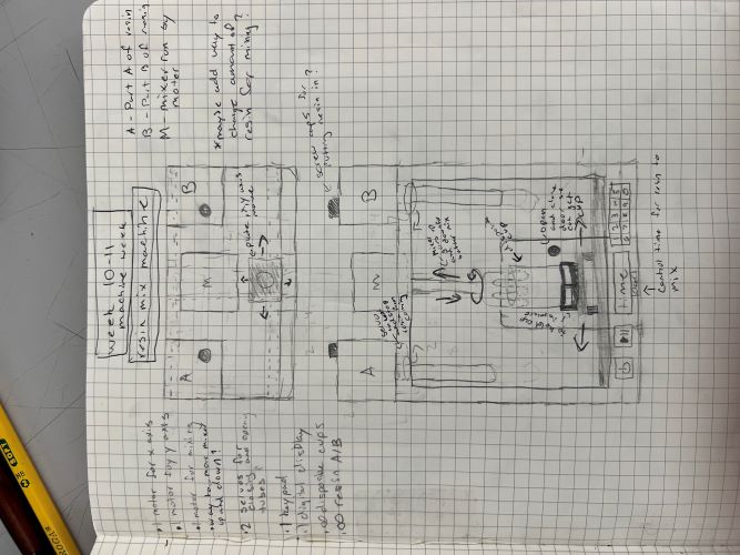
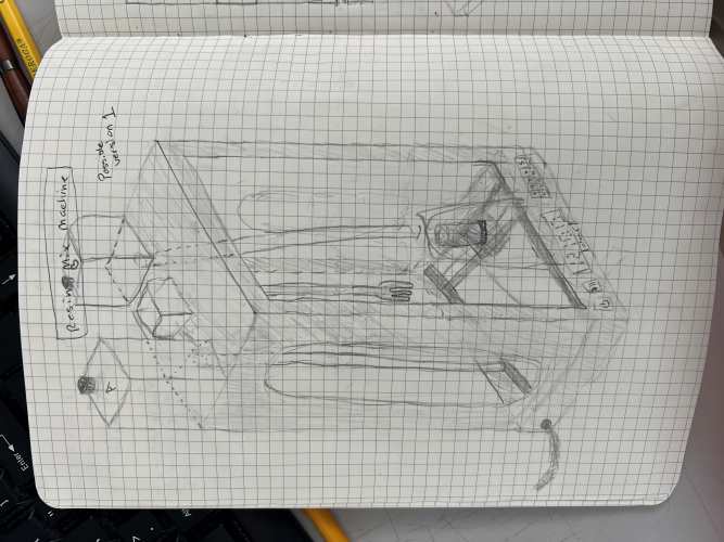
Initial Idea
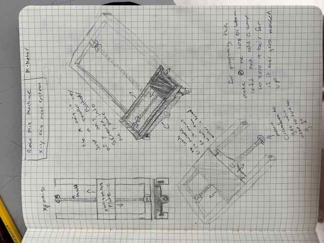
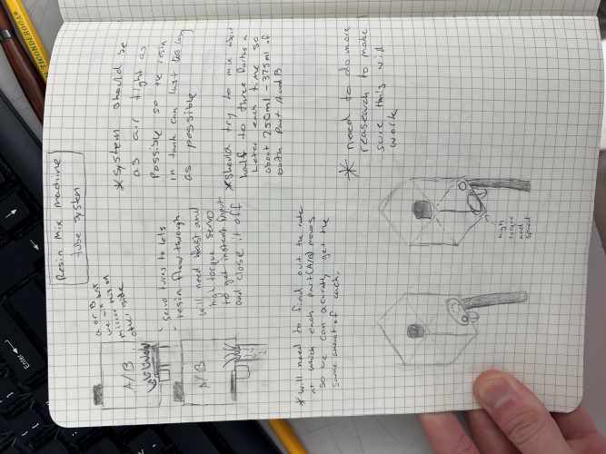
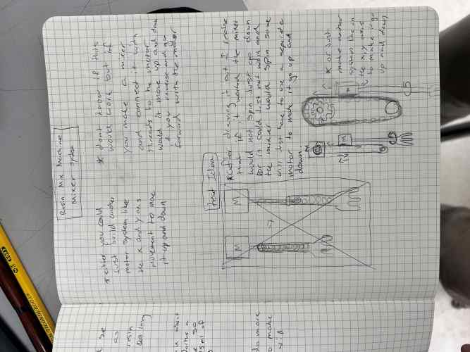
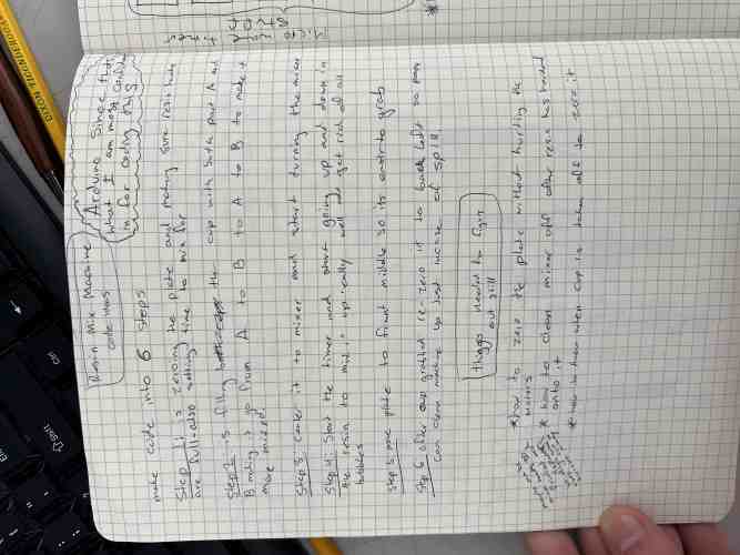
Our originial idea was to make a machine that poured resin into a mixing cup and then mixed it together. Our machine would do this by moving to the pour spout for part A, pouring part A, moving to the spout for part B, and then pouring part B. From there it would move to the middle where a mixer would mix the two parts together and initiate the exothermic reaction. Once done mixing the machine would return the resin mixture to the user to pour. We decided to pivot over concearns about the price of a pump that would pump viscous resin parts A and B, and the cleaning of the machine and tubes.
Group Planning: Group
Sketches: Stuart
Housing: Ginny
The first and last thing I made for our machine was the back housing or the thing that holds the drink bottles behind the machine and also holds up the pumps above the cup. Originially, I started a prototype for a resin mixer that was our first machine idea. You can see documentation for that on my personal site.
Initally David Tian was going to make the back wall that held up the pumps and I was going to make the drink bottle holder, but I realized that I could connect the back wall to the drink bottle holder so I took over both parts.
I began my design in Cuttle because I knew that a tabbed box we be the fastest and easiest way for our group to get housing and I knew that Cuttle had a tabbed box generator. I used the box generator that had six sides because I knew I needed all sides to have some type of covering. I started by typing in the dimensions of the drink holder part of the housing. I made it 25” long x 5” deep x 3.33” high because that is what our group thought the measurements should be and these measurements also align with the button control pannel so the two would seemlessly fit together (screenshot 1). With that I could begin editing the tabbed box Cuttle made me. I began by measuring the diameter of a 2 litere soda bottle so I could take that measurement and turn it into a hole for the drink bottle to sit in. With that measurement I dragged out a circle and changed it’s diameter to 4.4” which was slightly larger than the bottle’s diameter (screenshot 2). I copied and pasted that circle two more times and then dragged it onto one of the top faces of the box. I moved them to the center of the top lid because I knew we needed space for the electronics in the final machine. From there, I added a rectangle to one of the short sides of the box and made it’s measurements slightly smaller than the outline of the tabbed box (screenshot 2). This was for the electronics so that the wires from the back of the buttons in the control pannel could connect directly into the electronics storage in the drink holder.
 Next, I added two lines to extend the tabs of the side of the short box because when I tested my original box with a back wall design I did not account for the extra tabs which I needed to remove (see screenshot 6 below). From there I needed to make one long side of the box 14” tall to hide the drink bottle and act as the back wall. To do that I had to override the tabbed box algorithm that cuttle uses by clicking directly on that side of the box in the left hand menu, and then I could click on the side, scroll down in the right side menu until I saw the scale line of information. In the scale it has the varibles for the tabbed box, but I could delete one of the varibles and type in my own value to change it. This is what I did and I changed it to 14”. From there I was done in cuttle and I exported my file as a .svg. So I could do some final editing in Corel Draw.
Inside Corel Draw I clicked file, open, and then clicked on the .svg Cuttle file to open the file I made in Cuttle. In Corel Draw I used the segment delete tool from the left side tools menu to delete the tabs on the short sides of the box. I also removed the text labels from each box side because they were not necessary (screenshot 3). Once done I selected the entire design and made all of the lines hairline in the top bar so that when they get laser cut.
After Corel Draw I hit the print button on the computer to send the file to the laser cutter. I initially cut on cardboard to ensure my design was correct. When I hit print it opened the epilog printer interface and I began assigning the print settings. I imported the cut settings for cardboard by hitting the file icon and then I clicked on the vector cut settings for cardboard (screenshot 4).
 Next I foccused the laser cutter for the cardboard that I put on the cut bed. I did this by using the manual foccus on the laser cutter menu. Next, I hit send on the printer interface to send the design to the laser cutter. From there on the laser cutter I hit the play button to start the cut (screenshot 5).
After it cut, I removed all the pieces from the bed (screenshot 5, right). I then assembled the box by laying everything out and then hot gluing all of the pieces together. I placed the side wall against the bottom first and as Dariyah Strachan held the pieces together for me, I took the hot glue gun and went down the seam of the two pieces. We did this for all of the box parts and then let the glue cool (screenshot 7). On the first version I cut I realized the problem with the tabs and then made the fix I described above (screenshot 6). The second version was way better and so I went with the design for the final cut.
 To cut the final version I extended the back tabs on the top and bottom pieces because I was using 1/4” material for the back wall and the tabs needed to fit into the material. Everything else I kept the same because the wood I was using was going to be 1/8” like the cardboard. I following the same cutting procedure for the wood as I did for the cardboard except I imported the 1/8” vector settings for the 1/8” wood and the 1/4” vector settings for the 1/4” wood (see screenshot 10 and 11 below).
It is worth noting that I had to go and fetch some 1/4” wood from out lab’s wood shed. Because the piece was from a hardware store it was very large it had to be cut to fit inside the laser cutter. My instructor Mr. Tom Dubick used a table saw and cut it for me because we are not allowed to use the circular saw because it can take fingers off much more easily than a reciprocating saw or the table saw. I did have to set up the saw horses and put the wood on the saw horses, but that was not that hard because the saw horses had directions on them and I could lift the wood up on the saw horses myself (screenshot 8). After setting it up and drawing the cut lines Mr. Dubick can out and cut it for me (screenshot 9).
 After he cut the wood I took the smaller piece and loaded it into the laser cutter and then cut it. I also had to change the vector setting in the print interface to cut 1/4” wood (screenshot 11).
 After it was cut Dariyah helped me again hot glue the wood version together as best we could. Most of it did not need to be glued together because it was a perfect fit together with a little percussive maintenece but just to make sure it would stay together we put glue inside the top and inside the electronics hole (screenshot 12). From that the bottle holder was done and I tested to make sure that the 2 litere bottles fit in the holes and were hidden from the front. The holder was sucessful so we began putting things in it/on it (screenshot 13). My design files can be found below.
Drink Machine
Sketches: Group

Simulation: Stuart
Here is a 3D fusion simulation of what we originally though our project would look like made by Stuart Christhilf
Stepper Motors: Stuart
Stuart Learned how to code steppers during week 9, So now all he had to do was code it with a snap action switch so that we could zero the plate. After learning that a snap action switch just functions like a button it made it a simple input object making him able to tell when something was pressing on it. Here is a video of it working with the stepper motor.
Lastly after making sure that the switch worked with the Stepper Motor Stuart set it to the complete opposite saying it always runs unless the switch is pressed down to see if the plate would move and stop as soon as it touched the switch. Here is a video of it working and his code for it.
// Include the Stepper library:
#include <Stepper.h>

// Define number of steps per revolution:
int stepsPerRevolution = 50;
const int speed = 200;
#define LEVER_SWITCH_PIN 2
int pressSwitch = 0;
// Initialize the stepper library on pins 8 through 11:
Stepper myStepper = Stepper(stepsPerRevolution, 8, 9, 10, 11);
int buttonClick = 0;

void setup() {
  // Set the motor speed (RPMs):
  myStepper.setSpeed(speed);
  Serial.begin(9600);
  pinMode(7, INPUT);
}

void loop() {
pinMode(LEVER_SWITCH_PIN,INPUT);
pressSwitch = digitalRead(LEVER_SWITCH_PIN);
if(pressSwitch == HIGH)
{
if(buttonClick == 0){
  buttonClick = 1;

}
else if(buttonClick == 1){
  buttonClick = 0;
}
delay(1000);
}


if(buttonClick == 1){
  myStepper.step(stepsPerRevolution);
}

if(digitalRead(7) == HIGH){

  Serial.print("safhuahgufdna");
}
}
Pumps: Stuart
After Stuart learned how to code the stepper motors the next step was coding the pumps. Luckily the pumps we used are just simple DC motors that are input and output, so he could learn through just plugging it into the digital pin of an arduino Mega and ground.
The next step was to learn how to actually program them. To do this we connected 2 more pumps, so we could work multiple together and taking inspiration from a game called Minecraft made an infinite water source. By making them take and spit out water from one to another. Then I just had to put this code in for it to work. Here is my code a video of it working.
#define pump_one 7
#define pump_two 8
#define pump_three 9

int turn;
void setup() {
 pinMode(pump_one, OUTPUT);
 pinMode(pump_two, OUTPUT);
 pinMode(pump_three, OUTPUT);
 turn = 0;

}

void loop() {
digitalWrite(pump_one, HIGH);
digitalWrite(pump_two, LOW);
digitalWrite(pump_three, LOW);
delay(1000);
digitalWrite(pump_one, LOW);
digitalWrite(pump_two, HIGH);
digitalWrite(pump_three, LOW);
delay(1000);
digitalWrite(pump_one, LOW);
digitalWrite(pump_two, LOW);
digitalWrite(pump_three, HIGH);
delay(1000);
}
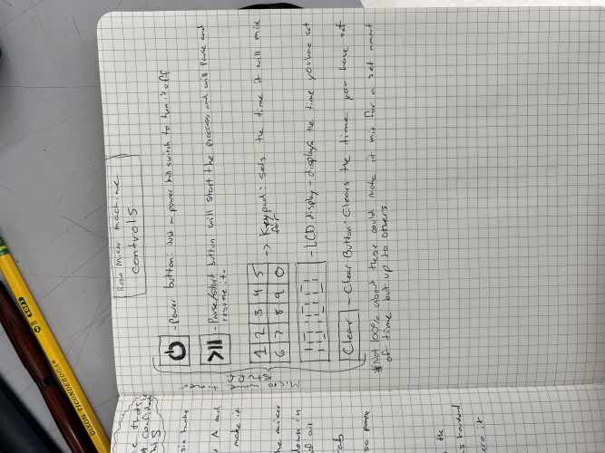
Button Control Pannel: Ginny
I began by making the control pannel that would hold the buttons. The pannel needs to hold the on/off button, the start button, and the three buttons for the different sodas/syrups. I began in Fusion 360 where I made a base rectangle that was 5.7 inches by 5 inches (screenshot 1).
 I then extruded that up an arbitrary height that looked right because the height did not matter (screenshot 3). This ended up being 3.29 inches tall. From there I used the draft tool from the modify drop down menu to get a ramp down on the rectangle I just made. I selected the pull direction as the bottom face and the faces as the front face where I wanted the ramp to be (screenshot 4).
 From there, I shelled the inside of the triangle I made using the shell tool from the modify drop down (screenshot 5). Next to make the cylinder holes I used the cylinder tool from the create drop down. To use it I selected the sloped plane as the plane I wanted it on and then selected the middle of the face as the center point and then the diameter as a little large than I measured the button as (screenshot 6). To measure the button I used a pair of calipers. From there I dragged the cylinder down to intrude it and cut into the sloped plane all the way through. Next, I used the rectangular pattern tool from the create drop down to dupliacte the cylinder hole three times. Inside the rectangular pattern dialog box I changed the object type to features and selected the cylinder hole I had just made to pattern (screenshot 7).
 From there I could just choose three as how many I wanted and I could drag the arrow out until the distance of the three holes looked correct. Next, I I created a sketch on the top plane of the panel for the the other circular button but I made this hole on the right side of the top button pannel (screenshot group 1). From there I added a rectangle in the sketch enviroment and the hit shortcut letter “e” to take me directly from the sketch enviroment to the 3D workspace where I could intrude the button holes by entering a negitive value for the extrude command (screenshot group 1).
 From there I was done so I could 3D print the control pannel. I did this by exporting the file as an .stl from inside Fusion by hitting file, then export.
To get the file ready to print I opened Prusa Slicer. Inside prusa slicer I added supports everywhere but after printing it I realized that if I had rotated it I would not have needed supports, but the day I did this on was very long and personally stressful which is why I didn’t pick up on that when I sliced it. Once I changed the infill to 5%, and the quailty to .20 mm speed I sliced the design to turn it into G-CODE (screenshot 9). With the G-CODE I could then upload that to our 3D printers’ website for the printer I wanted to use. Once uploaded I wiped down the bed of the printer with alcohol and then hit print inside the printer’s website. With that I let the design print and came back once it was done (screenshot 10).
When the print was finished I removed it from the bed with a spackle knife. Next, I had to remove the supports and because they were hard to remove by hand I also used the spackle knife to pry off the supports (screenshot 11).
From there we could add the buttons into the control panel and with that the control panel was complete (screenshot 12).
 Though one of the buttons did not totally fit inside the hole because the sides of it were wide and I thought it would just push in. To make it fit Dylan Ferro sanded down the inside of the button hole a little bit until the on/off switch fit in.
Drink Bed Plate: Dylan
End Caps: Dariyah
v1:
After I found a size that matched the extrusions we would be using, I then used those dimensions to create a end plate that consisted of one end piece on on side, I 1in block connected to a block that was about 8in across. After I had an L shape, I made a construction line down the center of the middle connector and I mirrored the joint to connect the extrusions to it. Once I had that design I printed it to see if it would work for the project and tested it.


test 1:
The first iteration of the endcap design was mildly off, so when the extrusions were inserted it cracked.
v2:
To fix the problem mentioned earlier, I slightly adjusted the size of the each of the inner walls of the endcap by 2mm on all four sides. I then printed it and tested it
test 2:
This end cap fit quite well and we used it for initial machine testing.
v3:
The next change to the design I made was adding a space for the motor to sit while moving the bed plate across the machine.

test 3:
This addition of an area for the motor fit the motor well enough, but with the way we wanted to orientate the motor, there was a problem fitting the port in for the cords.

v4:
To fix the port issue, I simply made a slot for the port to fit into.

test 4:
This time everything fit nicely and this was used for the final product.
v5
The next thing I needed to add to was a slot for the opposite side of the belt where the spool would be. To do this, I used the v4 design and the construction lines along with it as a guide. I settled on this design for the spool holder.
test 5
The spool holder was slightly too small

v6
I slightly opened up the space a little, so the wheel will not get stuck against the pocket made for it

test 6
This version worked and was used in the final product.

Wheel Holder: Ginny
Once our group felt like we wanted wheels to move and guide our machine, I began desiging a custom wheel holder for our T bar tracks. I started by looking at a metal bracket and using calipers to measure it’s dimensions (screenshot 1). I used that bracket as inspiration for my own, but I added screw holes so that we could screw the drink plate on to the wheels holders.
I began designing in Fusion 360 by creating a sketch. Inside the sketch workspace I created a rectangle according to what I measured the metal bracket to be(screenshot 2).
 Next, I added a fillet to the corners of the rectangle, but only two of the corners (screenshot 4). The fillet tool can be found in the ___ menu inside the sketch workspace. Next, I began to add the little bump out for the single wheel. I started by measuring the distance from the top of the bump to the main body of the plate. Next, I added a center point rectangle from the create menu onto the top of the main body rectangle (screenshot 3). From there, I used the fillet tool to fillet the rectangle 9mm until it looked pretty close to circular on the filleted edges (screenshot 4). I also then deleted the uncessary lines of the rectangle using the trim tool from the modify menu (screenshot 5).
 Following that, I added the center circle for the screw in the filleted bump out I just made. I measured the distance from the edge of the inside of the circle to the outer edge of the curve and then refrenced that measurement to make sure my hole was the right size. I measured the distance from the outside of the bracket to the edge of the screw holes and then took that distance for the refrence lines. Where the two intersect is where the center of the screw holes needs to be A(screenshot 6). From there I hit shortcut letter “L” to begin drawing refrence lines. To make the lines refrence lines you have to change them to construction lines. To do this you hit the little construction line button in the right side tray inside the sketch enviroment (screenshot 7). I then added a circle by hitting the “c” shortcut. I added two circles and then dimensioned them according to what I measured the bracket wheel holes to be. I then hit “e,” the shortcut to extrude and I extruded the sketch up 2.5 mm (screenshot 8).
 With that made I created another sketch on the top surface of the piece I just extruded, I then projected the outer dimensions so I could refrence them by going create, project/include, then project (screenshot 10). I then added a circle by hitting the “c” shortcut. From there I added two screw holes in the middle of the main rectangle body to screw the plate onto the wheels (screenshot 9). I then hit “e,” the shortcut to extrude and I intruded the sketch down 6 mm (screenshot 11).
 Later though, these would be removed as once I had my final design Dylan edited it for his updated plate. Dylan also added an elevation step to the design so that the plate would not risk hitting the motor should the machine malfunction. Once I had the design done I extruded it up and then added a rectangular box from the create menu to the bottom of the design, like the bracket had, but this later got removed because it only added to the print time and did not really serve a purpose (seen in screenshot group 1 and screenshot 12).
With my design done, I saved it as an .stl and imported it into Prusa Slicer. Inside Prusa Slicer, I changed the infill to 5% to reduce on print time, and I also changed the quailty to .20 mm speed again to cut down on print time. From there, I hit the slicer button to generate the G-CODE. Next, I uploaded the design to our labs 3D printer specific website. Before printing, I wiped the print bed of the printer I wanted to use with alcohol, and then I hit the print button inside the website to start the print.
Once the print was done, I removed it from the print bed, and then I could begin attaching the wheel onto the holder. I did this using a pair of vice grips, and an allan wrench (affecionatly known as an ikea wrench :) ) (screenshot 12).
 I added the wheel and the spacer onto the bolt and then slid that through the hole in the plate. Next, I added the nut to the other side of the bolt and I held the nut in place with the vice grips so I could screw the bolt into it. From there I used the allan wrench to screw the bolt into the nut until it was fairly well attached. With one attached I did the other two using the same method. Then I could test it out on the T tracks (screenshot 13).
The first one slid very well up and down the T tracks, however if you put too much force on them, the tracks would derail which our group thought would be a problem because sometimes liquid can be discpetivly heavy. Knowing that I went back into my design and moved the two holes about first about .1 mm and then on the second try 2 mm in the direction of where the tracks would go. After making those changes I re-printed the design and after moving them 2 mm the tracks fit perfectly and did not derail.
After changing the plate design that would hold the cup, Dylan modifiyed my existing design to add some blocks to elevate the plate and remove the extra set of holes because the plate would just be glued to the wheel holders instead of bolted (screenshot 14).

The y-axis endcaps: Dariyah
For this I based my deign off of the Prusa mini Z axis endcaps. I used similar sizing as the Prusa mini’s (approximately 3.5in across) and I made a box with three holes total, two that had a tight fit for the metal dowels and a very loose fit for the z axis motor. That way, the motor will not grind against the printed piece. This only required one version and did not need to be redesigned.

Bearing holder: Dariyah
The next thing I designed was the holder for the bearings for the Z-axis. I printed this piece in 2 pieces so the bearings will both fit in place together. I simply made a rectangle where based off of the design of the Z-axis endcaps and kept the distance spacing the same between where the metal dowels went and created a space for the bearings to sit in. after that was printed the case was superglued together and placed on the metal dowels. this would allow the z-axis motor the move while staying in place.

Dariyah’s final files
all of my final files that I used to help create the machine are linked here
Pump Holder – David
Pump Research
I was tasked with coming up with a pump model that could pump the resin from the cups down to the bottle itself.
From the tabletop epoxy resin data sheet, Dylan Ferro found that the viscosity of resin is 11,000 cp (centipoise). This means that the resin is very viscous and the pump needs a lot of power in order to pump the resin from the cup.
Then, I found this video, which showed a person using a peristaltic-like manual device to pump out epoxy. But Dylan pointed out that the peristaltic pump would not work because a 0.5 inch tube would be under a lot of pressure, and the whole pump has to be made out of metal, so then we need to find something else that works.
I also found this website where someone used pumps to create a resin tap, much like a viscous water dispenser. But, it involves using a valve (solenoid) and many buttons, which was not convenient at all.
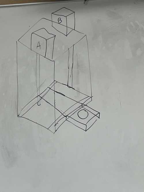
Idea change
Due to the difficulty of finding viable pumps, we decided to change the idea for our project.
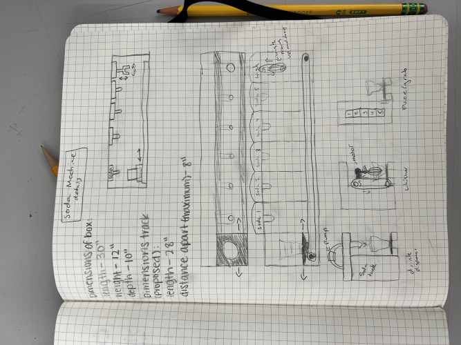
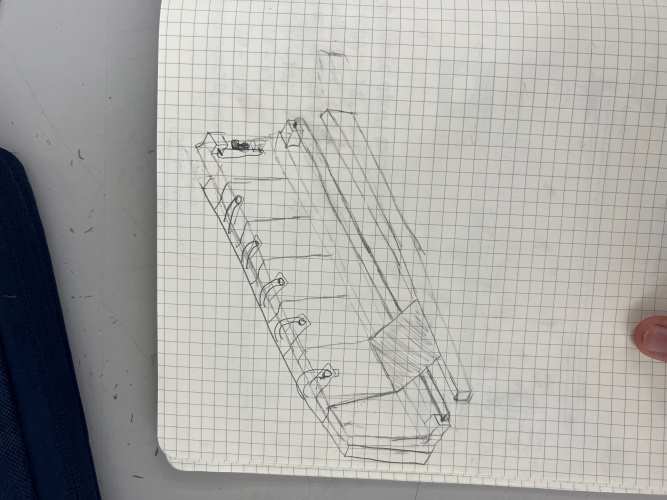
This is the new design, drawn by Stuart Christhilf:


Our new idea is a soda dispenser. When the user presses a button on the left, a cup will move under several tubes poking out of soda bottles. Then, each soda’s pump will dispense a certain amount of soda, before the cup moves to the right and the soda is mixed.
I will discuss how I made the holder for the pumps, the mixing device, and an extension for the mixing motor.
Final Pump Model
We settled on this pump model:

It is just tubes attached to a regular DC motor, and it was compatible with water, which we tested with it:

The water flowed out smoothly, and we found that the optimal range for the pump is around 9 volts (it is a 5-12 volt pump).
The pumps will go on top fo the machine (refer to Stuart’s sketch).
Designing a Pump Holder
Next, I have to design a pump holder for the individual pumps, as they need to stay in place.
In order to model it realistically, I first made a bottle in Fusion360:

This is a cross section of the bottle, which is just a box extrusion with a neck on top of it.
Next, I designed a model pump by first developing the shaft of the pump:

The band in the middle is made using an emboss. Then, I made the 3 inverted arcs at the head of the pump:


The tubes on the pump are also made using emboss and extrusion. The one on the side is made first by creating a plane that was tangent to the pump, and then extruding a sketch on that plane.
Then, I made a model wall on top of the bottle, in which the bottle’s top will poke out from above a hole:

To make putting the bottle inside the wall a bit easier, I made an opening in the wall and tried to put the motor on top of the opening of the bottle:

Dylan pointed out to me that the carbonation from the soda might interfere with the pump, and so I probably had to put the pump on its side instead of putting it straight up from the bottle.
I then deleted the wall and just made a platform above the bottle, and made a similar-looking arc from the side of the board in order for the bottle to slide in from the right side.
Next, it was time to make the C-clip to press fit the motor. It is basically an arc that partially encloses itself above its bottom hemisphere. Below are the dimensions for the 2D sketch of the C-clip, determined from measuring the size of the pump:


As you can see, I made concentric circles with lines going across them. They are rotated 5 degrees above the halfway diameter to give the C-clip strength.
Then, I just extruded c-clip in order to make it 3D. This is the finished product:

I printed the piece out and tested how well the motor will hold:

I found that it didn’t held the pump very tight, and so I made an addition to my design. Notice that the metal part of the pump has a smaller diameter than the white plastic part. So, I made a small c-clip behind the original one:

Then, I extruded it based on the length of the plastic part. I decided to also rotate the side a bit more upwards.
So, I first made a midpoint plane between the two sides of the C-clip, and drew a line on it. Then selected the top of the two sides and selected that line as my rotating axis:


Then, Stuart printed out that I had to make a gap underneath the pump holder in order to fit the wood/acrylic.

I also made 1 inch deep 5 mm holes in order to put the screws into the print and secure it against the wood:


I printed the second version out and it did fit better than the first version:

I printed out a couple more pump holders for the other soda cans later on.
Soldering the Pumps
I also helped to solder wires onto the pumps themselves:

The shredded core wires are soldered to the pump, and their other ends are twisted with the regular jumper wires and soldered together.
Designing the Mixer – David
Next, it is time to design the mixer that is going to mix the soda drinks together. First, I took into account the dimensions of the red party cups that we are using:

I drew the 2D sketch for the mixer, which resembles a tuning fork:


The top of the mixer is going to go into the motor, so the sizing of the hole was important. At first, we planned to use a high-torque, low speed motor.
I measure the size and width of the motor that is used for mixing the drinks together:


Then, I made a Fusion360 sketch of a series of different hole sizes in order to see which one would fit the best:

The above image shows the dimensions.

It looks like the middle hole fits the motor best.
Motor Change
However, just as I was about to input the correct dimensions on to the tuning fork, we changed the motor model for mixing the drinks, and I had to repeat the process again.
This motor has a plastic part that fits into the hole perfectly, and I measured the inside diameter of it:


Since I knew that the diameter won’t likely be perfect, I designed a series of different sizes in order to determine the correct size:


I settled on the final size of 2.50 mm:

This is the final version of the fork:

I printed out the tuning fork, although it didn’t have supports. The result was that the hole was a bit squished, and it didn’t really fit into the mixing motor, due to the elliptical shape of the hole:


As you can see in the picture, it takes a lot of strength to force the tunning fork into hte motor, so the first version of it was impractical.
Also, I found that the mixer was too short and Stuart suggested that it reach 3-4 cm above the top of the cup.
So, I made my second version longer:

I also generated a support around the hole of this fork by first using the paint on support feature in the PrusaSlicer software:


I printed out the second tuning fork, which also had horizontal beams to avoid flimsiness. And its top fits into the 5 volt mixer motor.

Designing the Extension for the Mixer – David
Next, I have to design an extension that holds the mixer motor.
On the right side of the machine, there will be a mechanism for mixing the drinks. A 5 volt motor (the one seen in the last picture above) will be attached to a Z track controlled by a stepper motor. The stepper motor will be able to control the height of the motor, which holds the mixer, which goes into the red cup.
The extension of for the motor is needed as the mixer is actually at the center of the X - track, which Ginny, Daryiah, and Dylan built. Since this track has a certain width, the extension had to be 150mm long in order to reach the cup.
First, I made a 2D sketch for the C-clip of the mixer motor:


The extrusion process of the C-clip is similar to that of the pump holder (using a mid-plane and the rotation tool).
After extruding the press fit, I made the other side of the extension. I had to include holes in this part because there screws are needed to attach the extension to the vertical axis:

I extruded that piece and the final product is this:

However, I failed to consider one aspect of the vertical axis. There was a protrusion on it which made the screws unable to go through the screw holes in the extension piece.
So, I had to remove a portion of the end piece, which I achieved after extruding an arc:

Now, the end piece was able to fit into the Z-axis:

Acrylic Trouble
When I made the pump holders, I left a gap in the front of it in order to affix it to the machine itself by inserting either a piece of wood or acrylic underneath the piece and securing it with a screws.
However, this turned out to be a mistake as there was not enough space on the pump holder for the screws to go through it and secure the acrylic seamlessly with it:

In the picture, you can see that the curve of the white pump holder prevents the acrylic’s side from fully reaching the bottom of the pump holder. This means that the hole drilled into the acrylic cannot line up with those on the pump holder.
Speaking of drilling holes, I found that it was really difficult to drill holes into the side of a piece of acrylic:

I had to do this step as I originally planned to put screws into the sides of the acrylic as well. However, it was very difficult to drill into the side as the drill bit cannot stay straight. In this picture, the drill bit snapped because it came out of the acrylic at an angle. When it tried to pull it back out, it broke.
When I used a larger bit, I was able to get down around 0.5 inches, but the material eventually cracked open when I tried to pull the bit back out.
So, this idea kind of failed.
In order to secure the pump holder, I decided to just laser cut out a piece of 1/8 inch plywood. I first figured out the distance between the two holes, and then drew a corresponding sketch in CorelDRAW and conducted the cut:


In the end, we didn’t use the plywood that I cut out and just let the holders hang on top of the back wall, which worked fine.
The project was spread out over 2 weeks and completed just in the nick of time.
Files – David
Here are my files for machine week.