11. Machine design
We are tasked with building a machine this week. Having 2 teachers on our team (Zack and Adam) they wanted to focus on a problem our student deal with each day. Shorts from copper burrs on our lab’s milled board.
For a better quality video you can check out this link
We are going to build a pcb buffering machine
Zack Budzichowski: Frame, wire drive and Carriage Design/Construction Dan Stone: Frame Design/Construction, base platform design and ESC DC motor Code Adam Durrett: Electronics Design and Stepper Code
Research
We did not find any good example of buffering machines for boards.
We do know what cleaning with board with an lightly abrasive materials will get rid of the burrs but not hurt the board.
Our brian storming after the class led us to 2 possible design
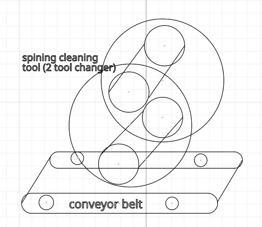
1) A tool set up similar to a drum sander. We would have a conveyer belt move up and down with 2 or 3 different spinning tools that would spin over the pcb to remove stray burs.
2) 3 axis machine (similar to 3D printer/milling machine) with a spinning brush
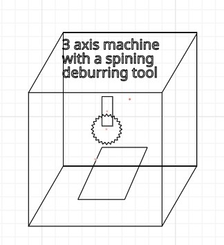
We debated the pros and cons and decided that a 3 axis machine will offer us a lot of expansion options as well as allow us to use a lot of existing design and parts knowledge.
We also wanted to explore some of the innovative areas Prof mentioned in the class and so we aspired to use:
-
Core XY mechanics
Setting up group work
We established a group project in Fusion and set up a private channel in matter most to help facilitate the work.
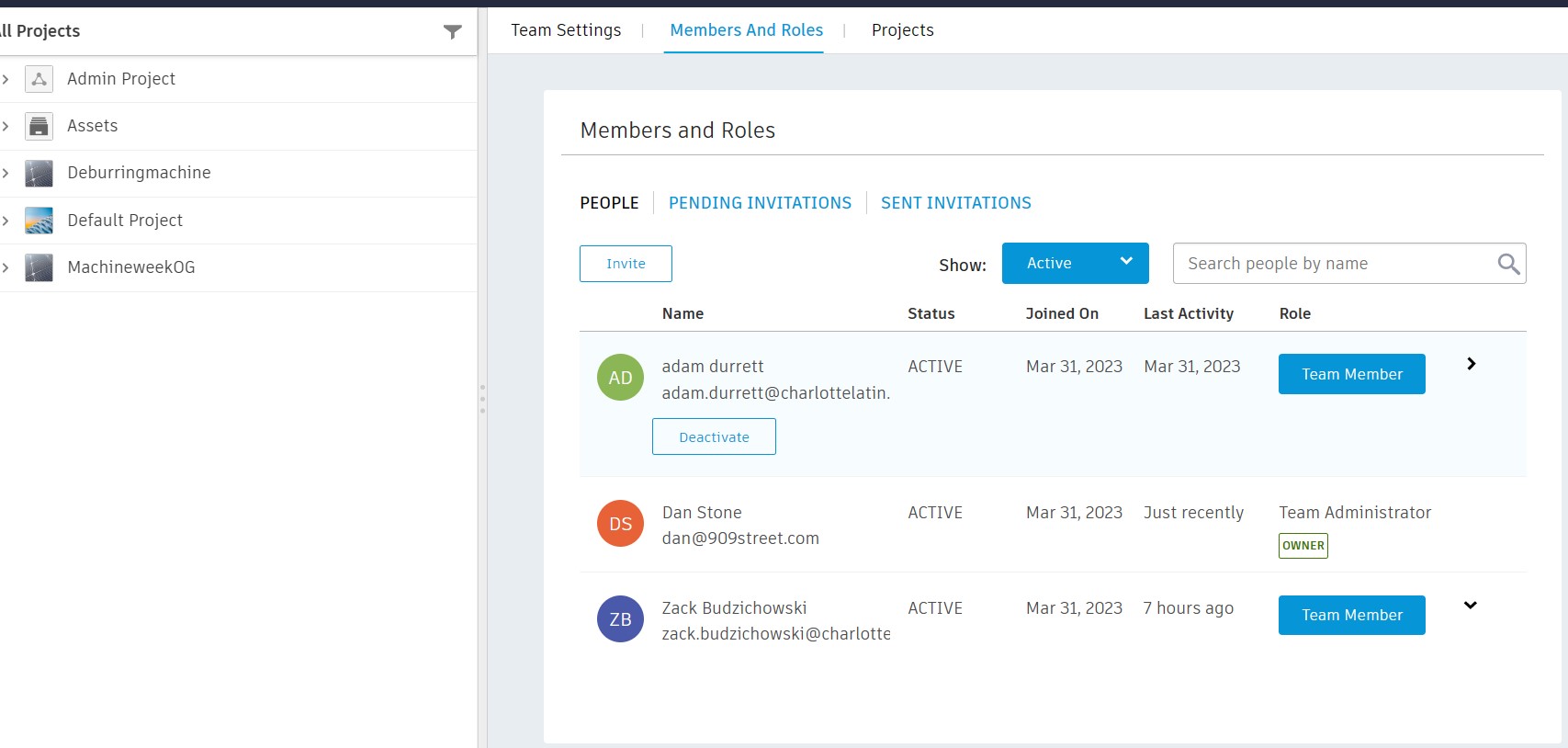
I added a private group on matter most and we are ready to go!
Design
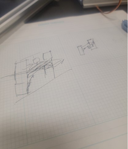
Our base design is a box with a top CoreXY mechanism based on the following design from the Urumbu project:
Our sketchs:
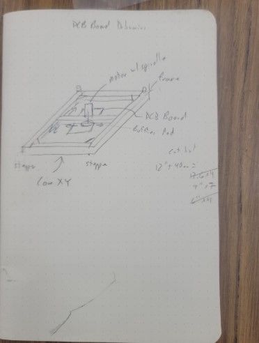
Zack turned it into a fusion design
parts
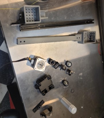
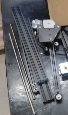
First we decided to see what we have in the lab we can repurpose and found a partially disassembled only 3D printer and another mechanism left over from another machine.
We completely disassembled this into parts we can potentially reuse
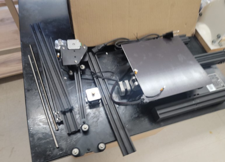
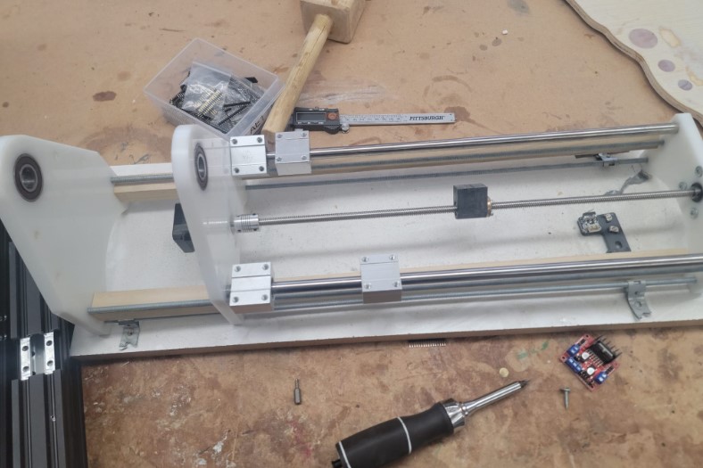
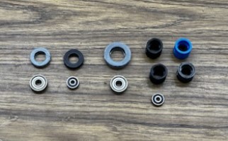
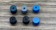
We recovered 6 stepper, a number of rails, threaded and non threaded roads and some wheels and bearings.
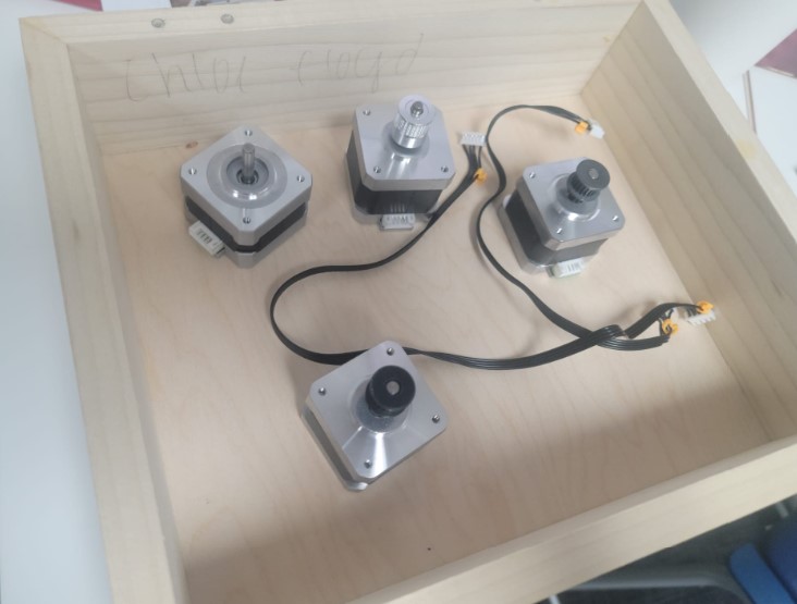
Testing stepper
Just to quickly make sure the stepper we recovered we quickly plugged them into an arduino and ran one of the stepper example codes to spin them.
#include <Stepper.h>

const int stepsPerRevolution = 200;  // change this to fit the number of steps per revolution
// for your motor

// initialize the stepper library on pins 8 through 11:
Stepper myStepper(stepsPerRevolution, 8, 9, 10, 11);

void setup() {
  // set the speed at 60 rpm:
  myStepper.setSpeed(60);
  // initialize the serial port:
  Serial.begin(9600);
}

void loop() {
  // step one revolution  in one direction:
  Serial.println("clockwise");
  myStepper.step(stepsPerRevolution*5);
  delay(500);

  // step one revolution in the other direction:
  Serial.println("counterclockwise");
  myStepper.step(-stepsPerRevolution);
  delay(500);
}
4 of the 6 were working well!!
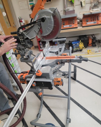
Part fabrication and assemble the body of the machine
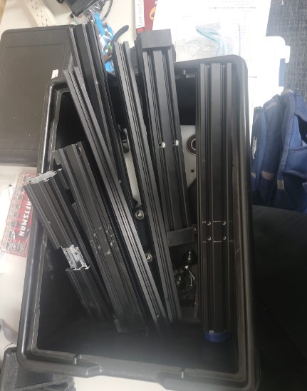
Our parts are going to be mainly either 3D printed, or the T slot rails we cut to size or laser cut. We augmented these with the parts we scavenged and a few thing we bought such as ball bearing and V wheels.
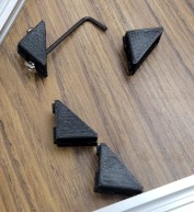
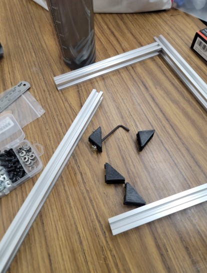
We 3D printed all the parts for the joints and carriages.
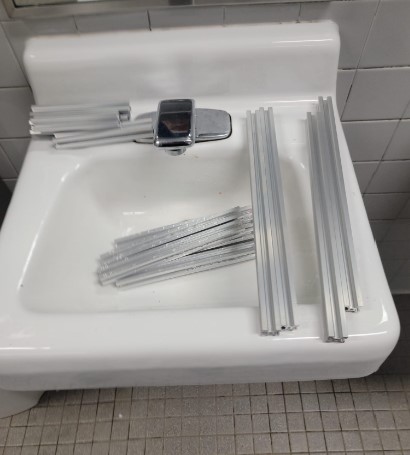
We would uses these together with the T Slots beams we cut to assumble
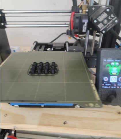
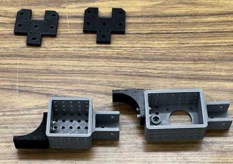
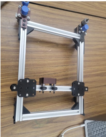
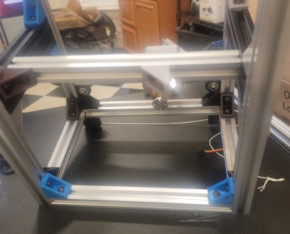
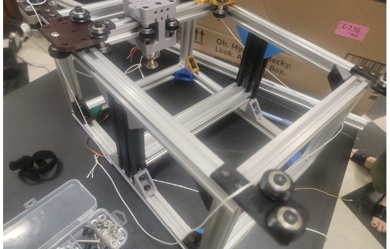
With the 3D printed parts we needed the T slots rails cut and then focused on assembly
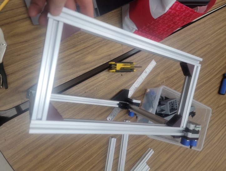
Now that we have them cut focus on using the 3D parts and wheels that we stripped from the broken 3D printer to assemble our base machine
We used the drill press to test a slot instead of a hole to get a tighter fit
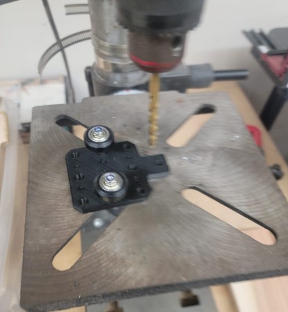

We then found out that the designers of the original part were a step a head and once we flipped the part we saw it already had a slot
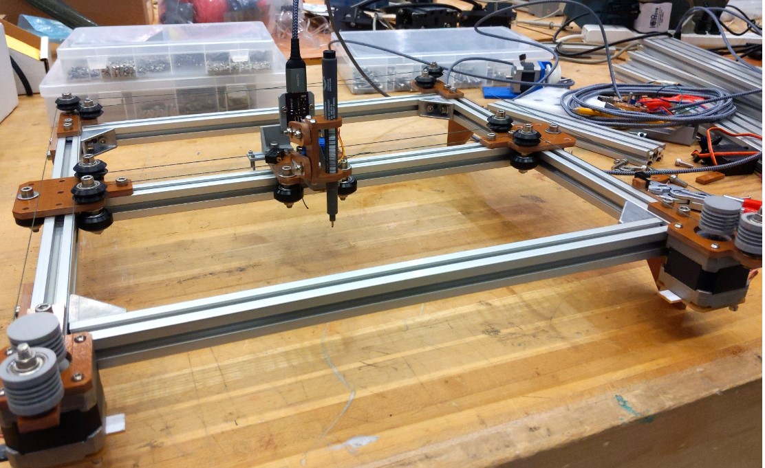
And we have a top frame
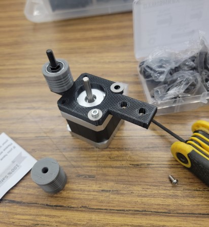
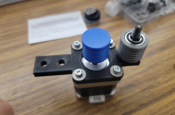
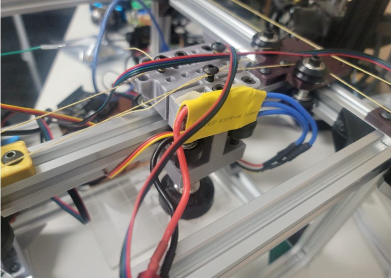
Wire drive
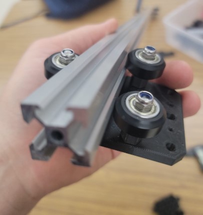
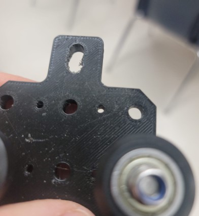
Our goal was to minimize cost by using 2020 aluminum extrusion with a Kevlar string drive system. I accidentally left the Kevlar string at the lab over the weekend and used some basic kite string I had lying around my garage for the rough manual build of the machine. The v-wheel bearing and pulleys turned out to be a bit tricky to mount correctly and get them all in the same approximate XY plane for smooth operation. As for the parts moving along the extrusion, it required a basic attachment and then a fair amount of fine-tuning to get the bearing wheels to move freely on the extrusions without binding or being too loose. There is a slot on the bearing plate that needed to be tweaked to get the right fit.
The largest issue that I had to overcome was aligning the motor capstan and pulley, so the string would be able to easily move with the motor yet stay in the correct grooves while spinning. After some trial and error I figured out that the ext of one pullet or motor needed to be equal distance between the prior and next groove in the assembly. After that it was just a matter of figuring out the best attachment method to the carriage string holder which turned out to be attaching the wire to a bolt screwed in the carriage string holder.
None of the work was extremely hard, but it did require patience and attention to detail.
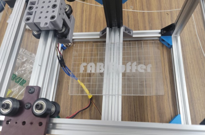
Base platform holding the board (3D print/Laser cut)
We needed to have a strong base on which the board will sit to be buffed.
We decided to have this Z axis manually adjustable and will use double sided tape to hold down the PCB similar to milling machine
We used one of the double wide rails that we stripped from the 3D printer
We cut it down to side and used 3d printer brackets and T Slot screws to hold it in place
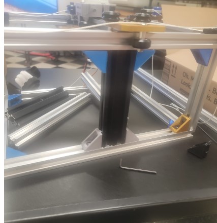
For the cross based we used the same brackets and screws and that will allow us to have Z axis manual adjustment when needed
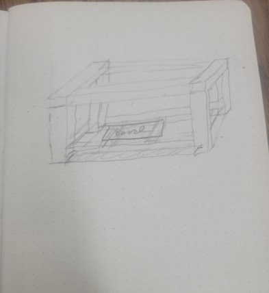
Now that we have a platform in place we can design a base plate.
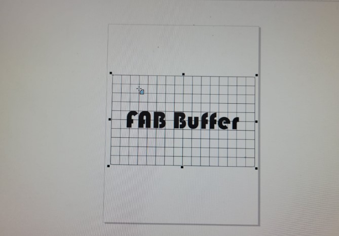
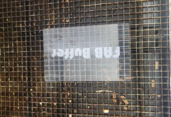
We had a 0.25 inch plexiglass leftover pieces in the lab we can use
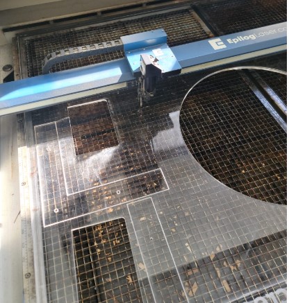
Got the laser focus and ready to cut
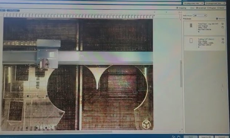
And here we go we have a plate
Next we need to secure it to the base platform
Used counter sink drill bit so we can use M5 screw and still have a flat surface
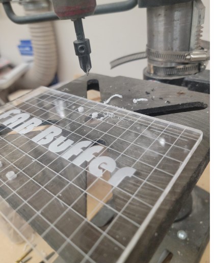
And here we go:
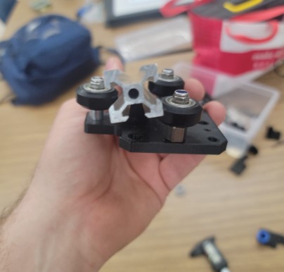
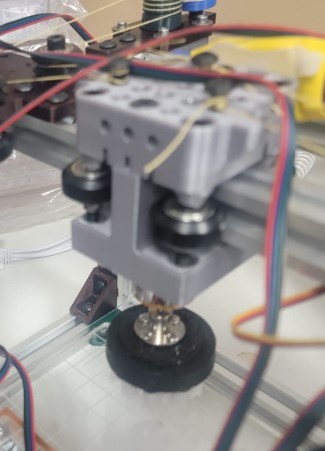
Motor carriage
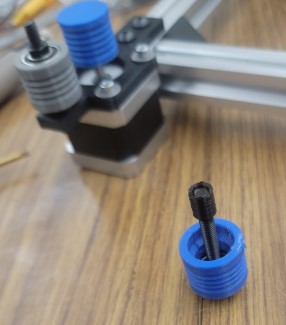
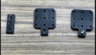
Here is a copy of the under carriage spindle mount that I created for this project.
We took the original carriage string holder model and modified it to add space for a bolt attachment to the spindle mount. We also added 1.5 mm (39.5mm to 41.0 mm) to the bolt spacing on the main carriage axis.
Here is a Fusion a viewer of the final design.
It took five iterations to get a working design and we could have kept going to optimize it, but time constraints dictated otherwise.
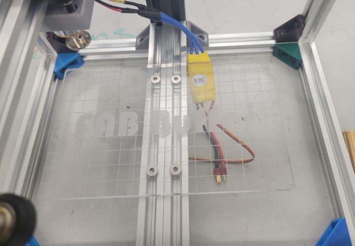
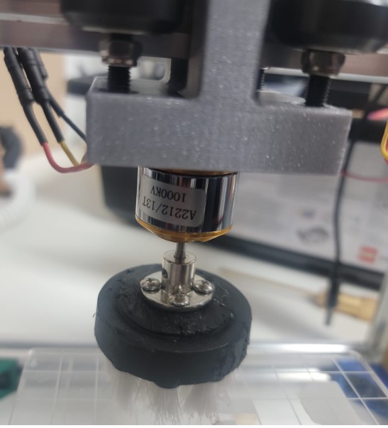
Cleaning head and code the controller for ESC/Brushless motor
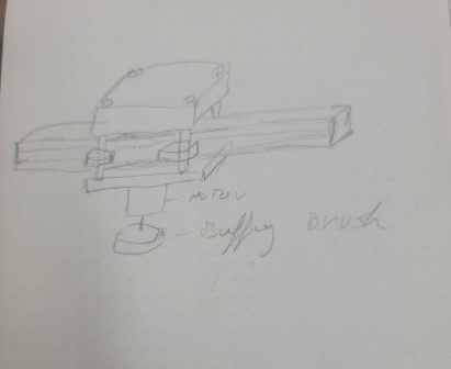
Here is the design for the cleaning head and carriage
For the cleaning head we decided to us a outrunner motor and ESC typically used in quadcopters we found on amazon - Xiangtat A2212 1000kv Outrunner Brushless Motor + 30a ESC Electric Speed Controller Set for Rc Aircraft Plane Multi-Copter Quadcopter
The data sheet for the motor is found here
We tested a dremel buffing head but found the resutls not so great
and so decided to go with a plastic brush that was originally set up for a drill. Once we had the motor to the carriage I focused on getting the code on an arduino to control the ESC
The ESC uses pulses to control the speed similar to have a servo control roatation. I asked ChatGPT for code that would drive the motor at half speed got the following:
#include <Servo.h>

// create a Servo object to control the ESC
Servo esc;

void setup() {
  // set the baud rate for serial communication
  Serial.begin(9600);

  // attach the ESC to pin 9
  esc.attach(9, 1000, 2000); // the second and third parameters are the minimum and maximum pulse widths

  // wait for the ESC to initialize
  Serial.println("Initializing ESC...");
  delay(3000);
}

void loop() {
  // set the speed to half of the maximum (which is 180)
  int speed = 90;

  // send the speed to the ESC
  esc.write(speed);

  // wait for the motor to ramp up
  delay(2000);

  // print the speed to the serial monitor
  Serial.print("Speed: ");
  Serial.println(speed);

  // pause for a moment before starting again
  delay(5000);
}
It is very important to have the initialization step as this would not work without it. It also would go to full speed and the slow down while I wanted it to start up slow and speed up. A small change to the code helped get that in line
#include <Servo.h>

// create a Servo object to control the ESC
Servo esc;

void setup() {
  // set the baud rate for serial communication
  Serial.begin(9600);

  // attach the ESC to pin 9
  esc.attach(9, 1000, 2000); // the second and third parameters are the minimum and maximum pulse widths


 esc.write(40); //added to slow down at start up


  // wait for the ESC to initialize
  Serial.println("Initializing ESC...");
  delay(3000);
}

void loop() {
  // set the speed to half of the maximum (which is 180)
  int speed = 0;

  // send the speed to the ESC
  esc.write(speed);

  // wait for the motor to ramp up
  delay(2000);

  // print the speed to the serial monitor
  Serial.print("Speed: ");
  Serial.println(speed);

  // pause for a moment before starting again
  delay(5000);
}
We tested different speed and found that 70 was the optimal
You can find the code file here
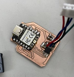
Electronics
Read the full breakdown on the Electronics Design Process Here on Adam Durrett’s FabAcademy website. We initially had the intention to use the Urumbot as a template for how we would build this machine. The electronics would be slightly adapted versions of the Urumbot’s, but with the exception that the motor controllers would run using the xiao rp2040 as opposed to the SAMD11. Hopefully, this would provide power via the USB-C port on the xiao, which would supply power to the motor and motor controller.
We went through 4 design iterations to in an attempts accomplish it. Designs 1 -> 2, 3, and 4, respectively:
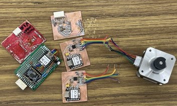
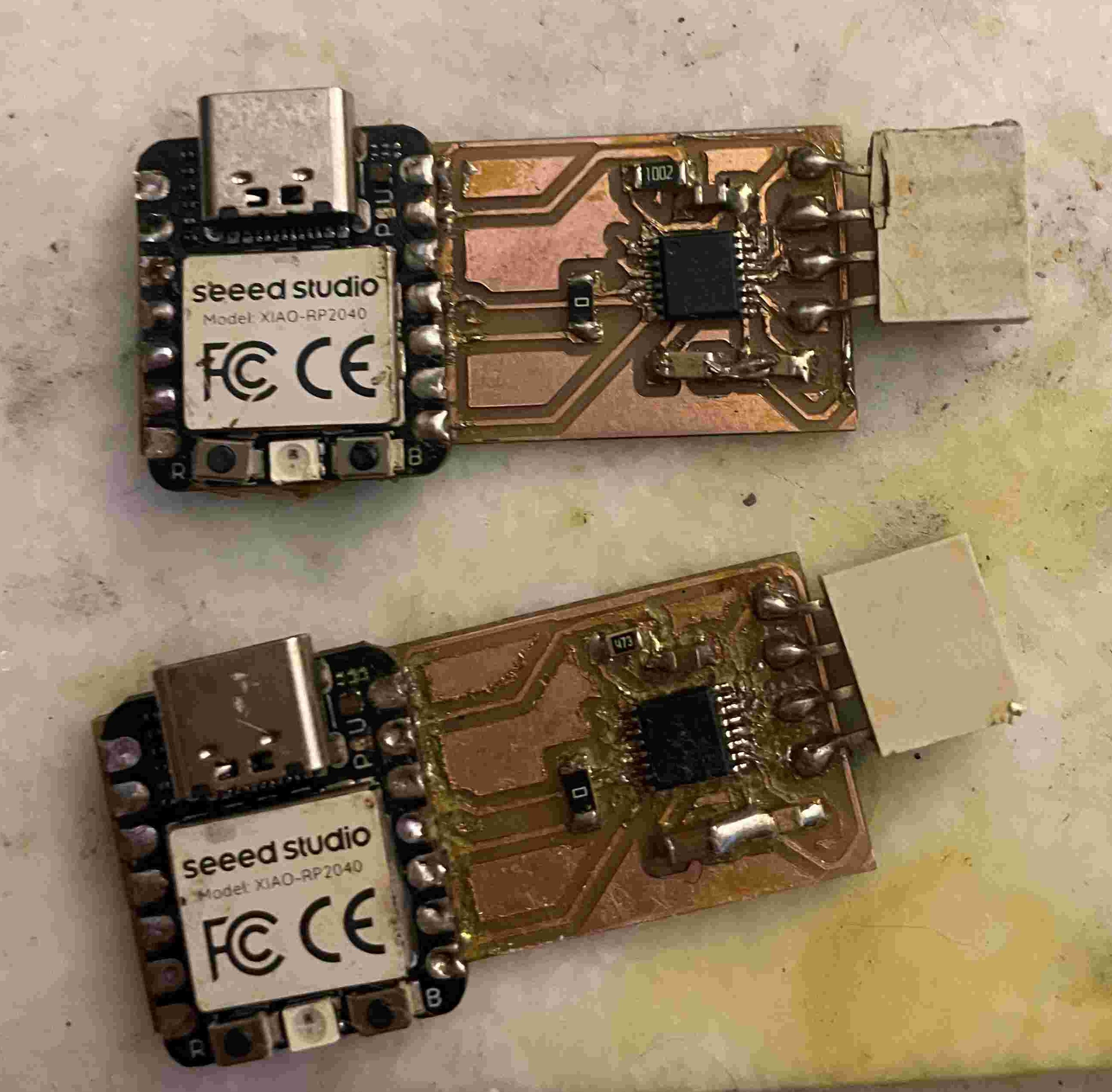
Download the gerber file for version 4 here!
The first two iterations were based on the DRV8833 motor driver - which happened to be the most immediately available motor driver at the lab. After the first two iterations failed to work properly due to some shorting issues and ripped traces, we decided to just go ahead and simplify the design to include only the bare minimum needed for controlling the motor. We ended up replacing the DRV8833 with the DRV8424 in the 3rd and 4th iterations, which is the same driver used on the Urumbot, to hopefully facilitate easier success using an already proven design. Unfortunately, after testing with the DRV8424, the xiao does not seem to supply enough power for the motor to move, and any movement to be very weak and easily obstructed by the touch of a finger.
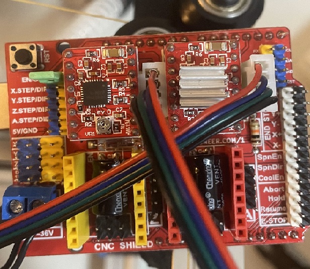
Since we were pressed for time, we ended up using an Arduino using a stepper motor shield, running A4950 motor drivers. This worked well enough for this prototype. Future iterations on this project would ideally include the Xiao-based motor controller, once a proper circuit has been set up.
coding the Core XY
Big thank you to Adam Stone for sharing how he got his code to work with the arduino stepper shield. We then adapted it to work with our coreXY-based machine.
Core xy focuses on a principle of using 2 motors to control the diagonal movement of the head. When working in unison, the additive and subtractive forces of the diagonal pulling of the motors will cause the head to offset in the regular x and y directions. This setup allows us to leave our motors detached from the axis to provide faster acceleration. Read more about core xy here
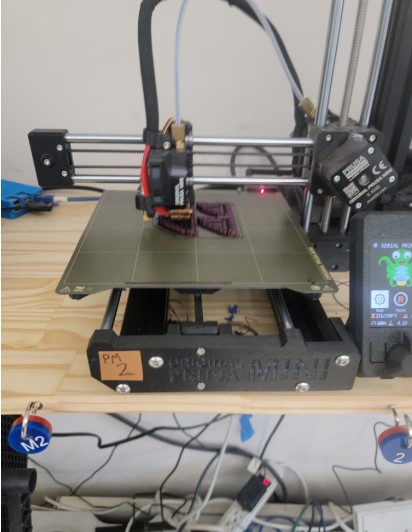
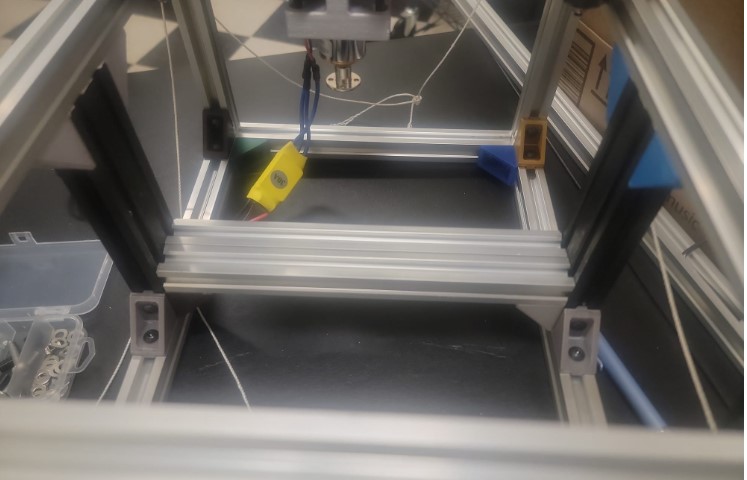
Here is a link to the code used to move the spindle around the bed of the machine: arduinoBufferCode.ino
Here we run a simple script that causes the head to traverse across the build plate, removing any excessive burring on the pcb taped below.
Future improvements
We have a number of areas we can improve in the next iteration:
-
Get our designed electronics working with a single USB connection for both power and comms to streamline cable management
-
Add wight to the base to stabilize the machine
-
Add more cleaning head options and/or easier method for changing tools
-
Add easier control panel to vary the tool path and cleaning head speed