9. Electronics Production
This week our focus was on testing our milling machine.
Zack Budzichowski: Milled test boards
Dan Stone: Documentation
Adam Durrett: Analysis
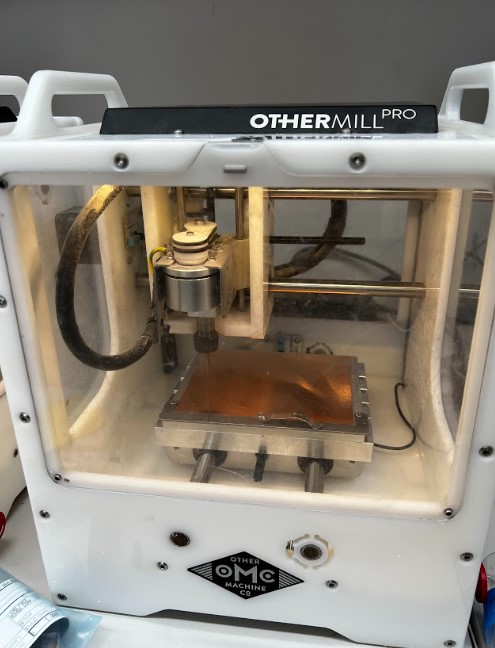
A majority of the milling machines in our lab are the Other Mill Pro. You can find the technical specs here:
In tandem with this, we use Bantam Tools to control our milling machines: https://www.bantamtools.com/software-download
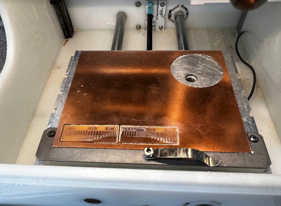
We started by placing our single-sided pcb blank onto the bed of the milling machine. It is secured using Nitto double-sided tape on the bottom, and pressed down to ensure the board lays as flat as possible.
We wanted to test the cutting accuracy and speed of a 1/64” end-mill compared to a 0.005” pcb-engraving bit. We followed our workflow here: https://docs.google.com/document/d/191NHuEW-KKZjmIklXJ3gB3FSlzvCHOjvwVjrvwpfwTU
This involved placing the material, prepping the gerber files on the Bantam Tools software, changing the bit and measuring it, measuring the width of the material, and running the tool paths.
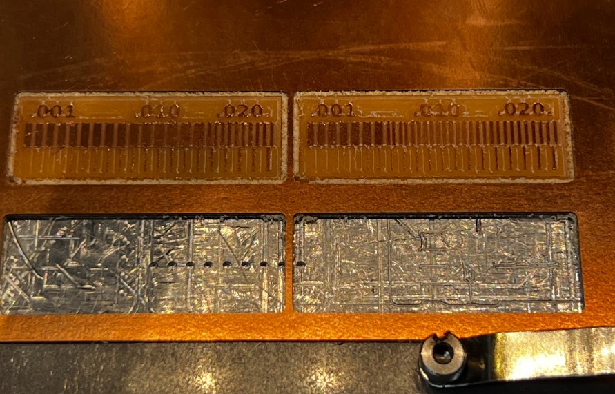
Here are the results of our first two runs:
The one on the left was done by the end-mill, and the right by the pcb-engraving bit.
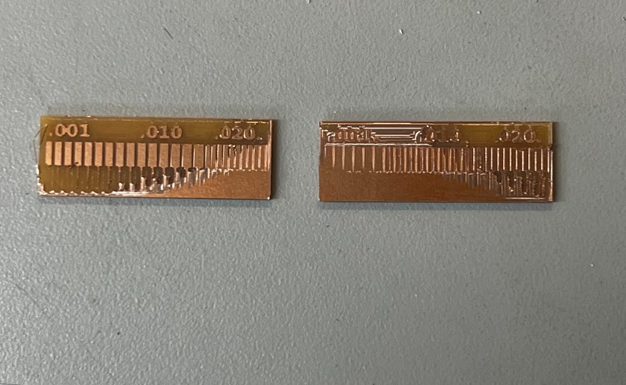
 From this first test, it appears that the board was a bit un-level, and the cut depth was not deep enough. This combination caused the board to not mill properly, in that some traces weren’t fully milled out with tapering from fr1 to copper.
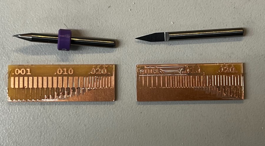
We re-ran the cuts with a deeper cut depth. Again, end-mill on the left, and pcb-engraving bit is on the right.
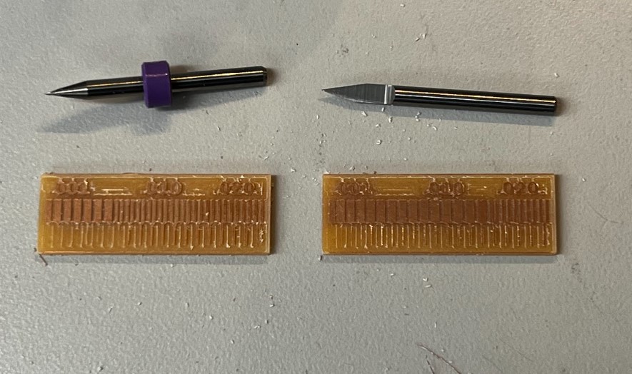 This time we actually got it to cut the traces fairly clean. As expected, the pcb-engraving bit was able to go into higher resolution, with smaller trace widths. The end-mill tore it up when it got too small.