Weeks 12 Students B
David, Dylan, Ginny, Dariyah, Stuart
Requirements:
- Probe an input device’s analog levels and digital signals
Time of Flight Sensor - Stuart, Ginny, Dariyah, Dylan
Measuring
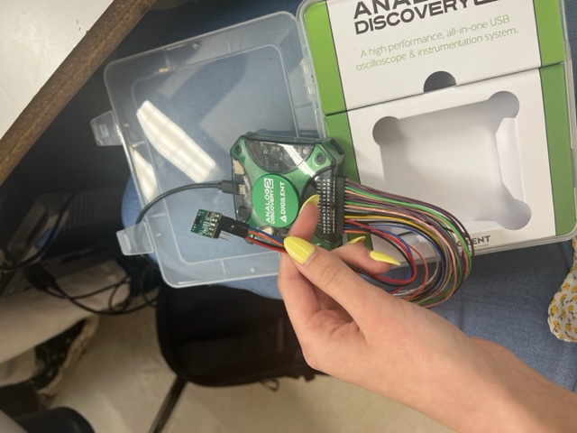
We used a time of flight sensor to probe it’s anaglog and digital signals. The chip was this chip: VL53L1X-SATEL on a PCB1540 breakout board. To see the measurements, we plugged the time of flight sensor (ToF) into the Waveforms Analog Discovery 2 which along with the Waveforms app, allows users to use an osciliscope to measure a varity of things from an input device. We connected the SDA pin to the 1+ pin on the Analog Discovery, the SCL pin to the 2+ pin, the VDD pin to the V+, and the GND pin to the GND pin.
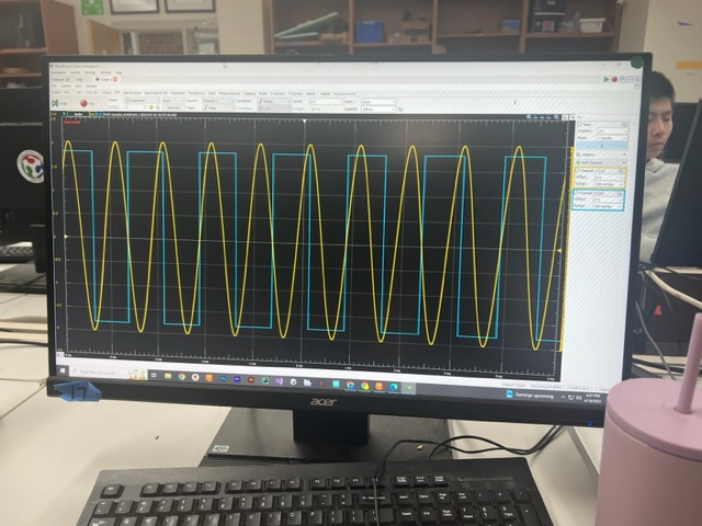
 We then plugged in the Analog Disovery into a computer and opened the waveforms app. Inside the Waveforms app we opened a new workspace for a scope and then ran the oscilicope and on screen the analog and digital signals began appearing. The digital signal is in blue and the analog signal is in yellow. Both have consistant amplitudes.
Accelerometer - David
Mistake
I accidentally broke the board that I milled for the accelerometer, because the female pins that were vertically soldered onto the board weren’t very stable. So, I have to conduct the test using a breadboard.
Wiring
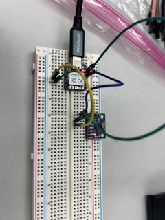
First, I wired the schematic of the accelerometer by itself with the RP2040 Xiao board to make sure that the program is working:
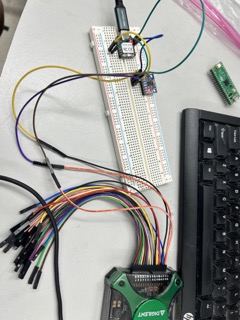
Then, I connected this part with an Analog2Discovery machine. I connected positive pin on Channel 1 to the SCL pin, and the negative pin on Channel 1 and the general negative pin to the ground.
The power pin on the Analog is not connected as the accelerometer is already being powered by the computer.
Here is the complete wiring:
Results
I didn’t have any trouble capturing the results of the data on Waveform. First, I booted up the Waveform software and went to the Scope tab. I didn’t need to set a voltage in the supplies tab because the accelerometer was already being powered by the Xiao.
Next, I clicked run, and changed the rate settings to 100MHz in order to display the graph more smoothly.
Here is the result for the SCL pin:
Here is the SDA pin:
In the videos, I have also included a frequency measurement. It looks like the SCL pin’s frequency hovers around 330000 Hz, which is close to the frequency in the Thonny code at 400,000 Hz.
You can also see that the peaks are not evenly distributed and flashes in and out of sight. This is due to the large amount of noise in the connection, as the I2C communication system is not very practical. This phenomenon could especially be seen in the SDA pin, since data is transmitted through this line. As a result, the data makes the frequency more volatile.