Weeks 10 Students A
Jed, Merrit, Ryan, Griffin, and Adam
Theory - Griffin, Ryan
Our group decided to measure the power consumption of a NEMA stepper motor. First, Griffin figured out how to wire it with the motor driver.
Ryan did research on how the stepper motors work. In a simplified explanation, stepper motors require motor drivers, in which there are four pins connected to the motor driver being controlled either by a microcontroller or some kind of signal. These four signals can be controlled or coded to then control a set of electronic switches, most often transistors. A common method of this is the H-Bridge, a setup of four transistors in the shape of the H. Ultimately, the sequence and power applied the transistors, effecting the coils inside the Stepper motor effects the speed and direction of how it turns. This works because of how the inner motor gear is magnefied, alternating between positive and negative poles for each tooth.
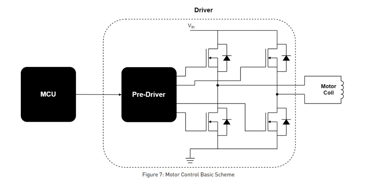
Here is a simple wiring image of the inside of the motor driver.
From this website, we were able to learn that the signal can be controlled in certain ways such as
- Step/Direction – By sending a pulse on the Step pin, the driver changes its output such that the motor will perform a step, the direction of which is determined by the level on the Direction pin.
- Phase/Enable – For each stator winding phase, Phase determines the current direction and triggers Enable if the phase is energized.
- PWM – Directly controls the gate signals of the low-side and high-side FETs.
The rotors, or the setup of the magnets also differ. There are many types, but our motor driver controleld via power, ground, and four pins. The pins then send the current, effecting the current of the coils, therefore creating a magnetic field and adjust the rotor accordingly to make the stepper motor turn in specific angles and directions and speeds.
The voltage and current supplied to the motor driver may also effect the outcome. To measure the power consumption of our stepper motor, we used a Wamptek DC power supply.
Measuring Power Consumption - Merritt, Jed, Adam
We hooked up a power supply to a stepper motor and slowly increased the voltage (not touching the current), and read the power consumption. Here is a video of the process.
Graphing & Analysis - Adam
Here is a link to the Desmos project
I moved the datapoints into a line graph using Desmos.

The first flat part of the graph indicates that the motor won’t run unless there’s a minimum voltage (observed threshold = 3.97V) and then there was a sharp increase in power, after which the trend became fairly linear with a strong correlation.