Week 5 Students B
Project members: Dariyah Strachan, Dylan Ferro, Ginny Foster, and Stuart Christhilf did the datasheet examination. David Tian, did the oscilloscope work.
Our Chip is the AtTiny 1614, here is the datasheet
Describing ATTiny 1614
| Microcontroller | ATTiny1614 |
|---|---|
| From Datasheet | |
| Architecture | TinyAVR |
| Operating System | N/A |
| number of Cores | 1 |
| Core Clock speed | 20 MHz |
| number of Registers | 4 |
| Register Size (8/16/32/64) | 8 |
| SRAM | 2 KB |
| Flash | 16 KB |
| EEPROM | 256 bytes |
| Compatible Programming Languages | UPDI |
| Programming Interface | arduino, C, C++ |
| Programming Workflow | ”“”Sequence for Execution of Self-Programming In order to execute self-programming (the execution of writes to the NVM controller’s command register), the following steps are required: 1. The software temporarily enables self-programming by writing the SPM signature to the CCP register (CPU.CCP). 2. Within four instructions, the software must execute the appropriate instruction. The protected change is immediately disabled if the CPU performs accesses to the Flash, NVMCTRL, or EEPROM, or if the SLEEP instruction is executed. Once the correct signature is written by the CPU, interrupts will be ignored for the duration of the configuration change enable period. Any interrupt request (including non-maskable interrupts) during the CCP period will set the corresponding Interrupt flag as normal, and the request is kept pending. After the CCP period is completed, any pending interrupts are executed according to their level and priority”“” |
| Block Diagram (image) | 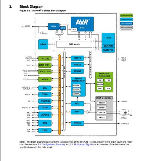 |
| number of I/O Pins | 22 |
| ADC/DAC (how many bits??) | 2 |
| PWM | 16 bit single and dual slope |
| Operating Voltage Range | 0.55V • 1.1V • 1.5V • 2.5V • 4.3V |
| Power Consumption | 200 mA |
| Built-in Features | CIPs, capacitive touch, PTC, |
| Oscilloscope Tests | |
| Flip-Bit Speed Test Frequency | 380.52kHz |
Oscilloscope testing
For this part of the group project, David Tian did the Flip-Bit Speed Test Frequency test for the oscilloscope.
An oscilloscope is basically a type of electronic test instrument that graphically displays varying electrical voltages. Our board is the ATtiny1614, a microcontroller, and so David tested the pin 2 on the Attiny 1614.
At first, he didn’t know what to do, and struggled to download waveform on his laptop. He went to their website and filled out the registration form, but it kept asking him to wait. Later, (maybe under a better internet situation), the software downloaded. Waveform is basically a software that allows you to test the voltage between 2 points in a circuit.
Side note
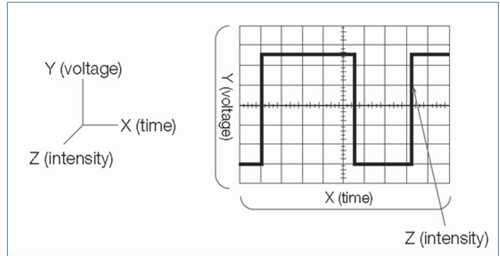
There are also different types of waves that an oscilloscope can detect. Here is an image representing some of them:
Analog 2 Discovery
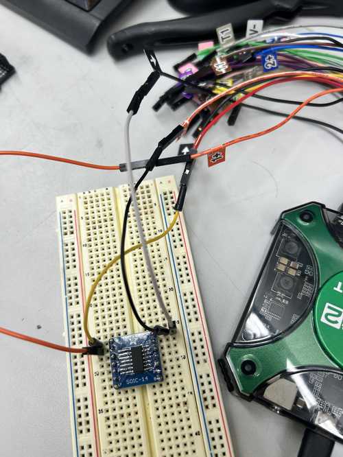
He set up the Analog 2 Discovery machine to the computer, and plugged some random wires into the Attiny, but as expected, it didn’t work.
Then, fellow student Adam Durrett showed him how to connect the wires to test pin 2. The +1 pin has to connect to pin 2 and the -1 pin is connected to the ground on the Attiny. This ensures that we keep to channel 1 (the different channels in the software makes it easier to differentiate between different pins/systems).
Then, the power is connected to the attiny’s power pin, and the ground of the attiny is connected to the ground of the analog machine.
When we clicked run, nothing happened, so then we checked whether the master enable was on → it was not. So, we clicked it to turn it on and set the voltage to 4 volts.
After clicking run, it worked. Then, we went to measurements → add measurements → horizontal to get the exact frequency of the graph. You can see that it goes from 4 volts and drops to 0 volts. The Hz count is how long it takes for the electronic component to refresh/update, the higher the better.
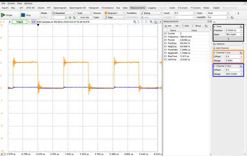
We got a test frequency of around 380 kHz. We didn’t do a temperature test for the attiny due to the lack of a thermometer.