Week 7 Students B
Project members: Dariyah Strachan, Dylan Ferro, Ginny Foster, Stuart Christhilf, and David Tian
Oscilloscope-Analog: David, Stuart, and Dylan
David, Stuart, and Dylan worked on the first part of testing the LED pin on the oscilloscope.
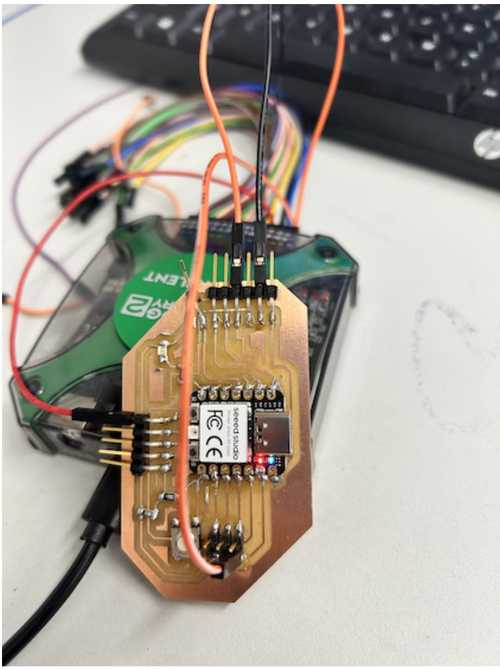
Dylan copied a code segment online to program the Seeed Studio that we soldered, and it made the LED blink and fade: the code is stored in examples → basic → fade.
We got our Analog 2 Discovery and started the Waveform software. Then, since we are using Channel 1, David plugged the ground of the Analog machine to the ground on the Seeed board, the power to the power of the Seeed board, and the channel +1 pin to the LED pin, and the channel -1 pin to another ground pin.
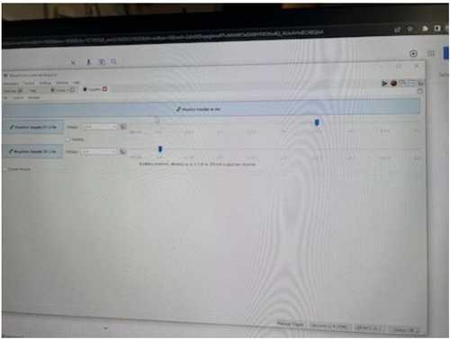
However, when we uploaded the code and started Waveform, it didn’t work. To start the waveform software, Stuart went to the voltage supply tab and changed the voltage to around 3.5 volts for the channel +1 pin, and -0.5 volts for the channel -1 pin.
Then, we went to the scope tab, and clicked run. Nothing happened.
Then, Dylan came up with a creative solution. He changed the pin number in the code to the D1 pin, or pin 26, of the studio, and pretended that that pin was the LED. So, the output signal of that pin would supposedly turn the LED on and off.
The interesting thing was, I plugged the channel 1- pin into the bottom row of the pins. Dylan, on the other hand, plugged the pin on the right for the ground. So, then, I am assuming that the ground pin on the right side is specifically designated for the ground of the LED, and not the ground of the analog machine.
We uploaded the new code, and sure enough, the analog machine produced our wave. We see that there is some static, but not too much. The sine wave was produced to test that pin.
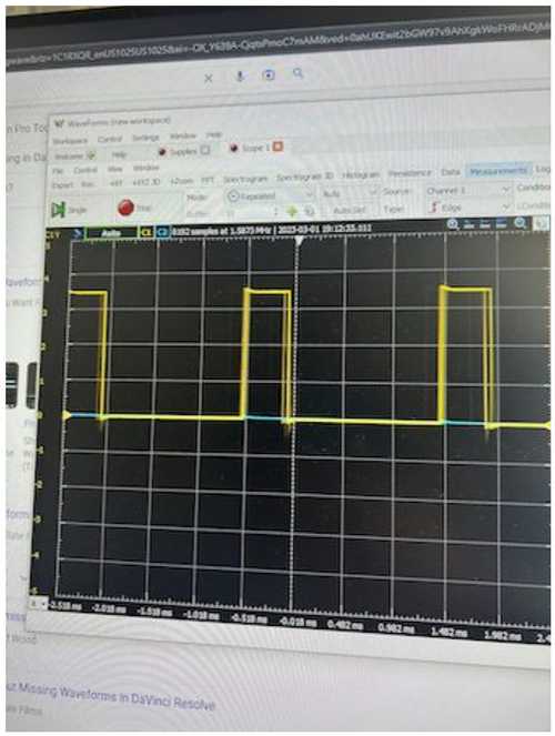
Then, we went to the measurements tab, and added the channel 1 voltage difference, hertz, and wave peak and trough tabs, and saw the exact measurements.
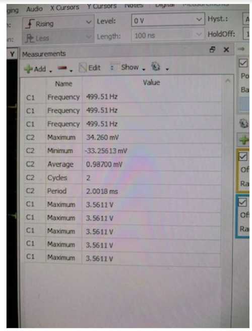
So, as you can see, the frequency is around 500 Hz for that pin.
Max Voltage test: Ginny and Dariyah
For the Max voltage test, we took our circuit and connected the power to one of the header pins in the set at the bottom of the circuit. Then we connected ground and 1- to the 2x3 header pins on the left with the 1- wire going to pin 9 of the SEEED. After that, we connected 1+ on the right to pin 0, and we saw two parallel looking waves displayed on the screen, which signaled to us it was working. Because Dylan, Stuart, and David had just done their test, we did not have to start and set up waveforms, we only had to connect everything and hit run. Next, we looked at the data displayed on the right measurements colum and we saw a number that was constantly changing between 3.5 and 3.6 maxium volts, this told us the max voltage the circuit could take. From there we looked to see the highest spike in the values was (3.6V) and took that to be the max voltage the circuit could handle.


Multimeter: Dylan
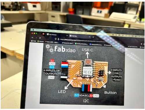
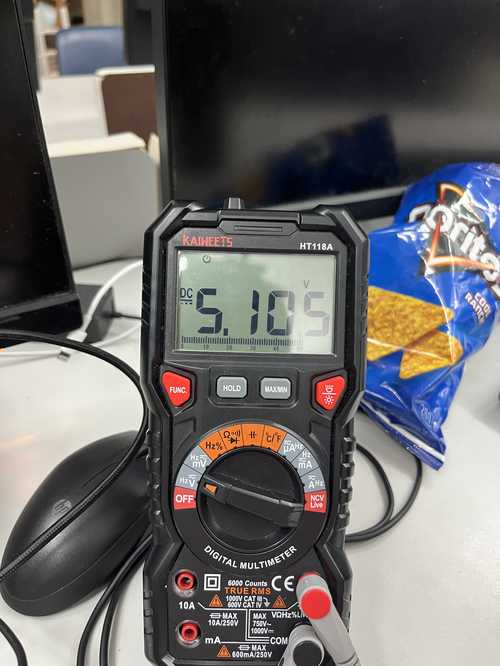
To measure the FabXIAO rp2040 I used a multimeter. I connected the power cord to the 5V output and the ground and got a measurement of 5.105V
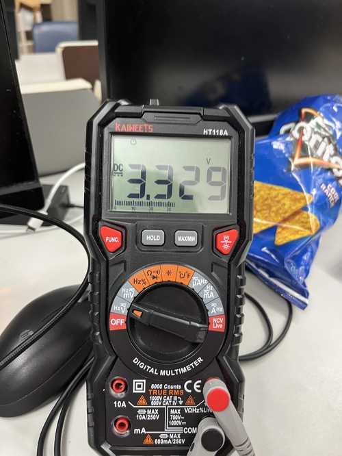
Then I moved the power cord to the 3.3V port and measured 3.329V
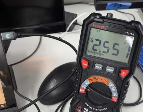
Finally I uploaded the Blink code from the arduino examples and measured the led as it blinked. When low, it measured 0V and when High it measured 2.551V.