Week 5 Students A
Overview And Findings
This week, all three groups in our lab took one microprocessor and collected information about it. We then compared the information surrounding the architectures of different chips. Here is all of our collected data for the RP2040, ATtiny1614, and ESP32-S2!
Data Collection Documentation
The data collection was split between everybody except Merritt, who worked on the AnalogDiscovery to find the bit flip speed test. To speed up the process, most of the details could be found on ChatGPT, which navigated which sections we could find information for each aspect of the RP2040. Also, the more we looked at different types of datasheets, the more we realized that their length is not intimidating. Simply go through the table of contents, and everything is extremely well organized. This knowledge of datasheets can be used later if we want to research the best controllers to use for our final projects.
Programming Workflow
Prompt For ChatGPT
write a "programming workflow" for an rp2040 microcontroller
Response
Sure, here's a programming workflow for an RP2040 microcontroller:

1. Set up your development environment: Before you can start programming the RP2040 microcontroller, you'll need to set up your development environment. This will involve installing the necessary software and tools on your computer. You can use either the official Raspberry Pi Pico C/C++ SDK or other third-party toolchains such as the ARM GCC toolchain. You'll also need to download and install a code editor or an Integrated Development Environment (IDE) like Visual Studio Code, Eclipse or Keil.

2. Create a new project: Once your development environment is set up, create a new project for your RP2040 microcontroller. In this project, you'll be able to write, compile, and test your code.

3. Write your code: Start writing your code using C or C++. The RP2040 microcontroller supports these programming languages, and you can use any text editor or IDE to write your code. You will have to interact with peripherals such as GPIO, I2C, SPI, UART, and timers, among others. You can use the RP2040's SDK and its libraries to make the development process easier.

4. Compile your code: After you've written your code, compile it using the tools you installed earlier. Make sure that you've included all the necessary header files and libraries in your code.

5. Flash your code: Once your code is compiled, it needs to be uploaded to the RP2040 microcontroller. You can use a programming tool, such as a Raspberry Pi Pico, or a USB-to-UART converter to upload the code to the microcontroller's flash memory.

6. Test your code: After you've uploaded your code to the RP2040 microcontroller, you can test it to make sure it's working correctly. You can use a debugger or a serial console to view the output from the microcontroller and debug any issues.

7. Iterate: Once you've tested your code, you may need to make changes and repeat the previous steps until your code is working as expected.

8. Refactor: As your code base grows, it may be necessary to refactor your code to make it more maintainable and scalable.

9. Document: Document your code and development process, so that it's easy to understand and maintain.

10. Release: Once your code is tested, working correctly, and well-documented, you can release it to production. This could involve manufacturing custom hardware or integrating the RP2040 microcontroller into an existing system.
I read over the workflow to make sure that it was accurate, and the only detail I added was that development for the RP2040 chip can also be done in MicroPython with an IDE such as Thonny. I also removed steps 7-10 since they aren’t essential to programming the chip. Here is the final programming workflow:
1. Set up your development environment: Before you can start programming the RP2040 microcontroller, you'll need to set up your development environment. This will involve installing the necessary software and tools on your computer. You can use either the official Raspberry Pi Pico C/C++ SDK or other third-party toolchains such as the ARM GCC toolchain. You'll also need to download and install a code editor or an Integrated Development Environment (IDE) like Visual Studio Code, Eclipse, Keil, or Thonny.
2. Create a new project: Once your development environment is set up, create a new project for your RP2040 microcontroller. In this project, you'll be able to write, compile, and test your code.
3. Write your code: Start writing your code using C, C++, or MicroPython. The RP2040 microcontroller supports these programming languages, and you can use any text editor or IDE to write your code. You will have to interact with peripherals such as GPIO, I2C, SPI, UART, and timers, among others. You can use the RP2040's SDK and its libraries to make the development process easier.
4. Compile your code: After you've written your code, compile it using the tools you installed earlier. Make sure that you've included all the necessary header files and libraries in your code.
5. Flash your code: Once your code is compiled, it needs to be uploaded to the RP2040 microcontroller. You can use a programming tool, such as a Raspberry Pi Pico, or a USB-to-UART converter to upload the code to the microcontroller's flash memory.
6. Test your code: After you've uploaded your code to the RP2040 microcontroller, you can test it to make sure it's working correctly. You can use a debugger or a serial console to view the output from the microcontroller and debug any issues.
Comparing The microcontrollers
Flip Bit Speed Test
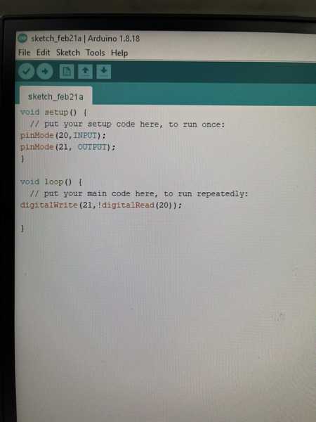
To compare the speed of our microcontroller, we performed the Flip Bit Speed test. The flip bit speed test involves wiring 2 IO pins together, and then writing a statement that makes it so the pins are always opposite one another and then turning one pin High. This test changes the voltages of the 2 pins very rapidly, and is a way to test the processing power of a microcontroller. With the help of Adam Durrete, I wrote the following code:
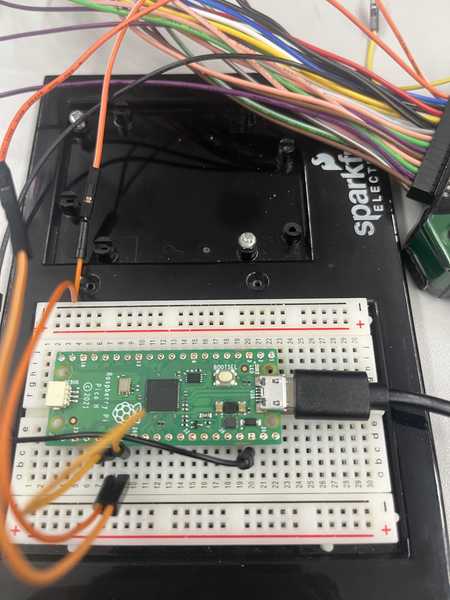
Next, I wired pins 20 and 21 to eachother, wired the osciloscope plus and minus pins to each pin, and wired the ground pin to the ground pin on the pico
Here’s what the waves looked like on the osiloscope, as well as information about the frequency that the pits were switching at.
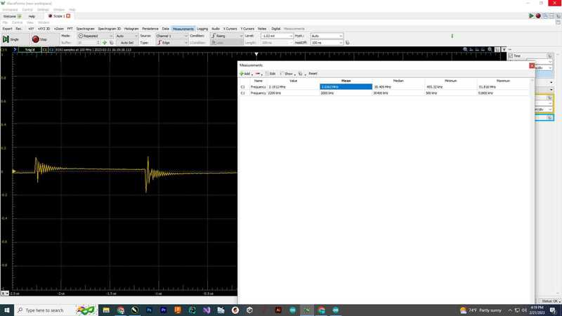
I ran the test for a little and then found the average to be around 4Mhz, I put this into our group documentation.
Bit flip test with temperature reader
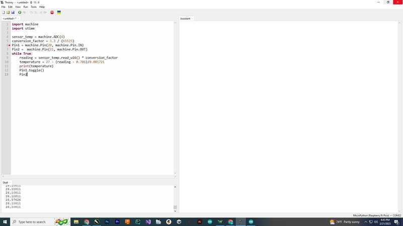
In our spreadsheet, I realized that there was also a box labled temperature, as we were supposed to find the temperature of the microcontroller during the test. I looked around at the doccumentation for the sensor and found that it would be much easier to do this in micropython. I used This tutorial for code that would print out the values from the temperature sensor. I then used Python’s built-in Toggle Function to switch the 2 bits. The final code looked like this
Finally, I took an average of these temperature values, and put them into our sheet.