12. Input devices
Zack Budzichowski: Analysis, documentation and pictures Dan Stone: Sensor set up and coding, documentation Adam Durrett: oscilloscope operations, analysis,documentation
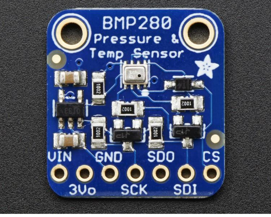
Adafruit BMP280 I2C or SPI Barometric Pressure & Altitude Sensor
For our group work we decided to use the Adafruit BMP280 Barometric Pressure + Temperature Sensor.
You can find the data sheet here
In the data sheet there is a clear pint out
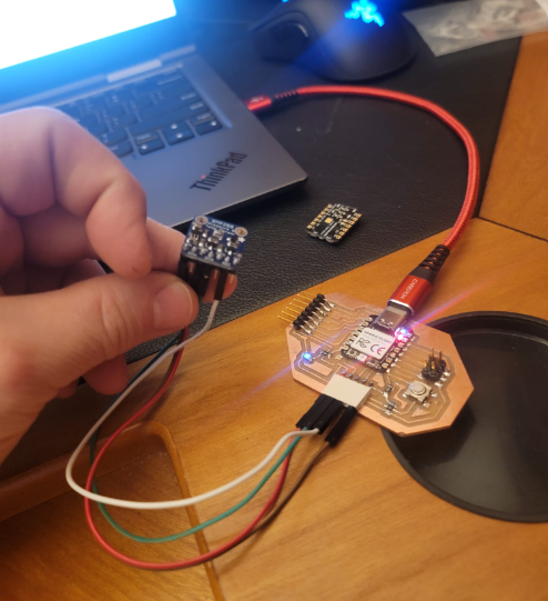
We hooked the sensor up the Fab Xiao and the Oscilloscope
The pinout for the board is
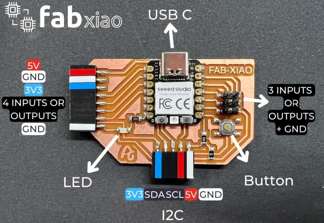
We hooked up the sensor
This week we took a look at the SCL and SDA lines of an external I2C device connected to the rp2040. Theoretically, we should get two alternating DC signals: - SDA: A square wave with dips to represent 0s in the data line - SCL: A constant timer with 50% duty-cycle,
Code for BMP280 I2C Sensor
// the setup function runs once when you press reset or power the board
void setup() {
  Serial.begin(9600);
  while ( !Serial ) delay(100);   // wait for native usb
  Serial.println(F("BMP280 Sensor event test"));

  unsigned status;
  //status = bmp.begin(BMP280_ADDRESS_ALT, BMP280_CHIPID);
  status = bmp.begin();
  if (!status) {
    Serial.println(F("Could not find a valid BMP280 sensor, check wiring or "
                      "try a different address!"));
    Serial.print("SensorID was: 0x"); Serial.println(bmp.sensorID(),16);
    Serial.print("        ID of 0xFF probably means a bad address, a BMP 180 or BMP 085\n");
    Serial.print("   ID of 0x56-0x58 represents a BMP 280,\n");
    Serial.print("        ID of 0x60 represents a BME 280.\n");
    Serial.print("        ID of 0x61 represents a BME 680.\n");
    while (1) delay(10);
  }

  /* Default settings from datasheet. */
  bmp.setSampling(Adafruit_BMP280::MODE_NORMAL,     /* Operating Mode. */
                  Adafruit_BMP280::SAMPLING_X2,     /* Temp. oversampling */
                  Adafruit_BMP280::SAMPLING_X16,    /* Pressure oversampling */
                  Adafruit_BMP280::FILTER_X16,      /* Filtering. */
                  Adafruit_BMP280::STANDBY_MS_500); /* Standby time. */

  bmp_temp->printSensorDetails();
}

void loop() {
  sensors_event_t temp_event, pressure_event;
  bmp_temp->getEvent(&temp_event);
  bmp_pressure->getEvent(&pressure_event);

  Serial.print(F("Temperature = "));
  Serial.print(temp_event.temperature);
  Serial.println(" *C");

  Serial.print(F("Pressure = "));
  Serial.print(pressure_event.pressure);
  Serial.println(" hPa");

  Serial.println();
  delay(2000);
}
SDA ( Serial Data )
When first connecting to the SDA line, we were getting a constant 3.3v from the SDA pin. This is not what we were expecting, as an I2C data signal should consist of pulse waves of varying widths to represent combinations of 1s and 0s.
After increasing the sampling rate of the oscilloscope from 10Mhz to 33.3 MHz, we could clearly see the PWM signal.
Note that the tops of these waves are a bit wavy, as it does not output a clean DC signal. Small amounts of noise from the environment, other components and potential accuracy of the oscilloscope all have impacts on the resulting waveform.
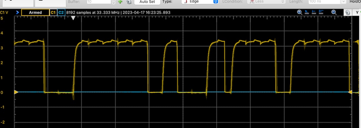
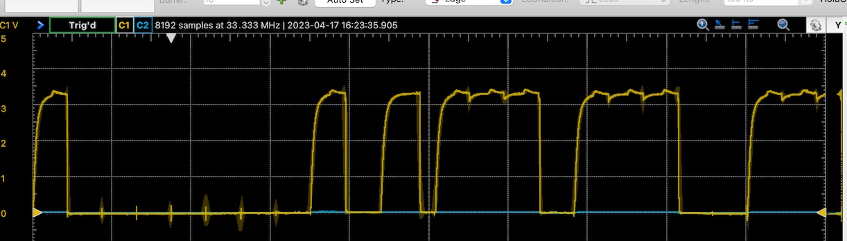 You can see that waves are consistently distributed at a constant frequency. Small dips and peaks that are consistent on the tops of the wave can help point out the individual bits being represented on the serial line.
This data consists of temperature and pressure data picked up by Dan’s sensor.
You can see that waves are consistently distributed at a constant frequency. Small dips and peaks that are consistent on the tops of the wave can help point out the individual bits being represented on the serial line.
This data consists of temperature and pressure data picked up by Dan’s sensor.
SCL ( Serial Clock )
For the serial clock, we expect to see a 50% up time square wave. This is to provide consistent timing of up-ticks and low-ticks at a constant frequency. The I2C device uses this timing to help communicate the data on the SDA line to the microcontroller. Even timing allows for precise bits to be sent.
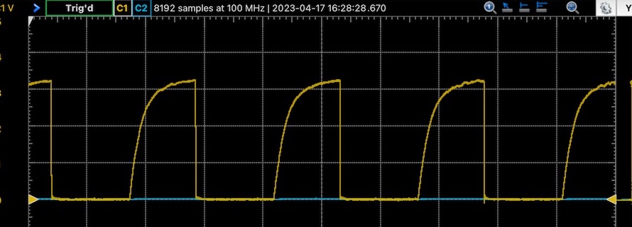 This waveform has a bit of a logarithmic peak. This could be due to a capacitor charging slow in comparison to the output frequency. Each “on” section is the same width as each “off” section, therefore denoting the ~50% duty cycle.