Weeks 8 & 9 Students A
Jed, Merrit, Ryan, Griffin, and Adam
Week 8
Materials - Adam
Last year’s Group B’s documentation helped us learn about different materials for the milling machine, as well as this site.
Materials CNC machines can mill:
- machinable wax
- polyurethane boards
- foam
- metals
- medium density fiberboard
- plastics
IPR = inches per revolution
First pass (roughing cut) feed rate ~ 0.005-0.020 IPR
Second pass (finishing cut) feed rate ~ 0.002-0.004 IPR
Speed and feed rates also depend on the material.
Testing and Milling - Ryan and Griffin
We decided to test how well the Bantam Tools Desktop would work. Griffin found this testing design online, where we could see how well the trace clearance would go. We could test out any bit for this, but we knew it was pretty obvious that the 1/32 inch would not do well for this job. Therefore, we decided to test the 1/64 inch bit on the milling machine. Once Griffin took the iamge and prepared the design, we opened it on the local computer and into the Bantam Tools software.
Since Ryan had cut his own board before during Design week, he was able to follow through the process. First, we followed the work flow and put NItto tape on the back, spreading it out so we knew it was secure. We palced it and and pressed it for secuirty. Griffin brought in the design. We noticed that for some reason, the bottom line of the profile didn’t come in, so we had to guess and check with the offsett until the cut was lined up with the bottom, and we didn’t miss any of the traces, which was important for the testing.
Ryan set up the bit with the help of Griffin to get the bit in with the wrenches. Once we had the bit in, Ryan set up the tool by probing it off the bed. Once the bit was probed, we set the thickenss of the material by attaching the metal probing clip, and getting the thickness of the FR1 material board. Once we made sure the bits were set and there were on errors, we began the milling process. Luckily, the milling process went quite smoothly. We cut the outline with a 1/32 inch, and used the vacuum to clean it up.
We observed the board, and we noticed the smallest trace(.001 inch) was not quite visible. There was some form of a mark, but the copper was not much visible. This was interesting because the group 2 years prior taking Fab Academy had milled it with the Othermill tool, and their smallest trace had bee visible. We noted this for the Bantam Desktop Software. Here are the images of the outomce:
 Photo by Jed
Git - Adam
When creating a branch locally instead of on the Web IDE, use the following commands to create a branch. I learned about the set-upstream command when git suggested it before pushing changes to an un-pushed branch.
git checkout -b my-branch-name
git push --set-upstream origin my-branch-name
Week 9
Due to Spring Break, we fell behind on the group work, so we used the same branch to document our group work for Machining and Electronics Production Week.
Definitons of Terms - Merritt
This week, I was tasked with defining some terms from the milling process, as well as going over the speeds and feeds charts for our machines.
Cutting Definitions
I found this formula sheet which was really helpful as at contained all the equations and descriptions of the variables. Here’s a list of these variables and some descriptions for the less obvious ones: Speed (Surface Feet per Minute)
SFM- A derived unit for the speed of the cutting tool. to calculate SFM. Take the RPM of the machinePIDiameter of the cutting tool/12”. Feed (Inches per Minute)
IPM - This is the feed rate of the tool,or how many inches the tool moves per minute.
Feed per Tooth FPT- This is the feed per tooth, or the amount of material that is removed by each tooth/flute per revolution of the cutting tool. Feed per Revolution FPR- The distance that the cutting tool travels during one revolution of the spindle.
Depth of Cut DOC
Width of Cut WOC
Tool Diameter D
of Teeth in Cutter Z - this is the same as the number of flutes in the cutter
Material Removal Rate (Cubic Inches per Minute) MRR
Calculations
Most of the calculations are already outlined in the PDF sheet, however, I want to focus on Chip Load. Chip load is the size or thickness of the chip that is removed with each flute per revolution of the machine. This is important to calculate setups for the machine to get a good surface finish while extending the longevity of the tool. Chip Load = Feed Rate (inches per minute) / (RPM x number of flutes). The chipload calculator is built in to shopbot, so you can also calculate through there.
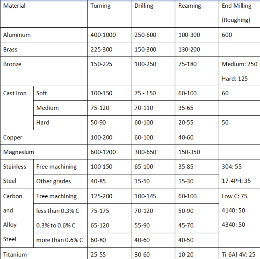
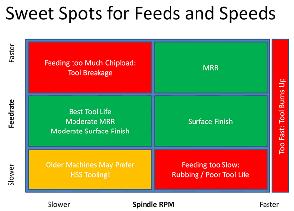
Speeds and feeds
Speeds and feeds describe the relationship between the speed of the spindle and the rate that the machine moves. Here’s a chart that shows how some of these relationships work.
The feeds and speeds guides for shopbot can be found here
Toolpath Test - Jed and Griffin
Toolpath Test files.
When machining the 2 main cuts we use are profile and pocket. Profile runs the outlie of cut, while pocket is everything inside the line of your cut. Once you selected your vector in Aspire and selected your cut you can select toolpath, your options are Outside, On, and Inside. This refers to the toolpath and where it is on your vector you selected. So outside the line of your vector, on the line of your vector, or inside the line of your vector. To show the diffrence, we created a simple file that would cut out a square that we copied and pasted to make sure is was the same size. We then gave each square a different toolpath. For each cut we only set the cut depth to around .166 inches because we didn’t want to cut all the way through the wood and the wood depth was .464 inches. Here is a photo of the product of the cut, from left to right, Outside, On, Inside:
 Photo by Jed
Runout Test - Adam, Ryan, Merritt
We learned about how the bits on the CNC machine can be a bit inaccurate due to runout, which we learend was how off the bit was to the center alignment of the rotational axis. To test this, we learend that we could use a certain runout tool which we press a thin line against the bit and spin it with our hands, and we see how much it moves when you spin it. We first used the Shopbot software to jog the machine up so we could have space to touch the line of the tool against the bit. We carefully with eye protection and making sure our hanbds were clear from the bottom, we spinned the bit with our hands to measure the runout.
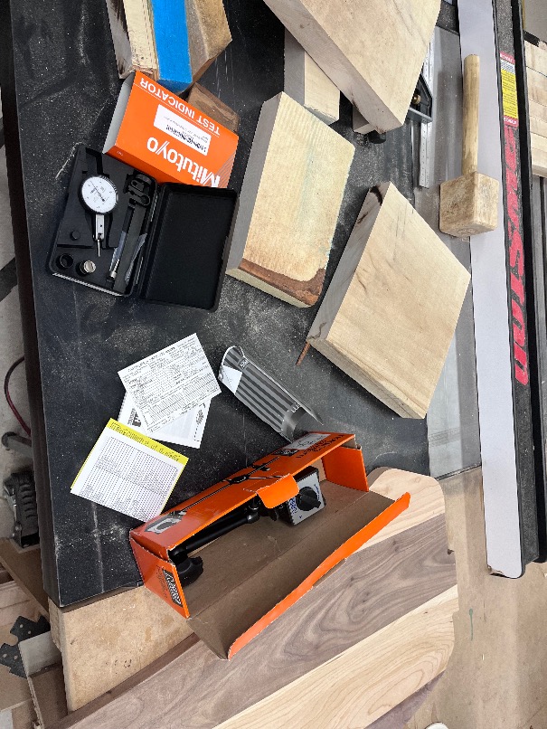 Our tools for the runout test
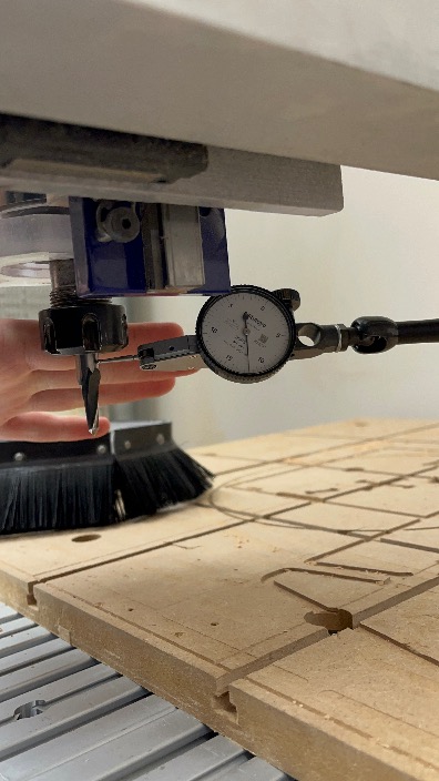 Perfroming the test