8b. Computer controlled machining (CLS Adults)
Our group assignment this week is as follows,
group assignment do your lab’s safety training test runout, alignment, fixturing, speeds, feeds, materials, and toolpaths for your machine
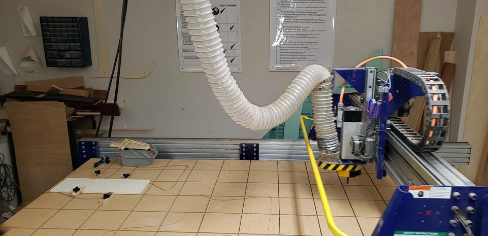
For these parameters, our team will be characterizing the labs’ Shopbot Alpha.
| Parameter | Characterization Method |
|---|---|
| Runout | Runout indicator |
| Alignment | L-shape alignment tool |
| Fixturing | Picture of fixturing options |
| Speeds/Feeds | Writeup |
| Materials | Writeup |
| Toolpaths | Cut one object with inner, outer, and on selected |
The writeups in this weeks section were adapted from our labs’ engineering curriculum and labs ‘CNC bible’ below,
Additionally, here is the manual for our Shopbot Alpha.
And lastly, our workflow for the Shopbot Alpha.
In addition to being provided these materials, our team underwent an extensive lecture and safety training from Tom Dubick for using the Shopbot Alpha.
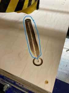
Runout
Spindle Runout, or Tool Runout, as it can also be called, is the inaccuracies that cause a tool (in a mill) or workpiece (in a lathe) to spin off the ideal axis.
For runout, our team used two different dial indicators to qualify the spindle runout. The Mituoyo indicator measures increments of 0.0005” whereas the Starrett measures increments of 0.001”, usually called “1 thou”. The mag base was able to attach to the machine frame and position the indicators. For this test, we decided to remove the key from the machine so that the spindle could not turn. Instead, we simply rotated the spindle by hand to test the runout, as is commonly done in industry.
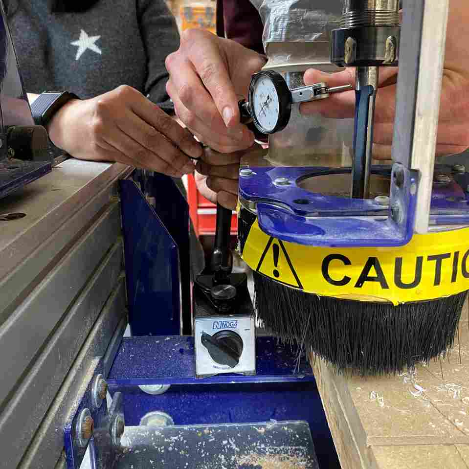
We positioned the Mituoyo indicator on the precision shank of the 1/2” tool, above the flutes. By rotating the spindle by hand, we could tell the circular deviation of the tool and therefore spindle. Too our surprise, the spindle was “running true” within +/- 0.0005”.
Since these first results were more precise than our team anticipated, we decided to verify the results with the Starrett indicator. This second test yielded similarly great results and was “running true” within 0.001”. Very impressive.
Alignment
In this case, Alignment refers to the alignment of the X and Y axis compared to theoretically perfect (global) and the machine bed (relative).
For alignment, our team decided that it would be most useful to qualify the axis’ of the machine relative to the T-tracks in the spoil board, since these tracks will be used for fixturing our materials. Theoretically, these tracks should be perfectly alligned to the spindle, since it was the spindle which created them. The following test will verify that assumption and ensure that the axis’ are still running “true”.
We will line up a piece of wooden stock to the T-tracks and create the following L-shaped part from it.
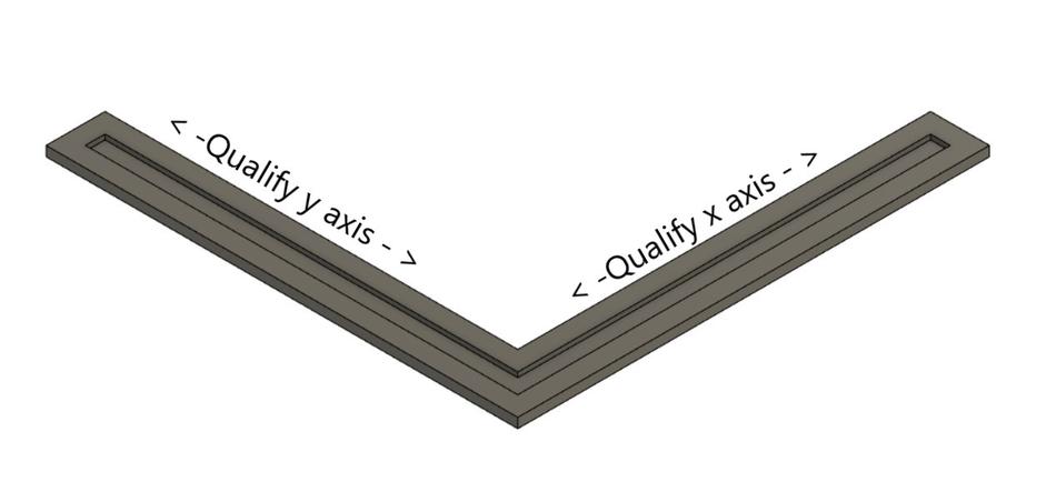
We can compare the features of this finished part relative to the tracks it was fixtured with, to check the alignment relative to the machine bed.
What this test will not immediately tell us is how close the axis’ are to theoretical perfect alignment. For this,we can check the objective squareness of this part. Comparing squareness precisely will be challenging, but we can atleast see if there are major problems.
Fixturing
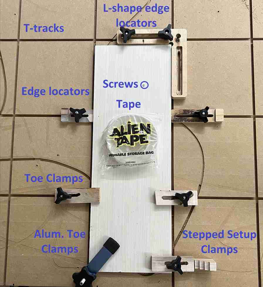
Fixturing is the process of holding down your material while cutting. Choosing the right hold down method can be challenging, but it is an important part of project planning. Not only does the workpiece need to be held securely, but it is important to know what will happen to parts as they are cut from the surrounding material. Small parts can be caught by the cutter and thrown across the room, causing serious injury or damage.
Our lab has many options for fixturing. They are all detailed below.
Speeds/Feeds
Speeds (speed rate) and feeds (feed rate) are important in computer-controlled machining—especially in preserving the quality of the finish on the material being cut. The speed rate is the speed of the spinning spindle (measured in revolutions per minute—or RPM). The feed rate is the speed that a bit moves/cuts through the actual material (measured in inches per minute—or IPM). Having excessively large chips can damage the bit, and this can be prevented by lowering the feed rate. On the Alpha Shopbot at the Charlotte Latin School Fab Lab, feed rates and speed can be controlled and monitored by determining the chip load for the material and using an RPM that aligns with that chip load (found in the chart on pages 9-12 of this site. The cutting speed should be increased gradually until the piece being cut starts to move, and the speed should be decreased 10% at that point. When the finish on the material starts to break down, the RPM can be increased once again until acceptable. In doing this, the largest (“waste”) chips will be minimized. The following websites are examples of speeds and feed calculators that can be used to make adjustments.
Feed rates and speed rates both vary with the material being cut. It is important to allow the bit to move through the material as quickly as possible (without tearing up the material’s finish—as mentioned above). If the tool rotates on one place for too long, the rotating bit will drastically increase friction, and large amounts of heat from this friction can cause the material to burn.
| |
| |
|
As a rule, a fast speed with slow feed can yield burning and/or melting, and slow speed with fast feed can cause bit dulling. It is important to keep feeds and speeds in balance. Allowing two passes—pass 1, the roughing pass, and pass 2, the finishing pass- produce different chips. Pass 1 produces a larger amount of chips than pass 2.
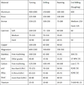
Materials
CNC machines can mill: medium density fiberboard (or MDF), plastics (Delrin/Acetal Copolymer), machine-able wax, polyurethane boards, foam, and even metals (aluminum, brass, bronze, etc). When performing the first pass (roughing cut) should have a feed rate of about 0.005-0.020 IPR (inches per revolution), and the second pass (finishing cut) should have a feed rate of about 0.002-0.004 IPR. Each material has its own recommended speed rate and feed rate. The following table shows suggested values for various materials. (Unit here are in feet per minute), and it was found in this site.
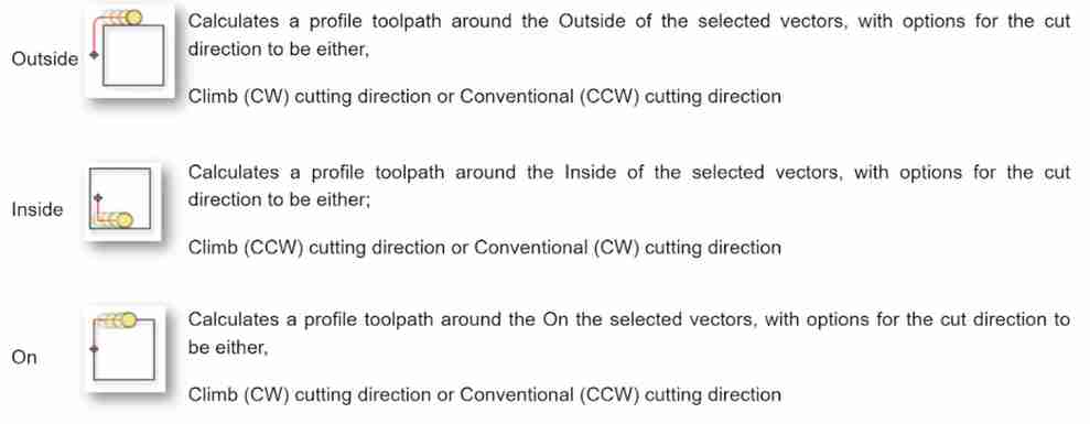
Toolpaths
Toolpaths are the paths the tool is instructed to take to create a given shape. In this case, we will explore the difference between outside, inside and on cuts.
To qualify different types of toolpaths, our team has devised a test.
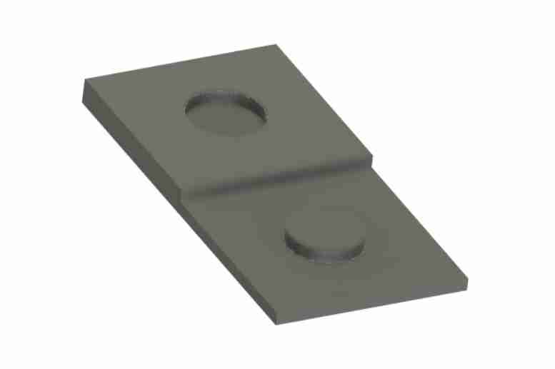
This test will allow us to quantify the difference in different toolpath options (inside, on, outside). This piece is drawn from 4” x 8” piece of stock, so if we run the test 3 times with 3 different toolpath options, we will use a 12” x 8” piece of stock.
We suspect that the different settings will yield different results as they pertain to pockets and bosses. This is why the test includes both a pocket feature and a boss feature. See below for more details.
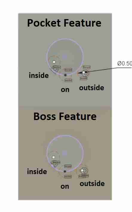
To show why toolpaths are important (whether placed outside or inside an object), our group ran this test.
|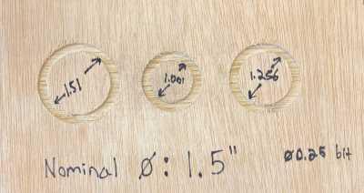 |Three identical circles (measuring 1.5”) were placed in an Aspire file. In the circle on the left, the tool path was placed on the outside portion of the circle. In the circle in the middle the tool path was placed on the inside of the circle. In the circle on the right, the tool path was placed directly on the circle.|
Our group measured the diameter of the circles after each cut. For products to match their actual designed dimensions, it is best to cut out the object using a tool path on the outside of its design. When drilling out holes or pockets, it is best to place the tool path inside of its design. Placing tool paths exactly on the design lines does not provide accurate measurements in the final product (no matter what type of cut is being done).
Team Photos
Shameless chance to post some photos of our team in action.
Unfortunately missing our steady cameraman, but we will be sure to capture him in future weeks!