7a. Electronics design (Students)
The Oscilloscope
Calibrating
The oscilloscope was tested by Jack, Aaron and Alaric. At first they had to familiarize themselves with the tool. Aaron found this youtube video. After watching the video Aaron began reaserching how to calibrate it and came across this youtube video. They began calibrating using the steps are listed below
- Disconnect all inputs
- Utility button
- Do self cal
- Single button
Coding and Testing
After they calibrated the oscilloscope. Alaric and Jack had to upload some code into Jack’s blinky board to test the connection. Alaric wrote the code and they used Jack’s board with Jack also interpreting the results on the oscilloscope. The code is displayed below:
const int ledPin = 3;
//const int pwmval = 128;
void setup() {
  // put your setup code here, to run once:
  pinMode(ledPin, OUTPUT);
}

void loop() {
  // put your main code here, to run repeatedly:
  for (int i = 0; i < 256; i += 5) {
    analogWrite(ledPin, i);
    delay(20);
  }
  for (int i = 256; i >= 0; i -= 5) {
    analogWrite(ledPin, i);
    delay(20);
  }
}
The video shows as the PWM causes the oscilloscope to show the power alternating between high and low, and the lengths of the 2 lines change because the code changes the pwm.
The Multimeter
Multimeter testing was conducted by Andrew and Aarush and Nick and Pari and Jada. The digital multimeter is a tool that can be used to measure a variety of functions, most commonly used to measure Voltage, Current, and Resistance. In this case, Andrew and Aarush and Jada used it to measure the operation of Pari’s hello world PCB.
Diode Checker
A multimeter’s diode checker produces a small voltage between the two test leads that allows us to see the actual forward voltage of the diode when its conducting current.

We used the multimeter to check the operation of the LED on Pari’s board. As you can see, the LED emits light when the multimeter probes are held to it. This shows that the LED is functional and isn’t burnt out.
Voltage
Then Pari,Aarush, Jada, and Andrew all tested the voltage. Voltage is expressed in Volts, so we tried to see how many volts the board has. For an LED to turn on and have power, it needs 5.00v To check we had the proper power and the board did not lack power, we measured the voltage on the power trace,and the multimeter read 5v.


This is exactly what we wanted to see. This assured us that our board has sufficient power and the LED can emit light.
Charge of Batteries (Measuring Amperage, Essentially)
Nick tested the amperage in mA as well as amps of 3 different batteries as well as calculated their power in watts. First, Nick grabbed a couple different 9v batteries from the lab’s 9v drawer and tested each’s voltage and amperage.
To measure voltage, he switched the multimeter to the V (not mV) symbol and hooked the terminals up accordingly to how they lit up on the meter and hit the function key to switch it from AC to DC current voltage.
To measure amperage, he switched the multimeter to the A (not mA) symbol and had to switch the terminals again accordingly aswell as switching from AC to DC once more.
Power was calculated via the equation Amperage (A) * Voltage (V) = Power (Watts)
The batteries below are listed in corelation to the batteries in the photo below with the far left battery being 1 and the far right being 3.
| Battery # | Amperage | Voltage | Power |
|---|---|---|---|
| 1 | 0.078 A | 5.968 v | 0.465 watt |
| 2 | 0.229 A | 7.64 v | 1.749 watt |
| 3 | 0.007 mA | 3.976 v | .027 watt |
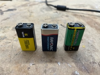
According to a quick google search, Nick found that the amperage should be around 0.4 to 1.2 amps and voltage wise obviously around 9v, meaning all of the above batteries were super undercharged and some pracitcally un-usable.
It also proves that as the charge in the battery decreases, so does the voltage in that battery and of course directly the power as well and that overtime the voltage and current do in fact decrease and are not steady at 9v and 1.2 amps until they suddenly die.