14b. Inputs (CLS Adults)
This week, our group was asked to probe an input devices’ analog and digital signals.
To do this, we used our labs Analog Discovery Systems Kit which is, among many things, an effective USB oscilloscope.
On Monday, April 25, we tried to see if we could determine how to use the Siglent Technologies SDS1102X LCD Digital Oscilloscope in the Charlotte Latin School Fab Lab.
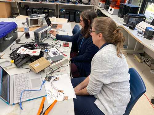
We decided to analyze Barbara Morrow’s PIR breakout board , but unsure of how to connect the PIR sensor to the oscilliscope, we decided to do an Internet search. We found and watched “PIR sensor - testing and looking at sensor output with oscilloscope” and “Infra-red sensor In Oscilloscope PIR Sensor lhi778 opamp Circuit”]. Although we had the manual for the oscilloscope, we never really could tell if we were using it correctly. We were unsure of how to make the adjustments needed to see the waves. The following viedo shows Nidhie and Barbara trying to use Siglent Technologies SDS1102X LCD Digital Oscilloscope.
When the whole group was able to meet on Tuesday, April 26, we used an Analog Discovery 2 (by Digilent) to investigate some of Barbara’s PCB’s (from this week and previous weeks). We recorded this video on Barbara’s iPad, and she used iMovie to merge the two clips together into one video. In working on his final project, classmate, Charlie Horvath, had learned a lot about the Analog Discovery 2 (oscilliscope), and he showed us some of what he knew. Our video is shown below.
Our group also deemed Charlie’s board (used for his input/output week) to be another good circuit to measure for this group assignment, since it involves both an analog input device and a digital toolchain. This board connects an electret microphone dev. board into an AVR 1614 chip. The audio input gets converted into digital using the chips Analog-to-Digital converter (ADC), then back to analog using the chip’s Digital-to-Analog converter (DAC). More detail on the construction of this circuit can be found here.
By probing the Voltage output directly from the analog mic, we can see a smooth analog signal that ranges from 0 to 4.3 V. Since it is a microphone, this signal is centered about the halfway mark of 2.15 V, and stretches up and down towards 0 and 4.3 V. Additionally, we probed the signal coming from the 1614 chip. Specifically, by reading the output from the Digital-to-Analog Converter pin, we can see this same waveform produced after it has been digitally processed by the chip. We can then compare the two waveforms and gain useful insight into the operation of the mic as well as the chips digital toolchain.
The connections were made by connecting the measurement device as follows.
- Analog signal 1+ (orange wire) <-> DAC Output
- Analog signal 2+ (blue wire) <-> mic output
- Ground (black wire) <-> 1614 ground.
Here are the results.
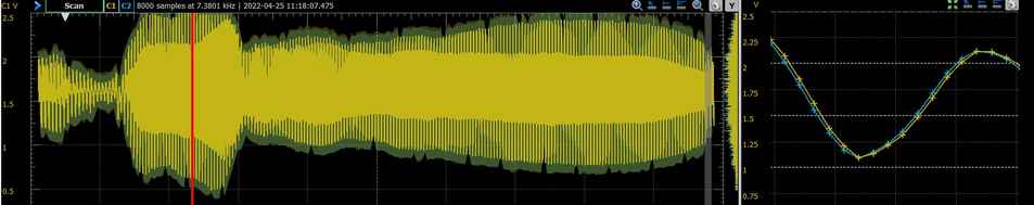
Here we are able to see the smooth analog output from the electret microphone sampled in blue (C2.) Additionally, we are able to see the output of the AVR 1614 chip in yellow (C1), which is simply using the ADC and DAC peripherals to process and reproduce the signal. While, technically the signal it has been converted back to analog at this stage, this is in effect, the closest thing that an electret microphone will offer to a digital output.
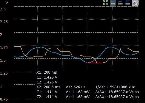
That said, the ADC prescalar is currently set at DIV4. Meaning, the chip’s ADC will sample the incoming wave (blue) at the chip’s clock speed divided by 4.
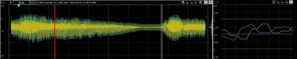
We temporarily changed this value to DIV128 to further explore the digital nature of this output signal. By reducing the sample speed, we noticed two things. First, as expected, the DAC output wave became boxier and less smooth. This is because the DAC is doing its best to interpolate the digital signal back into a smooth analog output. That being said, as we reduce the number of samples available, the data becomes more boxy and we see more artifacts from the digital nature of the signal. Though, perhaps more unexpectedly is the phase lag induced in the DAC output signal. With the prescalar set to DIV4, the phase lag between the two waves was on the order of nanoseconds and completely negligible. In other words, the yellow and blue waves overlapped almost completely. After this change to the prescalar variable, the phase lag was measured 600 microseconds. By slowing down the chip, we effectively took these signals out of phase, and the yellow signal now lags behind the blue. This would be problematic for certain applications.
Overall, the Digital to Analog Discovery kit is proving to be a very effective tool in our arsenal. In addition to being an oscilloscope, it can also serve as a logic analyzer and a waveform generator. In this case, it was the perfect tool to measure the analog output from the mic as well as the signal that was converted to digital and back again.