12. Machine Week (CLS Students Group 1)
Nick, Pari, Andrew, Aarush:
M&M Color Sorter
Slide

Video
Concept
The group originally looked into making some sort of RFID item cabinet, but after this was shot down by the instructors, they went back to the whiteboard and searched for new ideas. Eventually, Pari mentioned the idea of an M&M color sorter. After a bit of discussion, Nick and Aarush drew up some concept images on the whiteboard.
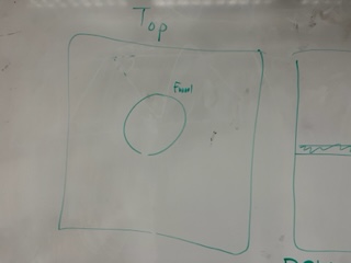
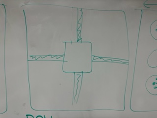
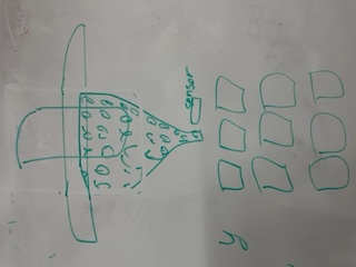
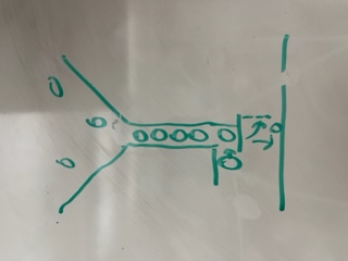
The idea was to have a funnel moving on 2 axes with a color sorter and hatch at the end of said funnel. An M&M would fall to the base of the funnel and would be color checked, then the cnc component would move the funnel over top of the hole designated to that color where the hatch controlled via servo would drop that m and m out into its hole and additionally the number of each sorted color would be tracked on a Raspberry Pi and displayed on a small screen.
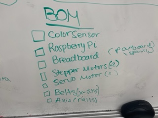
From here, they began creating a bill of materials that would be needed along with the design that had been drawn.
Design Considerations
The M and M sorter would use a few different components: 2 steppers so the funnel could move on both x and y axis as well as a color sensor, all of which would be hooked to the Raspberry Pi. At that time the dropping mechanism was to be a servo motor which would also be connected to the Pi.
CAD and 3D printing
Andrew and Aarush were the ones who worked on CAD designing and 3D printing the various parts for our funnel mechanism, including the funnel itself, wheel mechanism that spins the m&m to get scanned, sensor and motor mounts, and the drop chute to direct the m&m into the hole.
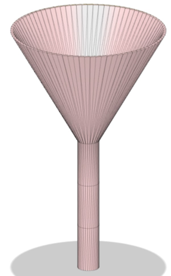
When the plan was laid out, Aarush set to work on designing the funnel that would be used to hold the M&M’s and drop them. From prior design work, Aarush already knew the basis of designing a funnel. In order to send an M&M down the funnel, Aarush made the bottom slot of the funnel big enough to fit an M&M but not too big as to let more than one down at a time.
After he finished the initial design of the funnel, Aarush sent the .stl file to Andrew who worked on creating a slot to insert the servo motor and the hatch that would open and close the bottom of the funnel.
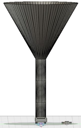
Andrew sent this design back to Aarush who fine tuned the design and printed it on his 3d printer at home. Once the file was sent to prusa slicer, however, it was found that it was too long, so, in order to fix it, Aarush scaled the Z-axis down.
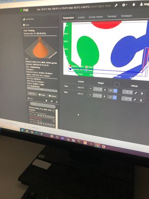
However, due to not having the correct resources for the printer filament, the print failed.
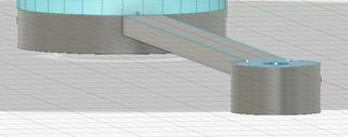
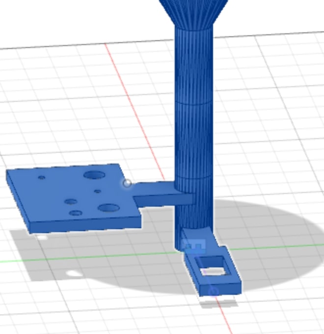
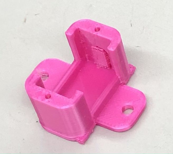
To solve this problem, they waited to print at school but then they were met with another challenge: they forgot the funnel mount. Andrew then worked on designing a mount for the Funnel so that it would attach onto the 2 axis portion of the gantry. He considered the location of the screws that would be needed to mount it onto the actual piece.
Unfortunately, he was not able to print the funnel out because his personal printer had no filament for it, so he waited until he could go back to school and print. In the time when he was waiting, the plan for the gantry changed, in that it was flipped upside down. Also, the group decided not to use a horizontal hatch system and instead use a wheel rotation system of the m&m’s. This was somewhat inspired by this video.
While this didn’t require too many major changes, it did mean that more parts would be added. Although before it was just a hatch and a funnel, now it required a funnel, wheel, and a chute, as well as some mounts for the color sensor and a servo. Andrew then redesigned these parts in Fusion 360 and made everything ready to print.
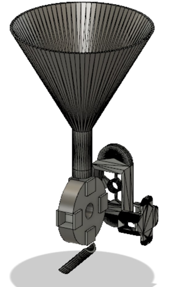
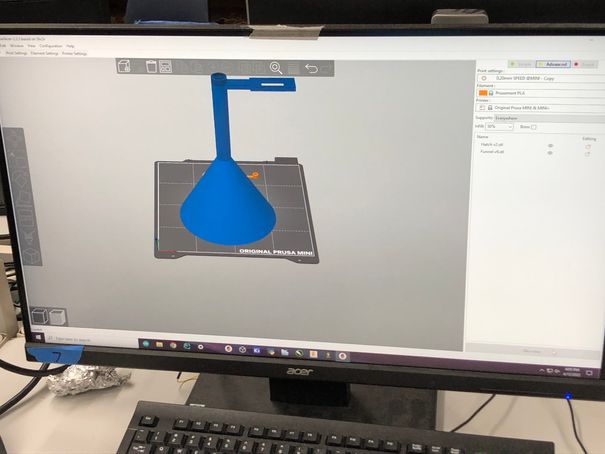
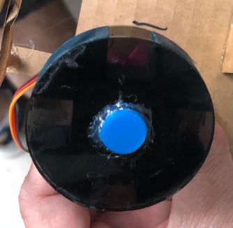
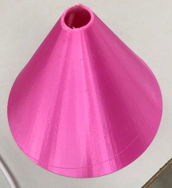
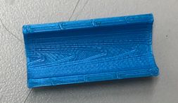
This was the funnel, and as you can see, it’s much shorter than the first iteration design. This is because the object was actually too high to print on the Prusa Printers and it would collide with the top of the machine when printing.

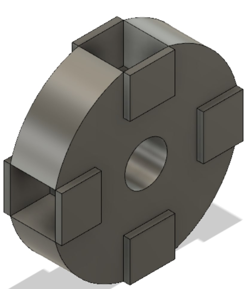
As you can see, this was the wheel design. Andrew, when designing, made sure that it could accommodate an M&M by searching up the diameter and thickness of one. He didn’t have a physical m&m with him so he just found the dimensions online of [1.04 cm diameter] (https://www.latimes.com/food/dailydish/la-dd-mms-mega-three-times-chocolate-hits-stores-20140411-story.html) and .25 in thickness
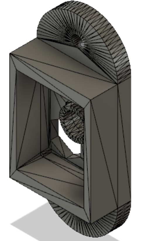
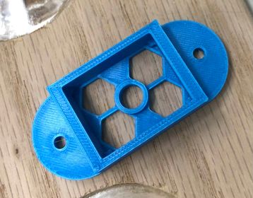
Andrew thought he would look on Thingiverse to try and find a predesigned mount for the TCS3200 Color Sensor, which he found luckily. Here is the credit: KidSwidden’s color sensor
On Thingiverse, he also found a good mount for the micro servo that would turn the wheel. Here is the credit: snblitz’s
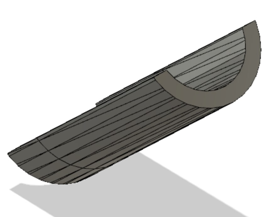
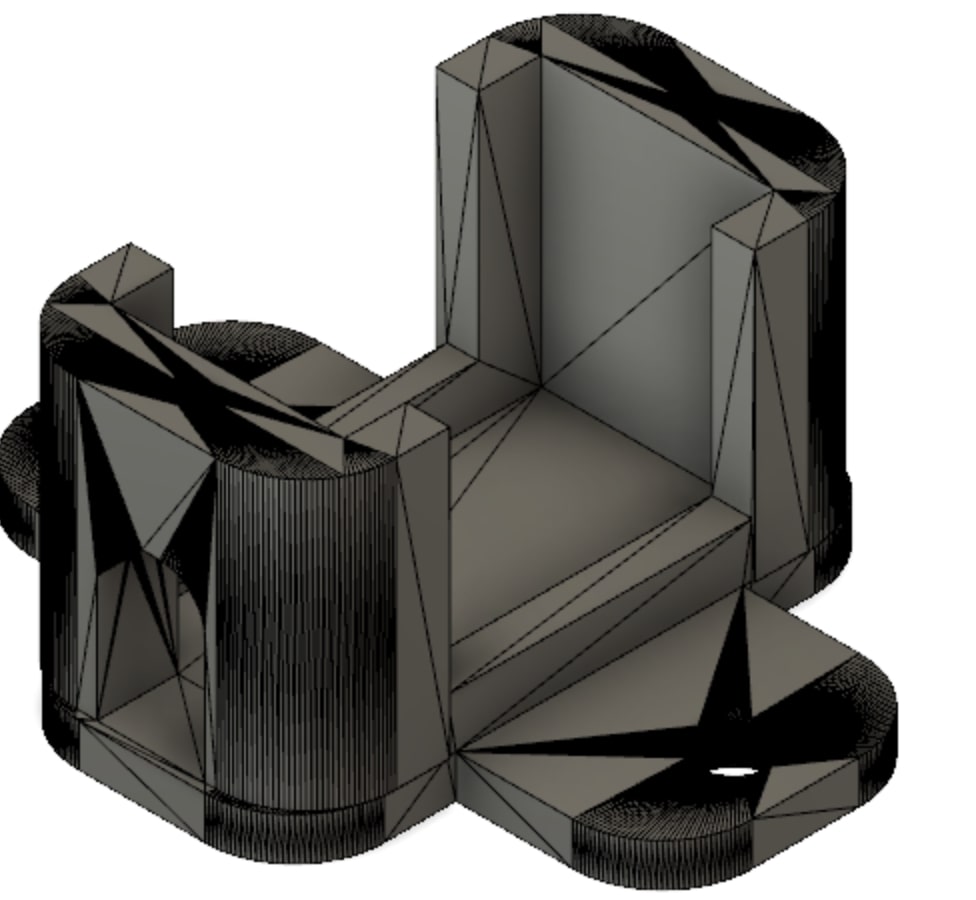
For the chute, Andrew simply took the funnel, and cut the rod piece in half to reveal a slide piece for the m&m.
Now onto 3D printing. For the printing, we didn’t have any major issues since we were using the lab’s Prusa printers instead of our personal Ender 3’s. Our group was planning to print the parts over the long weekend break, but none of our Ender 3’s could be used. Nick’s and Andrew’s printers both happened to be out of filament, and Pari’s and Aarush’s printers were broken.
Funnel Complications
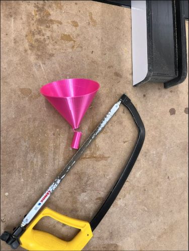
After printed the funnel at school, Aarush checked to see if the M&M’s would fit through. To the entire groups dismay, they did not.
In order to solve this problem, Aarush decided to try sanding down the inside of the funnel tube enough to allow the M&M’s to pass through. After spending some time on this, it was evident this wouldn’t work out, so following the group consensus, he went and sawed off the tube.
Machine Parts
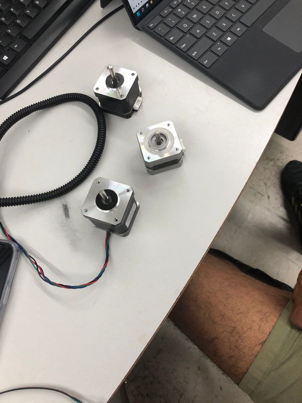
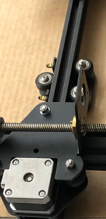
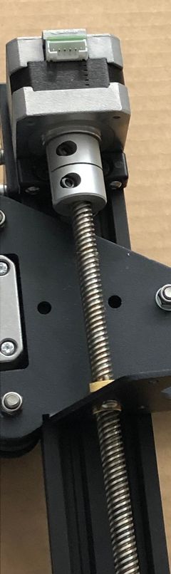
Then, the group looked to get parts such as steppers, belts, metal bars and pipes etc. in order to begin constructing the CNC portion of the machine. Aarush as well as Nick were able to find an old 3D printer and take it apart together to get all the parts the group would need.
From here they had both x and y axes as well as both steppers which would be needed to move on those axes.
Programming
Color Sensor
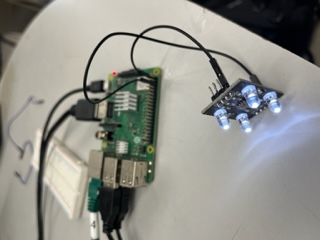
After the design drawings, Nick booted up his Pi from home in order to begin work on the ui program for the sorter which would host statistics for the sorted m and ms as well as some debugging tools. Nick began researching into tutorials on the use of the color sensor which they had luckily found their lab already had in stock. Following a tutorial found here he was able to wire the sensor and using their example code he was able to get readings from that sensor but he saved organizing and polishing the code/converting the readings for later.
GUI Program Development
Nick did coding work for the group’s machine. Since he wanted to incorporate a UI into the final machine to visualize the data collected and to help debug the machine he began working on that. Using an old small Tkinter python script he had from years ago on his pi he began building out the program. He also looked into Tkinter’s documentation found here for additional help passed what was already in the script. Eventually after many hours and lots of trial and error with spacing and positioning, the UI looked like this:
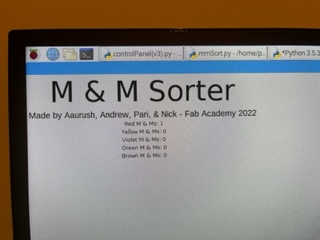
This program featured a sorting button, text objects to list how many of each color were found, a separate console window (which could be toggled using a boolean) as well as some titling and author names at the top.
Stepper Motors
*** Pari add info on site used and research done for that***
Pari and Andrew began working on the steppers initially where she was able to successfully program and get the motors to move using an l298n motor driver and Arduino. This was mainly just a proof of concept to show we could control stepper motors using the l298n motor driver since none of us had done stepper motors for output week
 PARI MORE IMAGES OF STEPPERS
VIDEO OF PARI MOTORS WORKING
By using a very helpful link Pari followed the step while understanding what concepts it was teaching her. She learned about stepper motors and how they work as she has never used them before. Once following all the steps, she and Andrew got the stepper motor to function, which set up a base ground for Aarush and Nick to start the stepper motor and code it using thr Raspberry Pi.
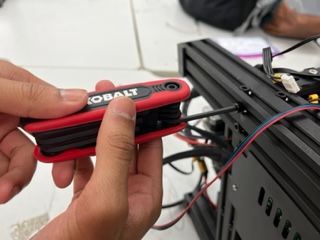
But in the end we would eventually need it to function on the Pi so Aarush began working on the steppers with python. He used the tutorial here. Eventually after wiring and coding, he couldn’t get it to work and had to leave for the night. With that, Nick went to review his code and wiring and found that some of the jumpers were wired incorrectly. He rewired the stepper with success and the code began working and the stepper moving based off input in the python program.
However, Andrew discovered that while the stepper motors indeed turned, they turned at an unusually slow rate. After rewatching the tutorial, he couldn’t figure out why, so he called Dr. Harris over to help him. With Dr. Harris’s help, he discovered the issue, which was that the delay between each motor tick was too high. After making the delay a lower value, he was able to get the stepper motor spinning normally.
During this process, he discovered that the belt axis was much faster than the rod axis, which made sense because the threaded screw provided more resistance than the horizontal belt. Then, Nick and Pari fine-tuned the delay values and explaining a lot about how the stepper worked, information which would later help Nick as the delay values between the belt stepper and the leadscrew stepper needed to be different.
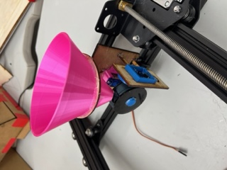
A few days later Nick began working on making the code more streamlined and ready to be implemented into the UI program. He had brought home the machine after the night in which him and Pari had constructed it. He used the same program to successfully move the head of the CNC up and down on the Y axis of the machine.
He then put that code into a function called Move() which could be called from that script and in which the parameter “distance” could be passed to tell it how far to move. The base code was from the tutorial Aarush had used that was linked above, however.
With that, he imported the stepperRod.py file into the GUI program and began implementing it into that.
Combination of UI and Stepper
Nick using both his UI script along with his Stepper script began combining the two in a way that the stepper python file was imported as an object which could be accessed in the UI program’s code. He first added two buttons, a y+ and y- button to test that the leadscrew stepper worked in the UI program. This came with success:
From here, he created a new python file that was a copy of stepperRod.py and named it stepperBelt.py which would manage the belt’s stepper. He changed the delay to the correct delay for the belt stepper and began wiring it to the Pi and changing the values of which the Pi had for the GPIO pins. He got the X axis to be operational and below is a video all about the updates to the UI and to the code:
Lastly he using the displayed coordinate system that he added found the position that each color would drop to and coded the machine to move to those coordinates from it’s current coordinates when a color is detected.
Wooden Bed
Andrew and Pari were the ones who mainly worked on the wooden bed where the m&m’s would fall onto.
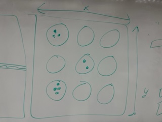
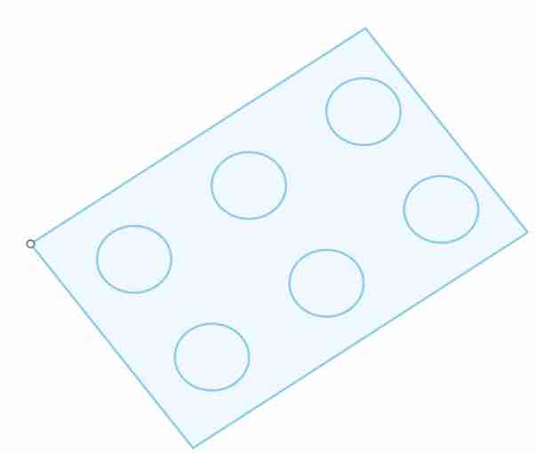
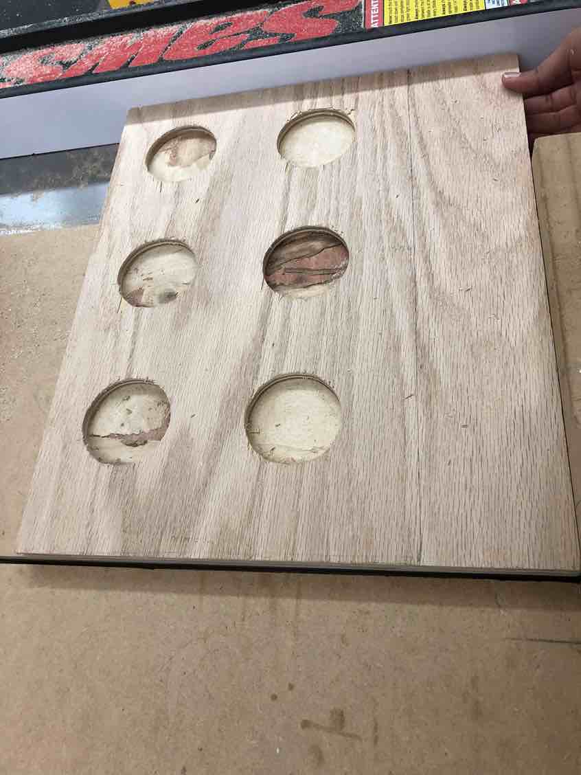
Pari began with designing the file with 6 holes to represent the six colors of m&m’s that the machine sorts: red, orange, yellow, green, blue, brown. She did this using the rectangular pattern tool and doing a 2x3 pattern with the circles in Fusion 360.
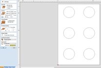
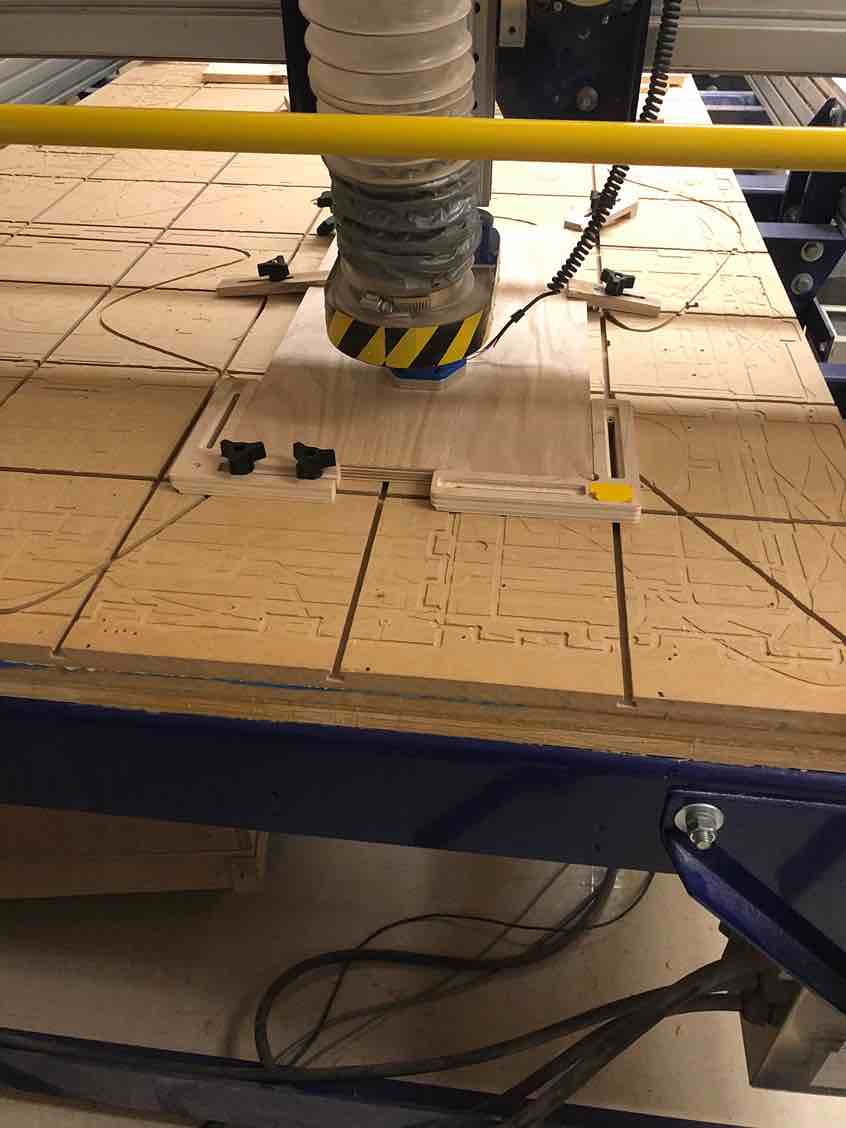
Then, Andrew brought the Fusion file into aspire, where he configured the job settings, material offset, and zeroing. The first time he tried to do a pocket toolpath, he zeroed it off of the machine bed, resulting in problems when it was time to CNC.
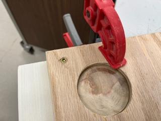
Next it was time to CNC cut. Andrew worked with Pari to clamp the material down using the clamps, something they weren’t very experienced with using. The first time he tried to pocket cut the bed on the shopbot the material came out of the clamps
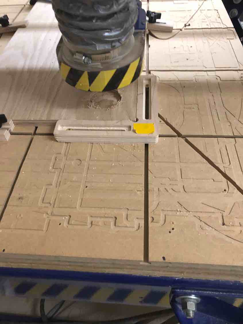
The problem was indeed that Andrew had zeroed the cut off the machine bed instead of the machine cut. Since profile cuts used the machine bed, he had assumed that it was the same for pocket cuts, and was initially confused as to why it was supposed to be zeroed off the machine surface. He did some research and eventually stumbled upon this site that explained the difference perfectly.
“Contrary to machine bed touch off, material surface touch off allows the machine to know what it is cutting. Material surface touch off is used when you need to remove a specific amount of material. If you were to use material surface touch off, the inverse occurs. The machine’s reference point gets flipped to where the 0 point is the top of the material. Now, the machine knows what it is cutting. With that reference, the machine knows that it has to travel downward .25″, therefore resulting in a .25″ pocket depth.”
This explains why pocket cuts need to be zeroed off the machine surface and not the bed, contrary to profile cuts.
With this newfound knowledge, Andrew tweaked the aspire file to have it zero off the machine surface, and worked with Pari to recut. They found success
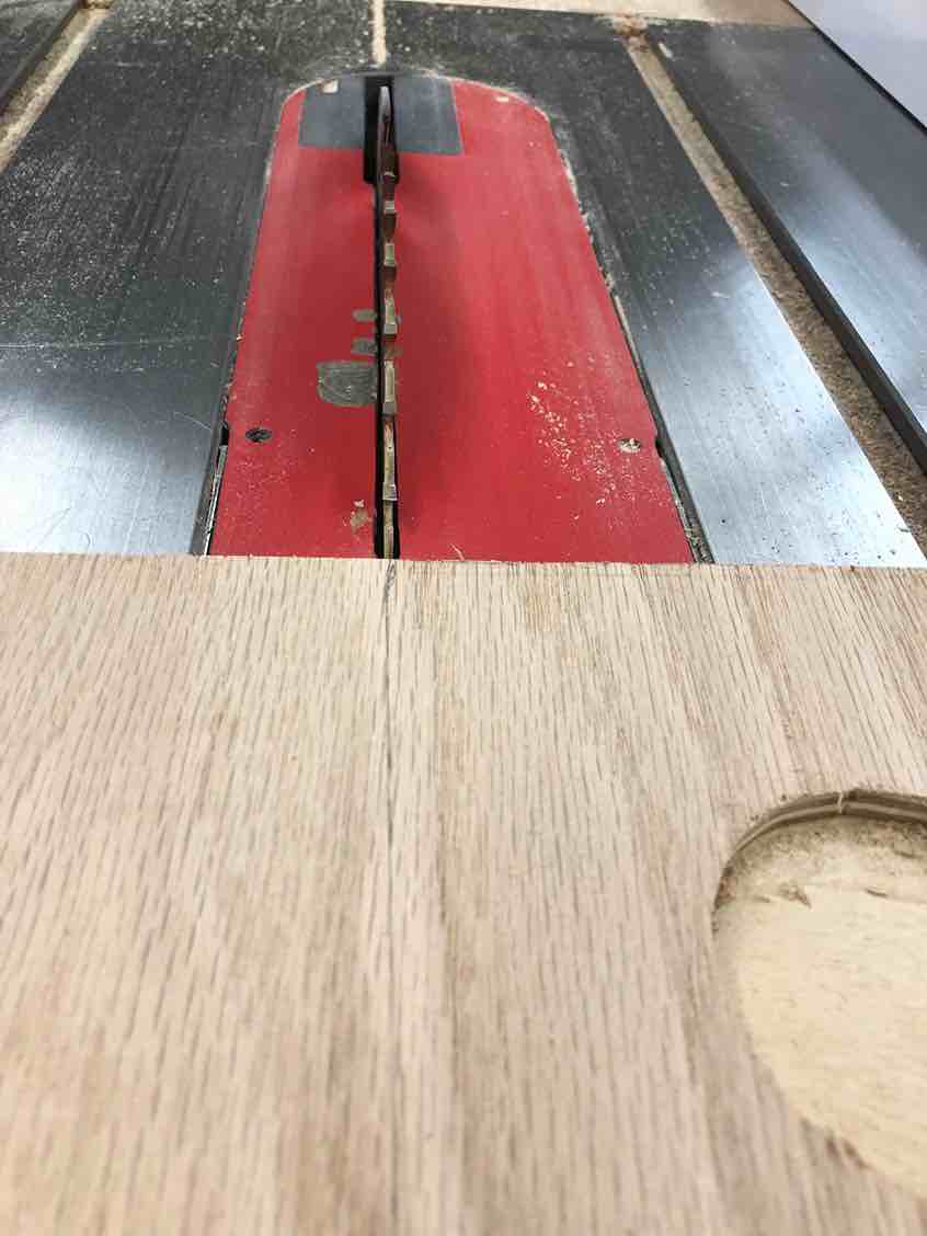
Then, the next issue was that the wood we cut on was too big to fit with our gantry, and we needed to see some of the parts off. Before using the table saw, Mr Dubick gave Pari and Andrew a brief lecture on two different ways to use the table saw, and then had the two practice sawing
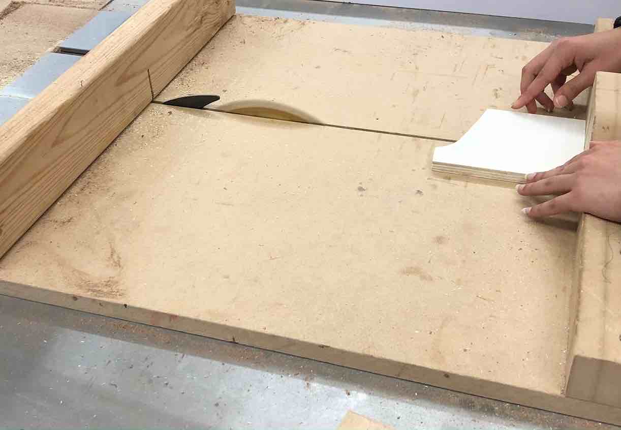
After practicing, it was time for the real deal. Andrew and Pari marked where they were going to saw.
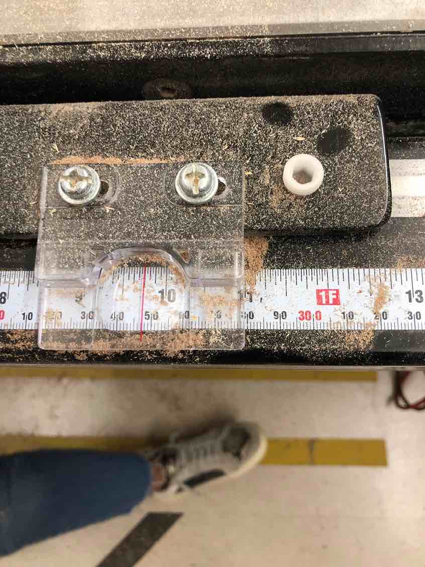
They then used both of the methods to saw off the excess wood.
Next it was time for post processing, where Pari and Andrew used a combination of sandpaper and a sanding router to smoothen out the wood.
The final step that Pari performed on the bed was laser cutting 6 acrylic circles to fit into the holes, for minor sanitation and aesthetic purposes. To cut the acrylic circles to fit perfectly into the M & M tray, Pari designed the file by first mesureing the diameter of the holes using calipers. Once reading that mesurement, she designed 6 circles which were the same.
SCREENSHOT OF COREL DRAW FILE - PARI
While cutting these circles, Pari learned a very important peice of infomation. She could stick masking tape onto the acrlyic to stop it from having burn marks and looking messy. Since M&M were going to thouch he surface of these holes, Pari tried her best to have food safe items. She places blue masking tape on the section where she would cut the 6 acrylic circles and cuts them using the proper laser cutting work flow which she has documented on her personal site and her Fab Academy documentation. Once the cirlces were cut, she decided to rip the tape of them, and Sucess!! There were no burn marks on the acrlyic and the peice of acrlyic fit perfectly into the M&M tray.
Although before this sucess some things Pari sruggled with was the cutting depth of the acrltiyc. She found herself using 1/8 in acyrlic, although when she chose that setting on the Laser Cutter it would no cut through the acrltic. She made the miskae of movinf the peice of acyouc intead of running thr cut once more. To fix this PAri changed the settings which she chose on the laser cutter o 1/4 in acrlyic and it seemed to work fine. It cut perfectly through. So… maybe it was a miscalucation on her part, or something funky was going on with the laser cutter.
*** Pari document here about how you laser cut the circles + PICS and VIDS” ***
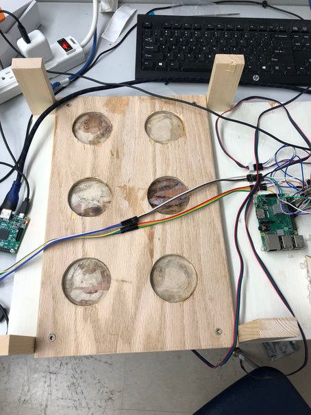
Here was the final bed.
Assembly
Main Machine Frame
Pari and Nick were the ones who cut, constructed, and put together the CNCed would base into what would eventually become the final machine. It also included a screen holder for the eventual small touchscreen that would be installed. First, before the two were allowed to cut or screw anything together, they needed to provide their lab instructor a 3D model of the final build. Nick spent around 30 or so minutes that night making the entire model which turned out like this:
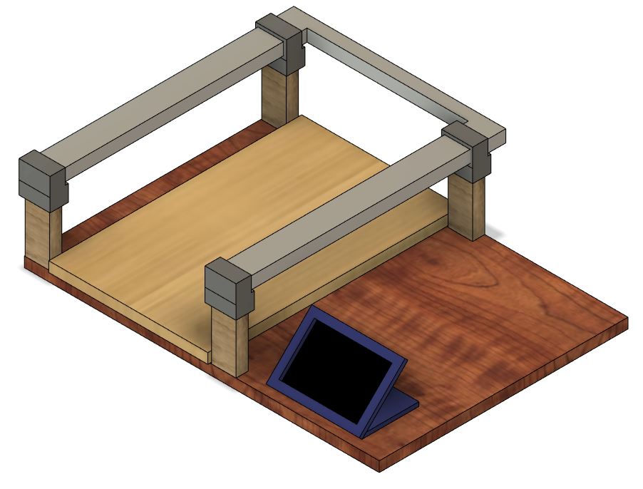
It featured the wooden base with the holes that had been previously CNCed as the top plate on a larger wooden plate along with small wooden beams and the actual cnc axis mounted with 3d printed holders on top of all of that. After proving this design and collecting the needed materials, seen here:

The two went to use the saw to cut them to the correct proportions which they had already marked out when Nick designed the model. They sawed the beams to the correct size then grabbed wood screws to screw it all together, then they screwed the base board in:
Then the beams:
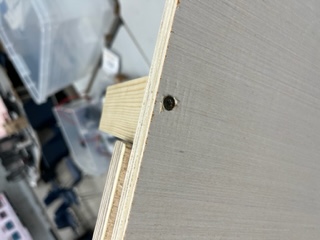
While screwing in one of the beams Pari and Nick ran into a probelm where they drilled the screm a little too close to the edge of the board, hence forcing the wood to pop out. Although to hide this they covered it up with the rest of the wooden beam and turned the model so that beam would be at the back of the machine.
And lastly they laid the CNC part atop the beams for a perfect fit.
Touchscreen & Cleanups
Next Nick hooked up their touchscreen with success.
And he also designed and lasercut a frame.

And then he reorganized the wiring.
Catastrophic Failure
This week, our project ultimately hasn’t worked yet. Unfortunately, our SD card melted right as we were about to put everything together. Our files were not backed up also, so we lost all the code. Nicholas is in the process of rewriting the code, and we will get it working soon.
Major Comeback
After the SD situation, Nick and Pari snagged a new Micro SD and loaded Rasbian (The Pi’s OS) onto it and put it into the previous Pi with sucsess. Now it was simply down to Nick re-writing the code which he did. After a lot of video rewatching and memory as well as looking at our documented tutorials, Nick was able to fully re-write (to a much simpler standard) the code from before and he had the steppers moving, the color sensor reading, and the touchscreen working once more.
Wheel Servo
Nick then looked into tutorials on using a continuious servo on the Pi which would be needed for the turning wheel. He ended up getting the coninious servo to work properly, he now worked on putting together the various pieces of fixturing for which the head of the machine would move with.
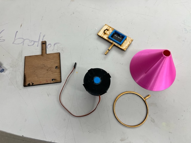
And began combining them:
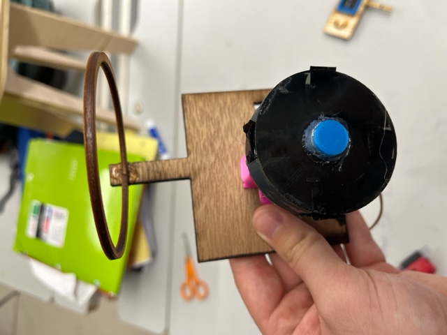
And ended up with this:
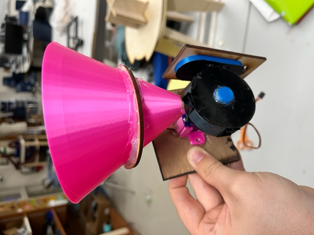
Nick also fascened this to the head of the machine.
Wheel Issue
When testing the new fixturing system, Nick realized that the wheel spun the opposite way of the color sensor. Andrew did some research and found that setting the duty cycle of the servo helped make it spin clockwise.
Color Sensor Calibration
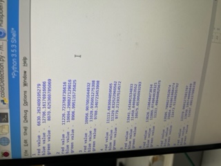
Nick spent tons of time calibraring the color sensor. He logged all of the data in a spreadsheet to find the average values for each color of M and M. He would put an M & M in the wheel, rotate it so it would face the sensor, and then scan and log the color values into a table 5 times for each color. He got this table:
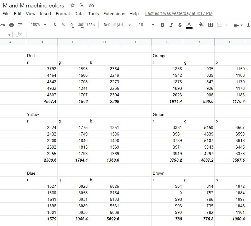
With this table, he coded a funcion in Python that would create a 3 point vector for each color and compare the distances of those to the newly scanned color (the 3 points of the vector being red, green, and blue). Whichever point the new color is closest to would be returned. He inputed these averaged vectors from the spreadsheet to the python code for each color.
It works!
After all of this work, they tested the machine with different colors of M & Ms with sucsess! In the video below, you can see one color of M and M being placed into the wheel, it being dropped in the correct spot, and then the second M & M being scanned, moving the machine, and then dropped into the correct spot.
VIDEO
Codes & Downloads
Below is a zip file with all the code that can be downloaded. Below that is the code written out as well.
from tkinter import *;

import stepperBelt;
import stepperRod;
import colorsense;
import wheelControl;

cncX = 0;
cncY = 0;

mainWindow = Tk();

mainWindow.title("M & M Sorter");
mainWindow.geometry('800x400');

def moveCNC(x, y):
    global cncX;
    global cncY;
    print("Move");
    stepperBelt.Move(x);
    cncX += x;
    stepperRod.Move(y);
    cncY += y;
    cncLocatText.config(text="CNC Position: (" + str(cncX) + ", " + str(cncY) + ")");

def moveCNCnonRelative(x, y):
    global cncX;
    global cncY;
    print("Move Non-Relative");
    toMoveX = x - cncX;
    toMoveY = y - cncY;
    moveCNC(toMoveX, toMoveY);
    cncX = x;
    cncY = y;
    cncLocatText.config(text="CNC Position: (" + str(cncX) + ", " + str(cncY) + ")");

def Sort():
    n = 0;
    while (n < 20):
        RotateWheel();
        onColorDetected(colorsense.retrieveColor());
        n = n + 1;

def RotateWheel():
    print("Rotating...");
    wheelControl.Rotate();

def Zero():
    global cncX;
    global cncY;
    print("Zeroing...");
    cncX = 0;
    cncY = 0;
    cncLocatText.config(text="CNC Position: (" + str(cncX) + ", " + str(cncY) + ")");

def xUp():
    print("X Up...");
    moveCNC(100, 0);

def xDown():
    print("X Down...");
    moveCNC(-100, 0);

def yUp():
    print("Y Up...");
    moveCNC(0, 400);

def yDown():
    print("Y Down...");
    moveCNC(0, -400);

def Home():
    moveCNCnonRelative(0, 0);

def onColorDetected(color):
    #PLUGIN COORDS
    print("COLOR: ", color);
    if (color == "Red"):
        moveCNCnonRelative(0, 0);
        print("Found red...");
    elif (color == "Orange"):
        moveCNCnonRelative(-1100, 0);
        print("Found orange...");
    elif (color == "Yellow"):
        moveCNCnonRelative(0, 6000);
        print("Found yellow...");
    elif (color == "Green"):
        moveCNCnonRelative(-1100, 6000);
        print("Found green...");
    elif (color == "Blue"):
        moveCNCnonRelative(0, 10000);
        print("Found blue...");
    elif (color == "Brown"):
        moveCNCnonRelative(-1100, 10000);
        print("Found brown...");
    RotateWheel();

def ReadRGB():
    colorsense.retrieveColor();

def RotateWheel():
    wheelControl.Rotate();

cncLocatText = Label(mainWindow, text="CNC Position: (" + str(cncX) + ", " + str(cncY) + ")");
cncLocatText.place(x=325,y=50);

rgbButton = Button(mainWindow, text="Read RGB", width=10, height=3, bg='blue', fg='white', command=ReadRGB).place(x=350,y=140);
sortButton = Button(mainWindow, text="Sort", width=10, height=3, bg='blue', fg='white', command=Sort).place(x=350,y=200);
zeroButton = Button(mainWindow, text="Zero", width=10, height=3, bg='blue', fg='white', command=Zero).place(x=350,y=260);
homeButton = Button(mainWindow, text="Home", width=10, height=3, bg='blue', fg='white', command=Home).place(x=350,y=320);
wheelButton = Button(mainWindow, text="Rotate Wheel", width=10, height=3, bg='blue', fg='white', command=RotateWheel).place(x=350,y=80);

xUpButton = Button(mainWindow, text="X+", width=10, height=3, bg='blue', fg='white', command=xUp).place(x=200,y=260);
xDownButton = Button(mainWindow, text="X-", width=10, height=3, bg='blue', fg='white', command=xDown).place(x=200,y=320);

yUpButton = Button(mainWindow, text="Y+", width=10, height=3, bg='blue', fg='white', command=yUp).place(x=500,y=260);
yDownButton = Button(mainWindow, text="Y-", width=10, height=3, bg='blue', fg='white', command=yDown).place(x=500,y=320);
import RPi.GPIO as GPIO
import time

out1 = 19
out2 = 21
out3 = 16
out4 = 18

delay = 0.001;

def Initialize():
    GPIO.setmode(GPIO.BOARD)
    GPIO.setup(out1,GPIO.OUT)
    GPIO.setup(out2,GPIO.OUT)
    GPIO.setup(out3,GPIO.OUT)
    GPIO.setup(out4,GPIO.OUT)

def Move(dist):
    i=0
    positive=0
    negative=0
    y=0
    Initialize();
    n=0;
    while(n==0):
        n=1;
        GPIO.output(out1,GPIO.LOW)
        GPIO.output(out2,GPIO.LOW)
        GPIO.output(out3,GPIO.LOW)
        GPIO.output(out4,GPIO.LOW)
        x = int(dist);
        if x>0:
            for y in range(x,0,-1):
                if negative==1:
                    if i==7:
                        i=0
                    else:
                        i=i+1
                    y=y+2
                    negative=0
                positive=1
                #print((x+1)-y)
                if i==0:
                    GPIO.output(out1,GPIO.HIGH)
                    GPIO.output(out2,GPIO.LOW)
                    GPIO.output(out3,GPIO.LOW)
                    GPIO.output(out4,GPIO.LOW)
                    time.sleep(delay)
                    #time.sleep(1)
                elif i==1:
                    GPIO.output(out1,GPIO.HIGH)
                    GPIO.output(out2,GPIO.HIGH)
                    GPIO.output(out3,GPIO.LOW)
                    GPIO.output(out4,GPIO.LOW)
                    time.sleep(delay)
                    #time.sleep(1)
                elif i==2:
                    GPIO.output(out1,GPIO.LOW)
                    GPIO.output(out2,GPIO.HIGH)
                    GPIO.output(out3,GPIO.LOW)
                    GPIO.output(out4,GPIO.LOW)
                    time.sleep(delay)
                    #time.sleep(1)
                elif i==3:
                    GPIO.output(out1,GPIO.LOW)
                    GPIO.output(out2,GPIO.HIGH)
                    GPIO.output(out3,GPIO.HIGH)
                    GPIO.output(out4,GPIO.LOW)
                    time.sleep(delay)
                    #time.sleep(1)
                elif i==4:
                    GPIO.output(out1,GPIO.LOW)
                    GPIO.output(out2,GPIO.LOW)
                    GPIO.output(out3,GPIO.HIGH)
                    GPIO.output(out4,GPIO.LOW)
                    time.sleep(delay)
                    #time.sleep(1)
                elif i==5:
                    GPIO.output(out1,GPIO.LOW)
                    GPIO.output(out2,GPIO.LOW)
                    GPIO.output(out3,GPIO.HIGH)
                    GPIO.output(out4,GPIO.HIGH)
                    time.sleep(delay)
                    #time.sleep(1)
                elif i==6:
                    GPIO.output(out1,GPIO.LOW)
                    GPIO.output(out2,GPIO.LOW)
                    GPIO.output(out3,GPIO.LOW)
                    GPIO.output(out4,GPIO.HIGH)
                    time.sleep(delay)
                    #time.sleep(1)
                elif i==7:
                    GPIO.output(out1,GPIO.HIGH)
                    GPIO.output(out2,GPIO.LOW)
                    GPIO.output(out3,GPIO.LOW)
                    GPIO.output(out4,GPIO.HIGH)
                    time.sleep(delay)
                    #time.sleep(1)
                if i==7:
                    i=0
                    continue
                i=i+1


        elif x<0:
            x=x*-1
            for y in range(x,0,-1):
                if positive==1:
                    if i==0:
                        i=7
                    else:
                        i=i-1
                    y=y+3
                    positive=0
                negative=1
                #print((x+1)-y)
                if i==0:
                    GPIO.output(out1,GPIO.HIGH)
                    GPIO.output(out2,GPIO.LOW)
                    GPIO.output(out3,GPIO.LOW)
                    GPIO.output(out4,GPIO.LOW)
                    time.sleep(delay)
                    #time.sleep(1)
                elif i==1:
                    GPIO.output(out1,GPIO.HIGH)
                    GPIO.output(out2,GPIO.HIGH)
                    GPIO.output(out3,GPIO.LOW)
                    GPIO.output(out4,GPIO.LOW)
                    time.sleep(delay)
                    #time.sleep(1)
                elif i==2:
                    GPIO.output(out1,GPIO.LOW)
                    GPIO.output(out2,GPIO.HIGH)
                    GPIO.output(out3,GPIO.LOW)
                    GPIO.output(out4,GPIO.LOW)
                    time.sleep(delay)
                    #time.sleep(1)
                elif i==3:
                    GPIO.output(out1,GPIO.LOW)
                    GPIO.output(out2,GPIO.HIGH)
                    GPIO.output(out3,GPIO.HIGH)
                    GPIO.output(out4,GPIO.LOW)
                    time.sleep(delay)
                    #time.sleep(1)
                elif i==4:
                    GPIO.output(out1,GPIO.LOW)
                    GPIO.output(out2,GPIO.LOW)
                    GPIO.output(out3,GPIO.HIGH)
                    GPIO.output(out4,GPIO.LOW)
                    time.sleep(delay)
                    #time.sleep(1)
                elif i==5:
                    GPIO.output(out1,GPIO.LOW)
                    GPIO.output(out2,GPIO.LOW)
                    GPIO.output(out3,GPIO.HIGH)
                    GPIO.output(out4,GPIO.HIGH)
                    time.sleep(delay)
                    #time.sleep(1)
                elif i==6:
                    GPIO.output(out1,GPIO.LOW)
                    GPIO.output(out2,GPIO.LOW)
                    GPIO.output(out3,GPIO.LOW)
                    GPIO.output(out4,GPIO.HIGH)
                    time.sleep(delay)
                    #time.sleep(1)
                elif i==7:
                    GPIO.output(out1,GPIO.HIGH)
                    GPIO.output(out2,GPIO.LOW)
                    GPIO.output(out3,GPIO.LOW)
                    GPIO.output(out4,GPIO.HIGH)
                    time.sleep(delay)
                    #time.sleep(1)
                if i==0:
                    i=7
                    continue
                i=i-1
import RPi.GPIO as GPIO
import time

out1 = 13
out2 = 11
out3 = 15
out4 = 12

delay = 0.001;

def Initialize():
    GPIO.setmode(GPIO.BOARD)
    GPIO.setup(out1,GPIO.OUT)
    GPIO.setup(out2,GPIO.OUT)
    GPIO.setup(out3,GPIO.OUT)
    GPIO.setup(out4,GPIO.OUT)

def Move(dist):
    i=0
    positive=0
    negative=0
    y=0
    Initialize();
    n=0;
    while(n==0):
        n=1;
        GPIO.output(out1,GPIO.LOW)
        GPIO.output(out2,GPIO.LOW)
        GPIO.output(out3,GPIO.LOW)
        GPIO.output(out4,GPIO.LOW)
        x = int(dist);
        if x>0:
            for y in range(x,0,-1):
                if negative==1:
                    if i==7:
                        i=0
                    else:
                        i=i+1
                    y=y+2
                    negative=0
                positive=1
                #print((x+1)-y)
                if i==0:
                    GPIO.output(out1,GPIO.HIGH)
                    GPIO.output(out2,GPIO.LOW)
                    GPIO.output(out3,GPIO.LOW)
                    GPIO.output(out4,GPIO.LOW)
                    time.sleep(delay)
                    #time.sleep(1)
                elif i==1:
                    GPIO.output(out1,GPIO.HIGH)
                    GPIO.output(out2,GPIO.HIGH)
                    GPIO.output(out3,GPIO.LOW)
                    GPIO.output(out4,GPIO.LOW)
                    time.sleep(delay)
                    #time.sleep(1)
                elif i==2:
                    GPIO.output(out1,GPIO.LOW)
                    GPIO.output(out2,GPIO.HIGH)
                    GPIO.output(out3,GPIO.LOW)
                    GPIO.output(out4,GPIO.LOW)
                    time.sleep(delay)
                    #time.sleep(1)
                elif i==3:
                    GPIO.output(out1,GPIO.LOW)
                    GPIO.output(out2,GPIO.HIGH)
                    GPIO.output(out3,GPIO.HIGH)
                    GPIO.output(out4,GPIO.LOW)
                    time.sleep(delay)
                    #time.sleep(1)
                elif i==4:
                    GPIO.output(out1,GPIO.LOW)
                    GPIO.output(out2,GPIO.LOW)
                    GPIO.output(out3,GPIO.HIGH)
                    GPIO.output(out4,GPIO.LOW)
                    time.sleep(delay)
                    #time.sleep(1)
                elif i==5:
                    GPIO.output(out1,GPIO.LOW)
                    GPIO.output(out2,GPIO.LOW)
                    GPIO.output(out3,GPIO.HIGH)
                    GPIO.output(out4,GPIO.HIGH)
                    time.sleep(delay)
                    #time.sleep(1)
                elif i==6:
                    GPIO.output(out1,GPIO.LOW)
                    GPIO.output(out2,GPIO.LOW)
                    GPIO.output(out3,GPIO.LOW)
                    GPIO.output(out4,GPIO.HIGH)
                    time.sleep(delay)
                    #time.sleep(1)
                elif i==7:
                    GPIO.output(out1,GPIO.HIGH)
                    GPIO.output(out2,GPIO.LOW)
                    GPIO.output(out3,GPIO.LOW)
                    GPIO.output(out4,GPIO.HIGH)
                    time.sleep(delay)
                    #time.sleep(1)
                if i==7:
                    i=0
                    continue
                i=i+1


        elif x<0:
            x=x*-1
            for y in range(x,0,-1):
                if positive==1:
                    if i==0:
                        i=7
                    else:
                        i=i-1
                    y=y+3
                    positive=0
                negative=1
                #print((x+1)-y)
                if i==0:
                    GPIO.output(out1,GPIO.HIGH)
                    GPIO.output(out2,GPIO.LOW)
                    GPIO.output(out3,GPIO.LOW)
                    GPIO.output(out4,GPIO.LOW)
                    time.sleep(delay)
                    #time.sleep(1)
                elif i==1:
                    GPIO.output(out1,GPIO.HIGH)
                    GPIO.output(out2,GPIO.HIGH)
                    GPIO.output(out3,GPIO.LOW)
                    GPIO.output(out4,GPIO.LOW)
                    time.sleep(delay)
                    #time.sleep(1)
                elif i==2:
                    GPIO.output(out1,GPIO.LOW)
                    GPIO.output(out2,GPIO.HIGH)
                    GPIO.output(out3,GPIO.LOW)
                    GPIO.output(out4,GPIO.LOW)
                    time.sleep(delay)
                    #time.sleep(1)
                elif i==3:
                    GPIO.output(out1,GPIO.LOW)
                    GPIO.output(out2,GPIO.HIGH)
                    GPIO.output(out3,GPIO.HIGH)
                    GPIO.output(out4,GPIO.LOW)
                    time.sleep(delay)
                    #time.sleep(1)
                elif i==4:
                    GPIO.output(out1,GPIO.LOW)
                    GPIO.output(out2,GPIO.LOW)
                    GPIO.output(out3,GPIO.HIGH)
                    GPIO.output(out4,GPIO.LOW)
                    time.sleep(delay)
                    #time.sleep(1)
                elif i==5:
                    GPIO.output(out1,GPIO.LOW)
                    GPIO.output(out2,GPIO.LOW)
                    GPIO.output(out3,GPIO.HIGH)
                    GPIO.output(out4,GPIO.HIGH)
                    time.sleep(delay)
                    #time.sleep(1)
                elif i==6:
                    GPIO.output(out1,GPIO.LOW)
                    GPIO.output(out2,GPIO.LOW)
                    GPIO.output(out3,GPIO.LOW)
                    GPIO.output(out4,GPIO.HIGH)
                    time.sleep(delay)
                    #time.sleep(1)
                elif i==7:
                    GPIO.output(out1,GPIO.HIGH)
                    GPIO.output(out2,GPIO.LOW)
                    GPIO.output(out3,GPIO.LOW)
                    GPIO.output(out4,GPIO.HIGH)
                    time.sleep(delay)
                    #time.sleep(1)
                if i==0:
                    i=7
                    continue
                i=i-1
    GPIO.output(out1,GPIO.LOW)
    GPIO.output(out2,GPIO.LOW)
    GPIO.output(out3,GPIO.LOW)
    GPIO.output(out4,GPIO.LOW)

#Move(400);
import RPi.GPIO as GPIO;
import time;
def Rotate():
    GPIO.setmode(GPIO.BOARD);
    GPIO.setup(32, GPIO.OUT);
    p = GPIO.PWM(32, 50);
    p.start(20);
    p.ChangeDutyCycle(5);
    time.sleep(0.12);
    p.stop();
    GPIO.cleanup();
import RPi.GPIO as GPIO
import time
import numpy as np

s2 = 22
s3 = 24
signal = 26
NUM_CYCLES = 10

red = np.array([4567, 1568, 2309]);
orange = np.array([1914, 890, 1176]);
yellow = np.array([2300, 1794, 1360]);
green = np.array([3798, 4887, 3507]);
blue = np.array([1579, 3045, 5692]);
brown = np.array([992, 776, 1080]);

def discoverColor(r, g, b):
    finalColor = "Null";

    newColor = np.array([r, g, b]);
    distances = [];

    redDistSqrd = np.sum((newColor-red)**2, axis=0);
    redDist = np.sqrt(redDistSqrd);

    distances.append(redDist);

    ##########

    orangeDistSqrd = np.sum((newColor-orange)**2, axis=0);
    orangeDist = np.sqrt(orangeDistSqrd);

    distances.append(orangeDist);

    ##########

    yellowDistSqrd = np.sum((newColor-yellow)**2, axis=0);
    yellowDist = np.sqrt(yellowDistSqrd);

    distances.append(yellowDist);

    ##########

    greenDistSqrd = np.sum((newColor-green)**2, axis=0);
    greenDist = np.sqrt(greenDistSqrd);

    distances.append(greenDist);

    ##########

    blueDistSqrd = np.sum((newColor-blue)**2, axis=0);
    blueDist = np.sqrt(blueDistSqrd);

    distances.append(blueDist);

    ##########

    brownDistSqrd = np.sum((newColor-brown)**2, axis=0);
    brownDist = np.sqrt(brownDistSqrd);

    distances.append(brownDist);

    distNumber = 9999;
    i = 0;
    closestColorDist = 0;

    for dist in distances:
        print(str(i));
        if (dist < distNumber):
            closestColorDist = i;
            distNumber = dist;
        i = i + 1;
    i = closestColorDist;

    if (i==0):
        finalColor = "Red";
    elif (i==1):
        finalColor = "Orange";
    elif (i==2):
        finalColor = "Yellow";
    elif (i==3):
        finalColor = "Green";
    elif (i==4):
        finalColor = "Blue";
    elif (i==5):
        finalColor = "Brown";
    print(finalColor);
    return finalColor;

def setup():
  GPIO.setmode(GPIO.BOARD)
  GPIO.setup(signal,GPIO.IN, pull_up_down=GPIO.PUD_UP)
  GPIO.setup(s2,GPIO.OUT)
  GPIO.setup(s3,GPIO.OUT)
  print("\n")

def printRGBRaw():
      setup();
      temp = 1
      n = 0;
      while(n==0):
        n=1;
        #print("Hello");
        GPIO.output(s2,GPIO.LOW)
        GPIO.output(s3,GPIO.LOW)
        time.sleep(0.3)
        start = time.time()
        #print("Hello");
        for impulse_count in range(NUM_CYCLES):
          GPIO.wait_for_edge(signal, GPIO.FALLING)
        duration = time.time() - start      #seconds to run for loop
        red  = NUM_CYCLES / duration   #in Hz
        #print("red value - ",red)
        #print("Hello");

        GPIO.output(s2,GPIO.LOW)
        GPIO.output(s3,GPIO.HIGH)
        time.sleep(0.3)
        start = time.time()
        for impulse_count in range(NUM_CYCLES):
          GPIO.wait_for_edge(signal, GPIO.FALLING)
        duration = time.time() - start
        blue = NUM_CYCLES / duration
        #print("blue value - ",blue)

        GPIO.output(s2,GPIO.HIGH)
        GPIO.output(s3,GPIO.HIGH)
        time.sleep(0.3)
        start = time.time()
        for impulse_count in range(NUM_CYCLES):
          GPIO.wait_for_edge(signal, GPIO.FALLING)
        duration = time.time() - start
        green = NUM_CYCLES / duration
        #print("green value - ",green)
        time.sleep(2)
      print("(" + str(red) + ", " + str(green) + ", " + str(blue) + ")");

def retrieveColor():
      setup();
      temp = 1
      n = 0;
      while(n==0):
        n=1;
        GPIO.output(s2,GPIO.LOW)
        GPIO.output(s3,GPIO.LOW)
        time.sleep(0.3)
        #print("Hello");
        start = time.time()
        #print("Hello");
        for impulse_count in range(NUM_CYCLES):
          GPIO.wait_for_edge(signal, GPIO.FALLING)
        duration = time.time() - start      #seconds to run for loop
        red  = NUM_CYCLES / duration   #in Hz
        #print("red value - ",red)
        #print("Hello");

        GPIO.output(s2,GPIO.LOW)
        GPIO.output(s3,GPIO.HIGH)
        time.sleep(0.3)
        start = time.time()
        for impulse_count in range(NUM_CYCLES):
          GPIO.wait_for_edge(signal, GPIO.FALLING)
        duration = time.time() - start
        blue = NUM_CYCLES / duration
        #print("blue value - ",blue)

        GPIO.output(s2,GPIO.HIGH)
        GPIO.output(s3,GPIO.HIGH)
        time.sleep(0.3)
        start = time.time()
        for impulse_count in range(NUM_CYCLES):
          GPIO.wait_for_edge(signal, GPIO.FALLING)
        duration = time.time() - start
        green = NUM_CYCLES / duration
        #print("green value - ",green)
        time.sleep(2)
      return discoverColor(red, green, blue);