6a. 3D Production (Students)
Benchy Jack and Aaron
Ender 3
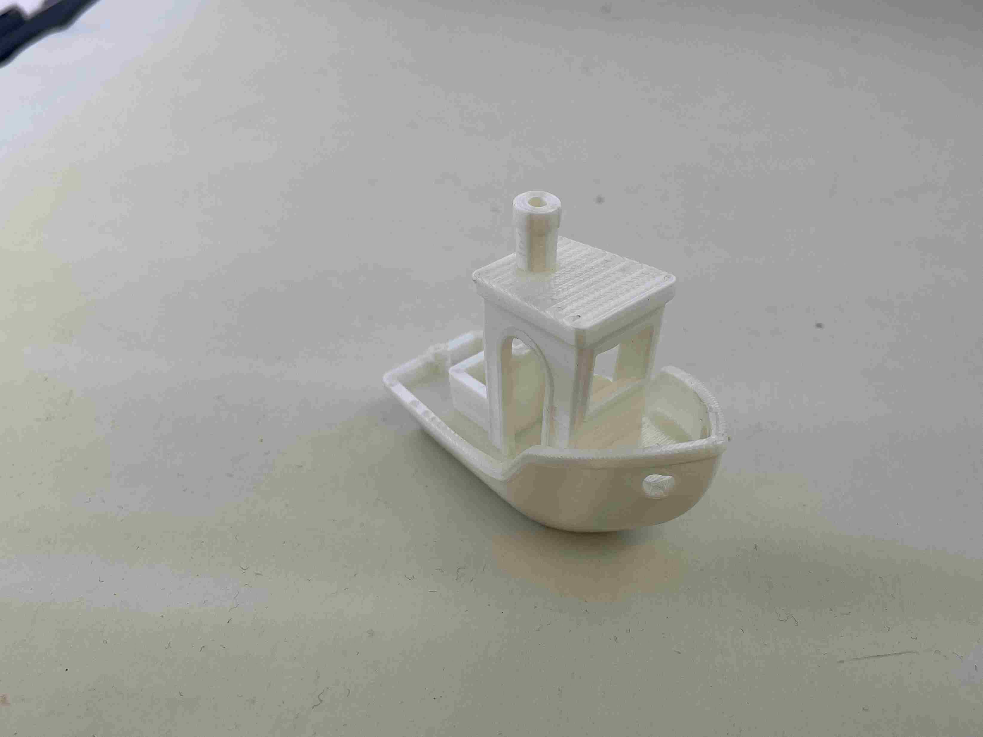
Aaron used a generic PLA with a bed temperature of 60 C and nozzle temperature 195 C. Looking at the benchy from the Ender 3 Pro, the first thing to notice is the top circle. The circle isn’t perfectly round and has more characteristics of an ellipsis. This means the y or x-axis belt needs to be tightened. The hull of the benchy looked clean and when compared to the benchy coming from the Prusa Mini there wasn’t a major difference. The hull was smooth with no zits or abnormalities, also the hull wasn’t hanging, so the extruder and bed temperature were at a good level. There was very little stringing in between the pillars of the board so the retraction distance along with the extrusion were configured correctly. Finally the letters at the bottom were readable, there is room for improvement (i.e. adjusting the first layer height). There was some variation between size on the hu but the benchy overall turned out very nicely for a relatively inexpensive 3D printer.
Prusa Mini’s
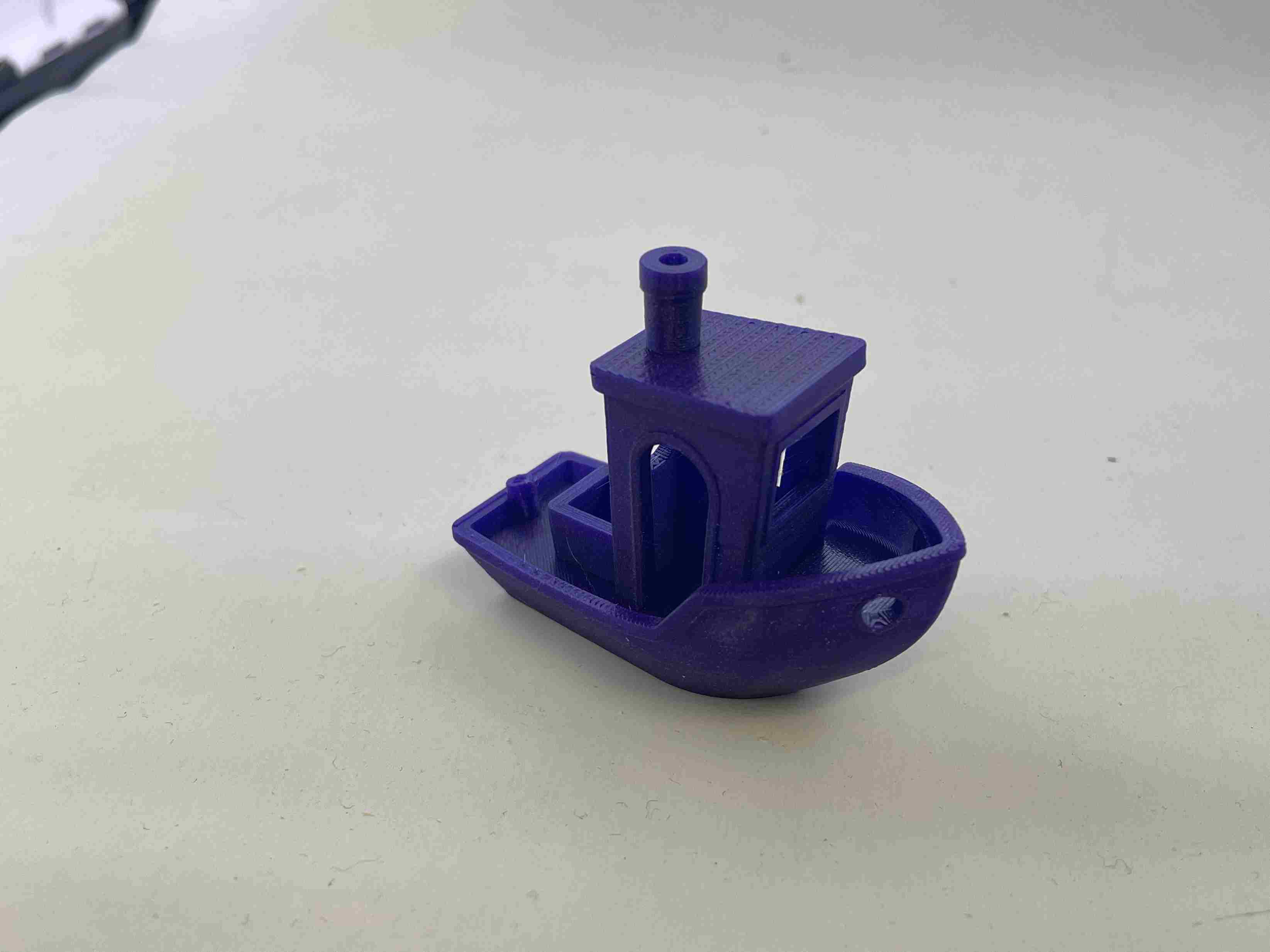
For the Prusa Mini Aaron used PLA with a bed temperature of 60 C and nozzle temperature of 205 C. The benchy from the Prusa Mini looked a little bit better than the Ender 3 one. For example, the circle on the top of the board was much better, Aaron used a caliper to measure the distance and they were equal. This means both the x and y-axis are tightened correctly. The hull looked great too. It was smooth with no zits. The hull also didn’t experience hanging so the extruder and the retraction rate were configured well. Stringing became a small issue in the beginning of the printing process. Around the inside of the hull and around the pillars there was some stringing, not a lot but noticeable. The first layer of the printer was calibrated nicely as shown with the bottom layer of the boat. The letters were extremely clear, with even the smaller letters having just as much detail as the large ones.
Resin Printers:
Durable Resin:
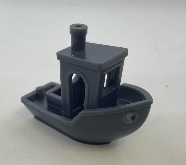
Jack used durable Resin to print a benchy. When analyzing the benchy from this printer it was immediately apparent that it was more detailed and was composed of more layers than the benchys that were 3d printed. The top circle was perfect and was not lopsided one way or another. This proves that the x and y axis were perfectly calibrated. The hull of the benchy was smooth until it got to the bottom.where there was a collection of climbed resin. This shows that the z axis was lined up perfectly, however some of this particular resin would collect in divots and gaps. There was absolutely no stringing between the pillars of the cabin. This is because the resin printer operates differently than the 3d printer and does everything at once instead of bit by bit. The letters at the bottom were not visible at all. This is because the bottom needed to be solid in order for it to stick to the resin printer. Additionally similar to the collection of resin at the bottom, There was a collection of resin on the roof of the cabin. This shows that this resin likes to collect in gaps and divots.
Tough Resin
Next Jack printed another benchy, however this time he used the tough resin. Similar to the durable resin the top circle was flawless signaling that the x and y axises were calibrated perfectly. Additionally there were alot more layers composing the benchy than the ones that were 3d printed. This signals that the resin printers are more detailed in their prints. However, when analyzing the hull of the benchy, there was no resin collection at the bottom and the hull was smooth in its entirety. The words on the bottom of the benchy remained nonexistent as the resin printer could not include them or it would not stick. There was no stringing between the cabin pillars and unlike the durable resin, there was no collection of resin in the cabin roof.
Clearance Alaric and Nick
The file used was the clearance file provided by Dr. Gershenfeld on the week’s page
Ender 3
Alaric did the clearance test for the ender 3. The first print failed since the filament got tangled midway through and after untangling it, the printer had already gone through multiple layers, so it was missing layers and did not work.
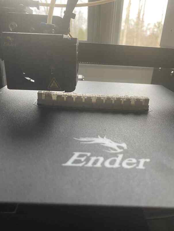
He then started the print again, and it worked.
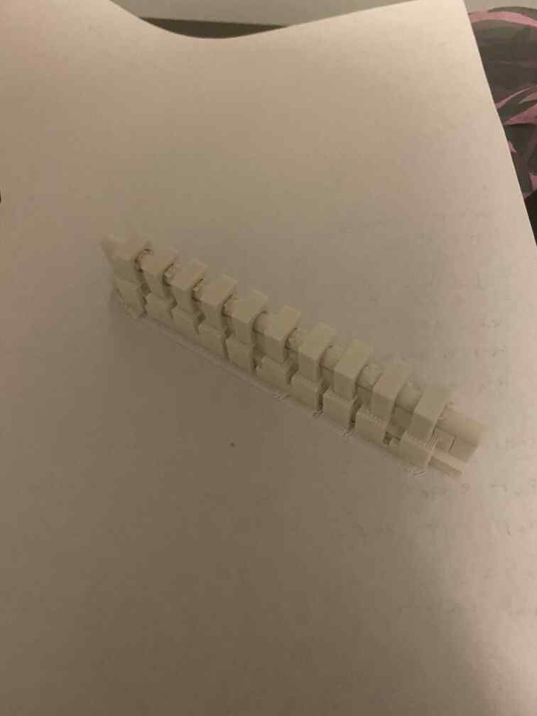
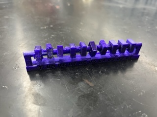
He then removed the supports and saw which parts could be moved.
Everything but the 0.2 and 0.1 clearance could move, but the 0.3 moved only with resistance, so functionally, the clearance should be 0.4.
Prusa Lab Printers
**SIDE NOTE: WILL ADD THE IMAGE FILE DIRECTORIES JUST CANT RN BUT I WILL SOON SO ATM IT IS JUST TEMPORARY NAMES FOR THE IMAGES
Nick printed the same clearance file but on our in-lab printers. I ran the file through Prusa Slicer then uploaded that gcode to the printer through our web server that links all the printers.
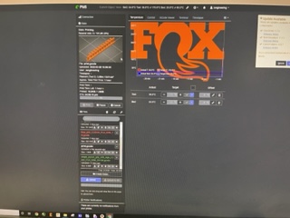
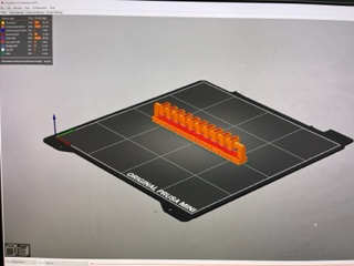
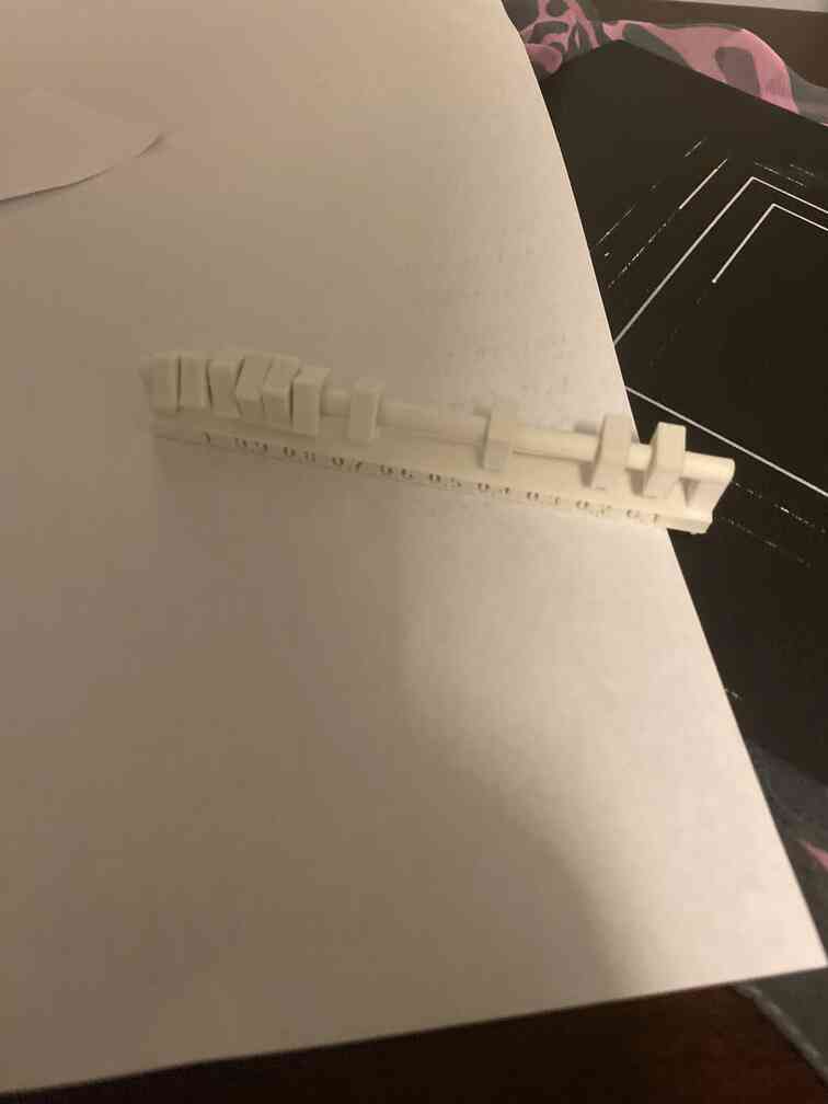
Then all I had to do was wait. It was a very simple process. The first time I ran it, it for some reason didn’t sent with supports and the print turned to spaghetti towards the overhang part. I went back to Prusa and toggled supports to everywhere and reuploaded that gcode. This time, it printed with success in about an hour and a half. Here is the final product:
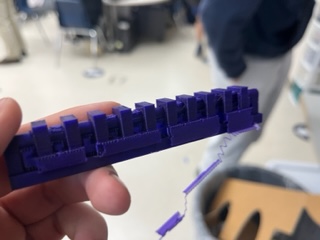
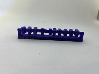
Removing the supports was a long and tedious process but I eventually got most of them off and could test the clearance of our Prusa’s. What I found was only the 0.3 mm and below pieces couldn’t move and the rest could, meaning the clearance wasn’t less then 0.3 mm. This is useful to know as it shows that the ender printers at home are better for more accuracy.
Resin Printers
Finally, Nick and Alaric together worked on setting up and analyzing the resin printer’s result from that same clearance file.
They first pulled up the file in PreForm and added supports then sent it to the printer.
They then made sure that the bed was clean and started the print. Alaric then came in and moved it to the alcohol wash. Later, he moved it to the curing machine.
Afterwards, Alaric and Nick worked together on removing the supports, but there were some inside of the loops, which proved too difficult to remove, so the test did not work for the resin printer as a result.
Infill Andrew and Aarush
This week, Andrew and [Aarush](https://fabacademy.org/2022/labs/charlotte/students/aarush-vemuganti/assignments/5.3DScanningAndPrinting/ worked on characterizing the infill of 3 different printers: the personal Creality Ender 3 V2s, the Prusa Minis, and the resin printers. Infill refers to the interior density of the created 3d prints infill plays a role in a prints strength, structure, and weight, so it is important to keep in mind while printing. Both Andrew and Aarush tested on all three printers over four different settings for infill: 0, 15, 50, 100. Aarush was tasked with printing 0% infill and 50% infill while Andrew was tasked with printing 15% infill and 100% infill.
They both first downloaded the infill stl file off of this week’s Fab Academy assignment page, then used different slicing softwares for each printer.
Ender 3
For the personal Ender 3 printer, Andrew, who was tasked with printing 15% infill and 100% infill, decided to use the Ultimaker Cura slicing software since it was compatible with many different printers including the Ender 3. He first brought in the stl file into Ultimaker, clicked on the print settings on the top right corner and selected “Custom”. He then changed the infill according to whether it was 15% or 100%, and clicked the “slice” button.
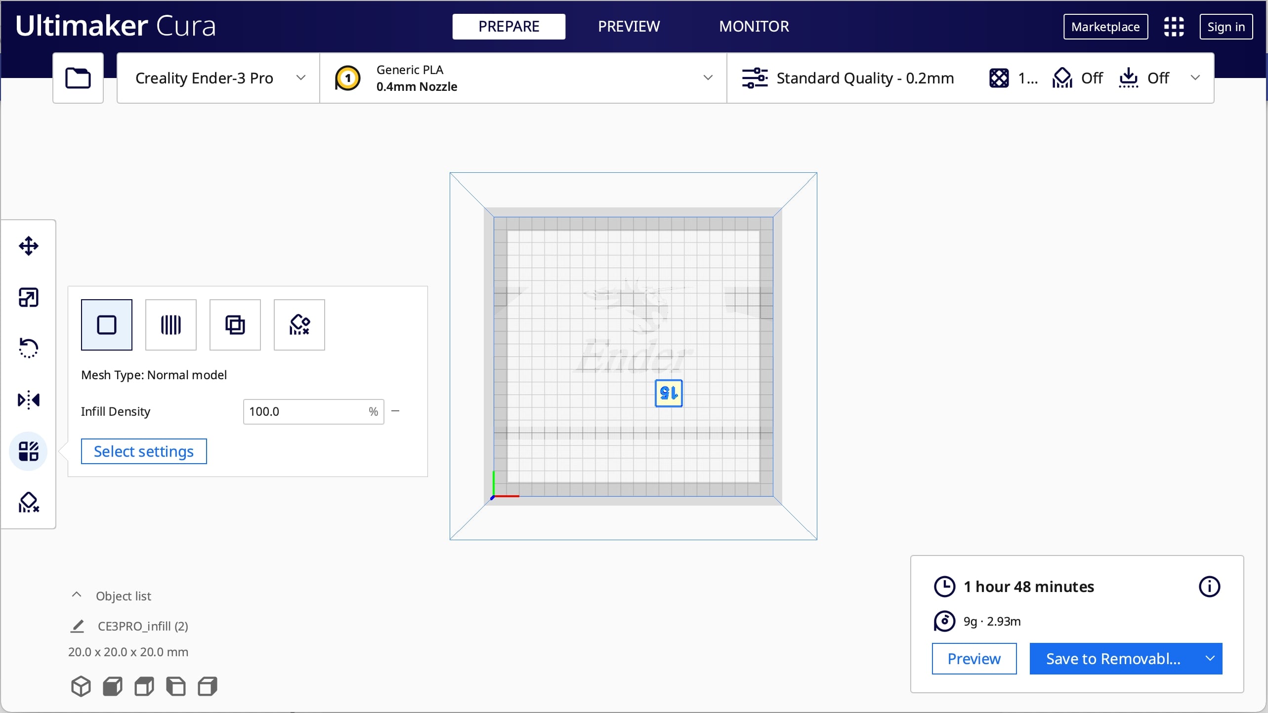
Andrew then saved the gcode file to his SD card, put it into the printer, and chose to print from TF.
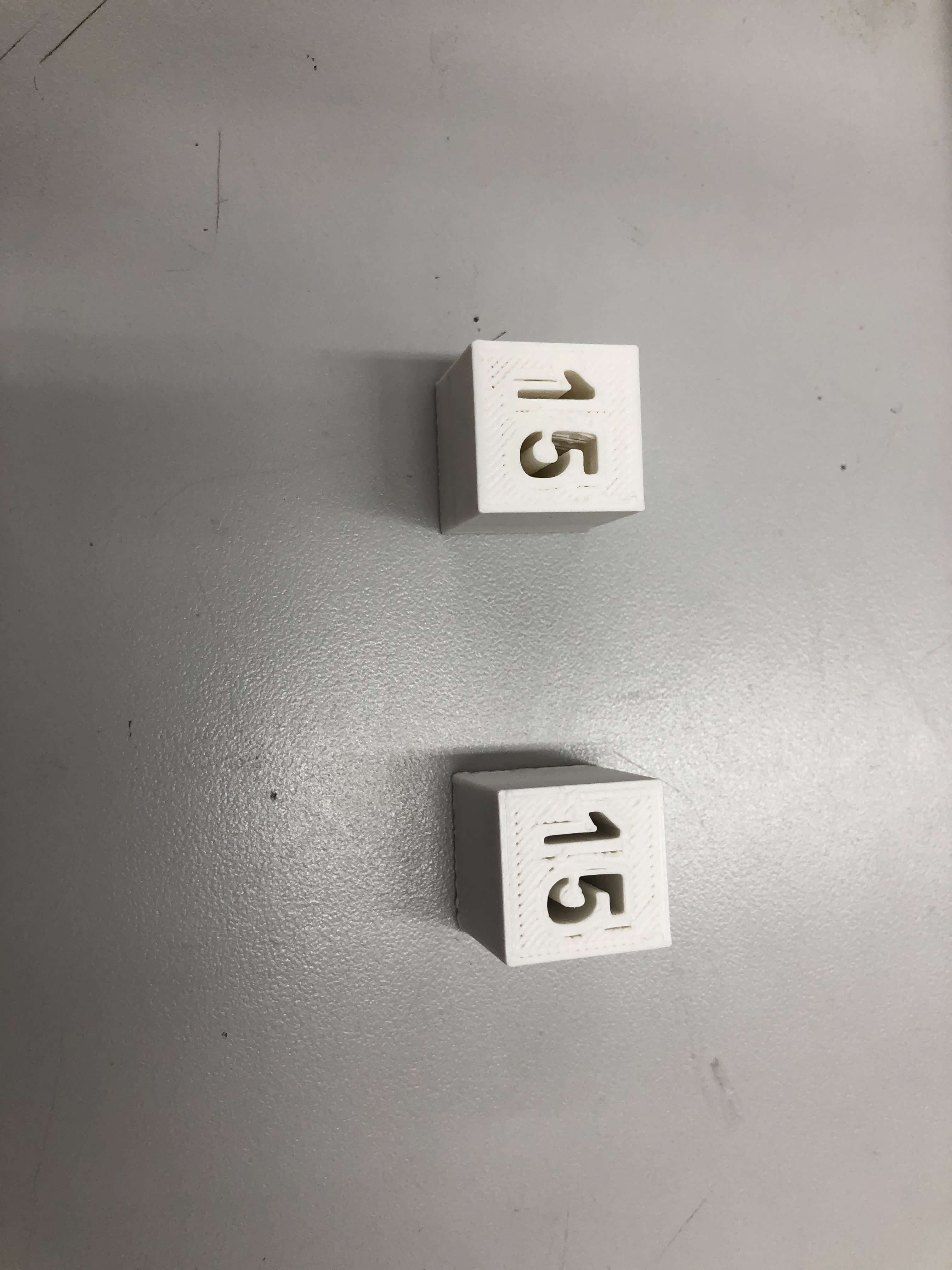
This is the final result for the cubes that Andrew printed
Aarush printed cubes with 0% and 50% infill on his personal printer. At first, he downloaded the Creality slicer since the Ender 3 printers were from creality. However, he did not like the user interface and thought it was a bit limiting. Instead, he decided to download PrusaSlicer which he had experience using in the lab. This is also where he found out how to change the infill settings for different objects on the same print. It seemed like it was not possible to chnage the infill settings for different objects on the Creality Slicer, so the PrusaSlicer seemed like a better software to work with. In order to change the infill on each object, first he imported the .stl files that he was using, then right clicked on the object. He scrolled down to the infill option near the bottom of the list. A menu opened on the left. From there, he selected the infill value which was at 15% originally and changed it to 0% for one of the prints. He then sliced it and saved the gcode file to his SD card so he could put it into the printer and print it.
Prusa Minis
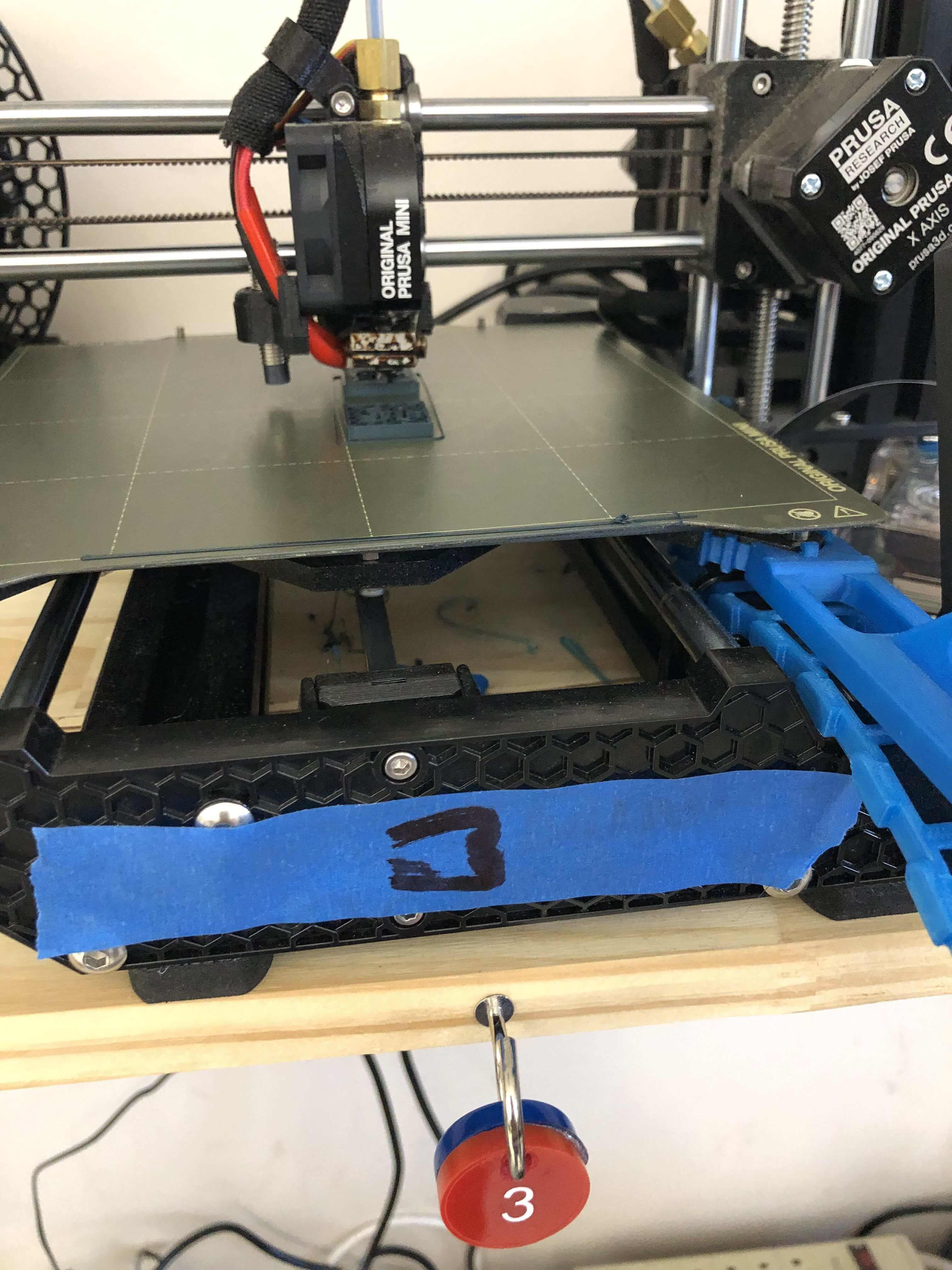
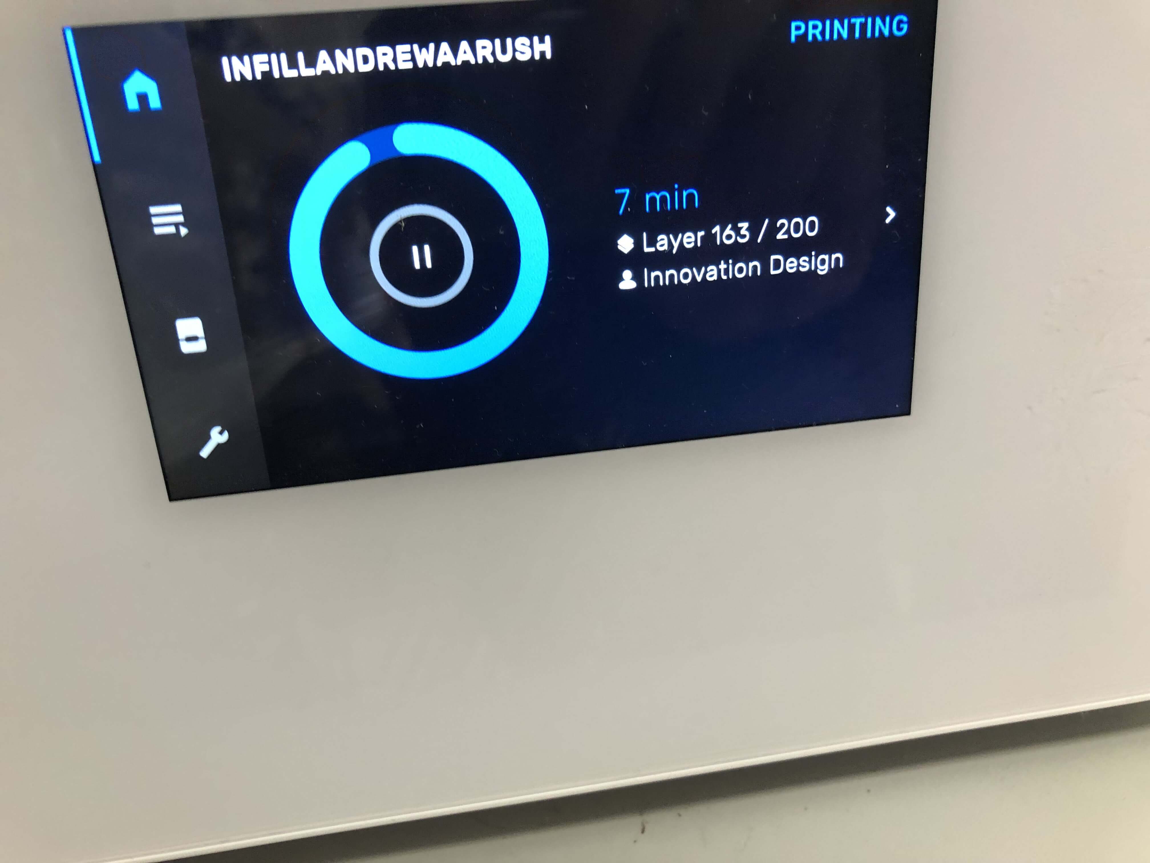
For the Prusa printers, both Andrew and Aarush worked together to slice the cubes. To maximize efficiency, Andrew ended up printing the 15% and 100% cubes at the same time that Aarush printed the 0% and 50% cubes. They both took their infill stl file and brought it into PrusaSlicer. As they wanted to print two cubes at a time, they both struggled to make sure each cube had different settings, since changing the infill would result in changing the infill for both cubes. Then, Aarush discovered how to change the infill for each individual file in PrusaSlicer, and they both sliced and then exported the gcode to the lab’s Prusa Minis via Octoprint. OctoPrint allowed them to remotely monitor the printers without having to be present.
Resin printers
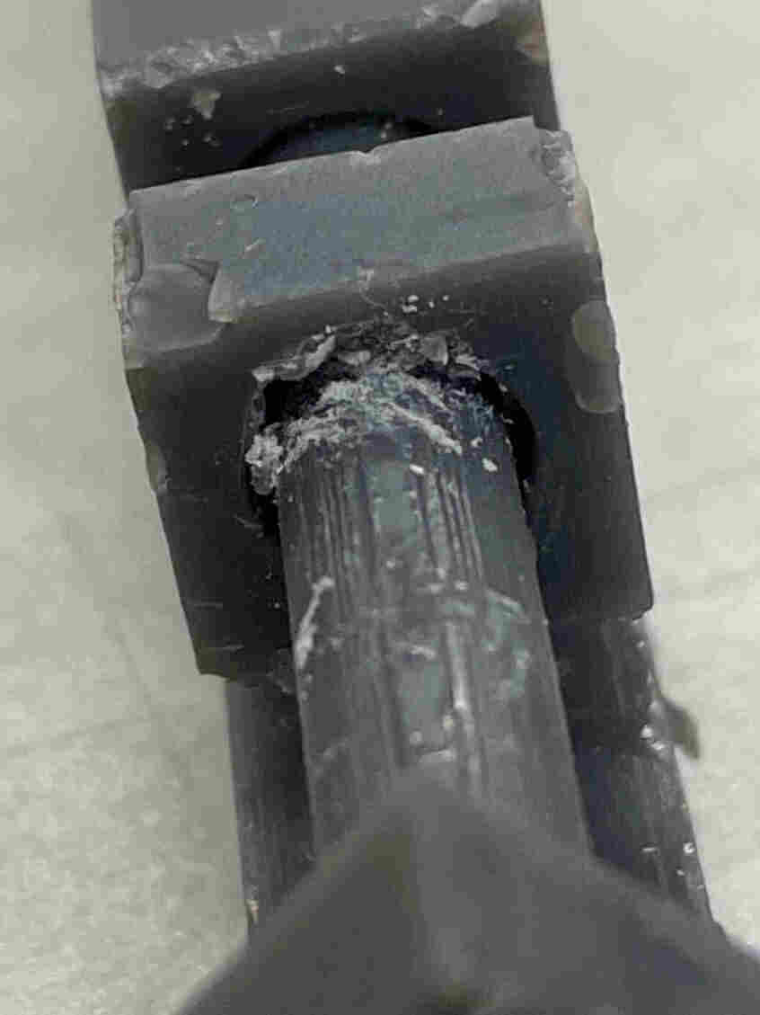
For the resin printers, it was mainly Andrew who worked on this print. Since he was unfamiliar with these printers, he was also assisted by Mr. B. The resin printers were a different kind of printer than the others, in that it wasn’t really a nozzle moving around and depositing plastic layers. Instead it had three phases: print, clean, cure. Andrew started by importing the stl file into the PreForm slicer. He was then informed that the software didn’t have infill settings since all the resin printed infills were the same. Still, he wanted to test out the resin printers, so he went ahead and printed four test cubes anyway.
Andrew first plugged in the printing station and went through the preprint process which was fairly simple. Then came the actual printing, which he didn’t have to do much for. Andrew simply just told it to print on the printer screen.
Next, after the print finished, Andrew removed the bed from the printer and placed it into the alcohol station. He then turned this station on, and told it to run, which took about 20 minutes.
After the time was up, Andrew came back and put on some protective gloves. He carefully removed the bed from the alcohol, and used a sharp edge to separate the cubes from the print bed. He then placed the cubes in the curing station, which just seemed to use UV light to smooth out the resin print.
Summary of results
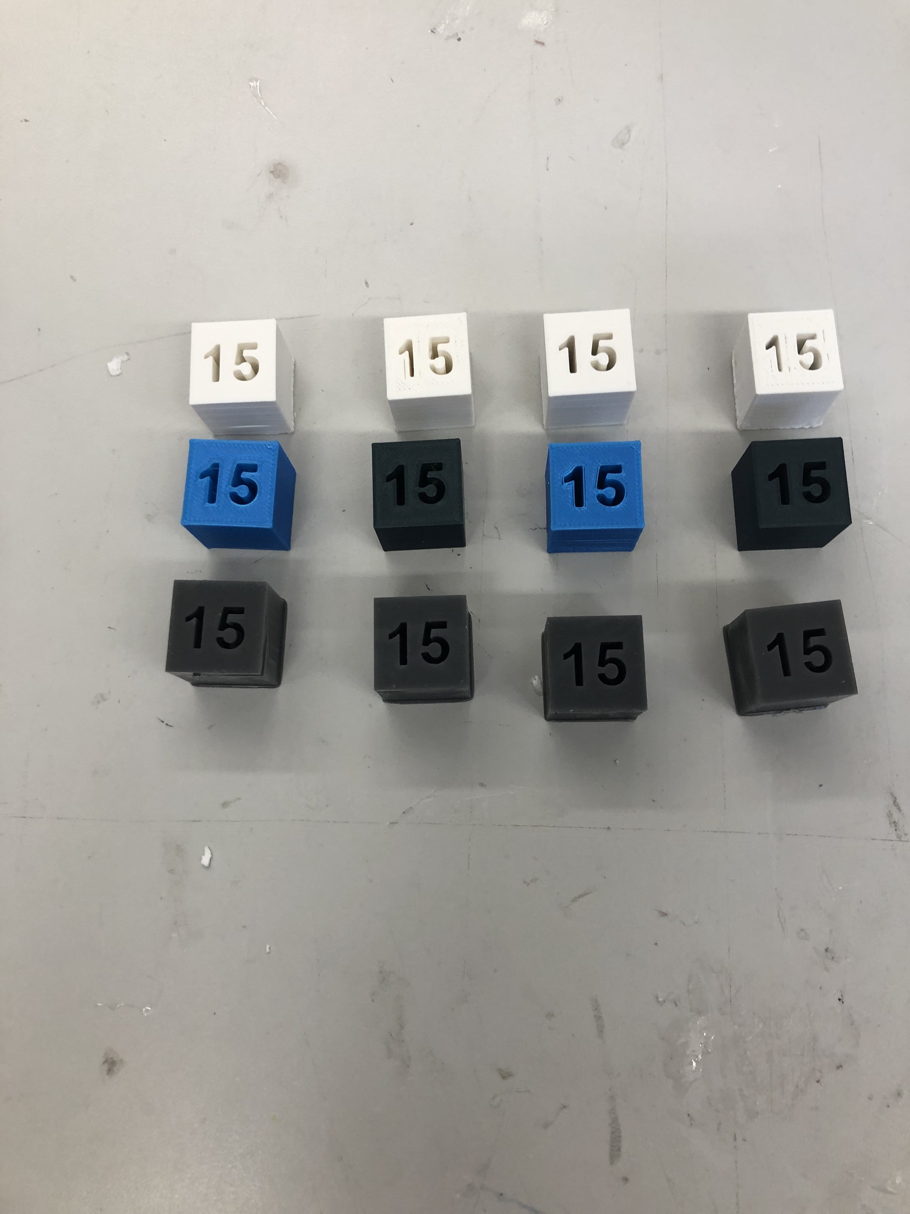
Overall, this week’s infill prints turned out fairly well, and you can feel a noticeable weight difference between the 0% and the 100% infill cubes. Our conclusion from these tests is that as the infill increased, so did the print time, but also the strength and weight of the cube. An optimal infill setting thus depends on what the print is for; if it needs to be a quick print and you don’t care about strength, then low infill values are better. The opposite is true for higher infill values.
Infill File
Click here to access to infill file
Jada and Pari
Prusa 3D Printers:
To test the overhand of the Prusa 3D printers which were located in the Charlotte Latin Fab Lab.
Ender 3 Pro:
I downloaded this file:
FILE
From the [Fab Academy] assignment page for this week and used it to print onto my personal Ender 3 Pro Printer at home. I downloaded the file as an stl then added it onto my printer’s flash drive. After I added it to the drive I removed the SD card and inserted it into my printer. I clicked: Print from TF on my 3D printer and the print started. It went pretty smoothly but the only small problem was the support strength. The supports again were a little too strong but the overhang itself went decently well.
IMAGE
Formlabs Resin Printer:
[Jada] and [Pari] tried to print the overhang file on the Formlab resin printer but whenever we positioned it right side up the computer would automatically flip it back upside down. We thought that is just how we were supposed to have it but when it is upside down there is a crazy amount of support on it.
IMAGE
We started to print but stopped after we realized that this overhang file on the resin printer was a huge waste of resin and a lot of money down the drain spent mostly on supports of the design. We realized having this type of test on the Resin printer was pointless and a waste of materials so we stuck to the actual 3D printers.
Files
The files we used are located here files