Week 6. 3D Scanning and Printing (Feb 22)
Week 06 Assignment
-
design and 3D print an object (small, few cm3, limited by printer time) that could not be made subtractively
-
3D scan an object (and optionally print it)
3D Printing
Building, Wiring, Calibrating, and Testing the Printer
Before Fab Academy even began, I received the kit of parts for my vey own Creality Ender 3 v2 3D printer. Our lab’s instructors Dr Taylor and Mr Dubick advised us to start building our printers as soon as possible so that we would have a head start, and not have to do as much work for the 3D printing and scanning week. Following their advice I immediately began to work on building my 3D printer by following this CHEP tutorial referred to me by Mr Dubick.
To start I opened up the cardboard box containing all the components, which looked like this.
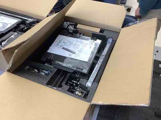
I then took out the actual instructions for building the printer out of the box, and checked to make sure I had all of the components and that I wasn’t missing any. I ended up having all the components, but the reason there aren’t check marks on each component on the paper in the image is because I had forgotten to check those ones off before I started. Although it ended up working out this time, next time I will check off all of the components on the paper so that I am absolutely sure that I have all the components before I start building.

Note: I used a combination of the official build instructions and the CHEP video’s instructions for the build, which don’t match what’s written on the paper. I did this because of two reasons; 1) the CHEP video process seemed much more straightforward, and 2) my fellow student Mrs. Dhiman said that the video was a lot easier to follow than the ones on paper. I ended up using both however since there were some things the guy in the video didn’t mention, such as which type of screws would go on which component. For these kinds of things I would have to find the step on paper and reference that. After taking the components out of the box, I found the main bed, which looked like this.

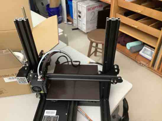
I flipped the bed over, and found that it was very wobbly. Also, I noticed that one of the gear wheels was missing from the bottom of the bed. Luckily, I dug around in the box and found the wheel and spring, and then screwed them back in. Then I continued with the video, and used the wrench to tighten the bed. Once the bed was tightened I then used the allen wrench and the M5x45 screws to mount the left upright in. Then I mounted the stepper motor, stop switch, and extruder. Next I slid the threaded rod in, and mounted the belt for the horizontal bar. At first I had stuck the belt on the wrong way, but then I realized it when looking at fellow student Aarush Vermuganti’s build and simply flipped it the other way. I mounted on the horizontal nozzle, the switch, the right upright support, and the top crossbar. At this point this is what the printer looked like.
Finishing off the printer, I then mounted on the battery pack, cut the zip tie, and stuck the PTFE tube into its hole on the extruder. Finally, I mounted on the screen to the front right corner of the printer, and I was done with the actual mechanical building portion.
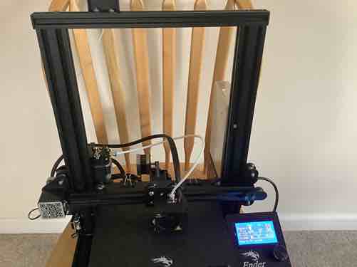
At home I finished up the wiring, which I continued following the video for. I plugged in the power supply to its designated yellow ended cable, and then took the rainbow connector and plugged it into port EXP3 on the back of the screen. I then plugged in the X switch, X stepper motor, and extruder into their respective slots. Using an allen wrench, I flipped down the voltage setting to 115, and plugged in the power cable into a wall. My printer was fully built and wired, and this is what it looked like.
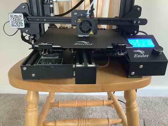
The final steps were to calibrate my printer, feed the filament, and make sure everything worked. I tried turning on the power switch, but found that my printer didn’t work. I checked all the wire connections and realized I had forgotten the z switch wire. After plugging it in, my printer turned on. I clicked on the button, went under the prepare menu, and clicked auto home, which calibrated each one of the switches in the x, y, and z directions.
After auto homing, the final step was to feed my filament through the exxtruder into the PTFE tube. The first time I tried it, I couldn’t get the filament through the hole to the PTFE tube, and I spent tons of time trying and trying to get it in with no luck. Since the CHEP video didn’t mention feeding the filament, I searched for some other tutorials. I found this one by 3D Printing Canada to be particularly helpful.
The tutorial showed me three additional things to do 1. Use the pliers to cut the filament at a 45 degree angle 2. When feeding the filament in, press on the spring to free up space 3. Bend the tip of the filament downward so it can easily go into the tube
I found success feeding my filament, and slid in the wire until it bottomed. This just goes to show that sometimes you need multiple resources that show different things. My printer was fully operational, but there was one thing I had completely forgotten to do, which was level the bed. Because I thought my printer was completely working, I decided to test it out by printing something. I found the SD card in a white case, and plugged that into the printer. I then selected the dog-2.5hr gcode file and ran it. I was expecting it to print out a dog, but this is what happened instead.
I stopped the print a few minutes in, but as you can see, the print of the dog did not work because the plastic came out stringy and weak, giving the print an unintended lattice shape. Later, I found out that this was because of an uncalibrated bed, but this time I noticed that the filament had actually stopped coming out of the nozzle. After tracing the sourcing of the issue, I realized that my roll of filament had completely disconnected from the filament inside the nozzle, meaning no new filament was being fed and thus none was coming out. I surmised that this was because of the way my filament was placed and not an issue with the printer itself. I found this website to be helpful, and followed the instructions under the “Filament Bending & Too Much Spinning Movement From Spool” section. Since I was using the default filament that came with the printer, I didn’t get one of the wheels that were supposed to help regulate the spinning motion of the filament, and I was just having my filament hang from a nearby chair. To solve this issue, I put my filament on a light post object, which allowed spinning but not too much. After refeeding the filament in, I decided that the dog was too complex for a test print, and so I just started test printing my infill cubes for my group project. This is what happened the first time.
With this failed print, I finally remembered that I had to actually manually calibrate the bed height using the 4 wheels under the bed. To absolutely make sure I would get it right, I pulled up the CHEP video again as well as the documentation of fellow student Alaric. Both instructed me to first use a sheet of paper on the bed, and twist the wheels until the nozzle applied pressure to the paper but you could still move it around. I repeated the process with all four corners, then retested the infill cube which then finally worked.
Finally, I got a 3D test print on my self built Ender 3 V2 printer working. Although there were many mishaps like my filament snapping or my bed not being levelled, I still learned a lot about debugging 3D printers. I definitely won’t he making these mistakes again on my next print, and even if I do, I now know how to fix them.
Rotating Rings Toy
For the actual assignment of the week, we had to create a small object that could not be made subtractively. At first, I didn’t really know what that meant, but I got further clarification from three sources. 1. Neil’s lecture 2. Two articles on subtractive and additive processes from the fab 3D printing and scanning week page 3. Dr Taylor’s fab print - a ball inside of a cage
After looking at these sources I finally got what additive and subtractive processes were. An additive process is when you are creating things, adding on layer by layer until you get your finished product - a “producing” process. A subtractive process is when you are taking a block of something and then shaving off the excess to get what you wnt - a “cutting” process. However, a subtractive process usually produces more wasted material, while additive processes take much longer to do. For example, a 2 1/2 hour print may only take about 5 minutes on the laser cutter, but waste much more material. Thus, an object that cannot be made subtractively is simply something that could not be made by taking away material. After understanding this concept, I went to look for ideas of what to print.
I started off looking on previous Fab student Teddy Warner’s site for inspiration and saw that he did a case for his PCB from the electronics production week. I wanted to do something different from the other people, so I went onto Thingiverse and searched “rings”. Sure enoguh, I found this rotating ring toy that could not be made subtractively since the rings had to be already meshed together. I decided it was the perfect object to print and got working on the design.
Since I have design experience from Week 02 and engineering classes, designing the rings wasn’t too hard to do. Also, this video tutorial on how to design gyroscopic rings I found was very helpful.
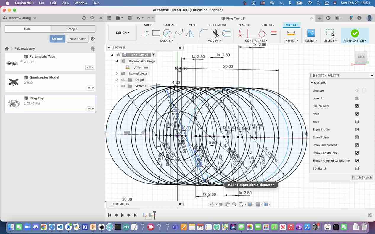
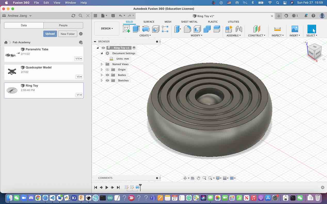
To start, I opened up a new Fusion 360 and put a sketch on the front plane. For this design, I used parameters in order to make designing the rings easier and more scalable. I created 4 parameters for the 1st and 2nd ring widths, the center ring diameter, and the helper ring diameter so that I could change the sizing of my rings with a single dimension

Then I followed the video to create numerous 20 mm circles and a 10 mm circle, which were either spaced 2 mm or 1.5 mm apart. Then my finished sketch looked like this.
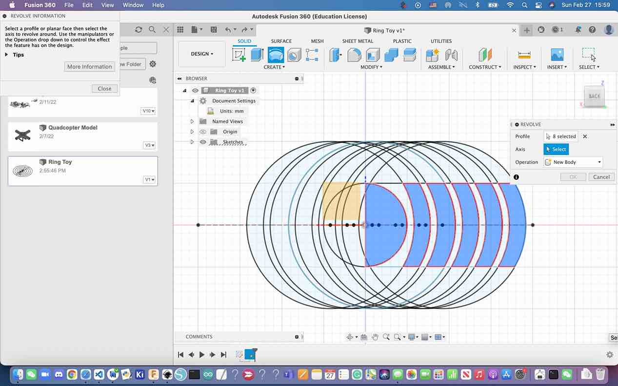
Next I finished the sketch, and opened the revolve menu. I selected the semicircle and the pod arcs for the profiles, and selected the radius of the circle for the axis. This is what it looked like.
After pressing ok, this is what the finished design looked like.
Now it was time to print. I simply exported the Fusion Obj file as a .stl file by hitting File -> Export, bringing up the export menu. I selected .stl file and hit the export button, which successfully converted that .obj file into a .stl file.
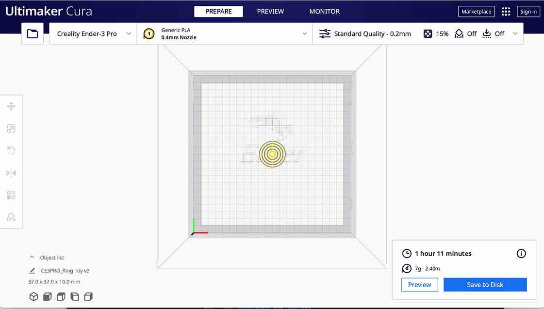
Then came slicing, which I decided to use Ultimaker for. I went to the Ultimaker website and selected Ultimaker Cura, which was the slicing software that was compatible with many different kinds of printers including Enders. After downloading the slicer, I choose the printer that I was using, the Creality Ender 3, and selected the default settings. Then I brought in the .stl file from before, and clicked the big blue slice button in the bottom right hand corner. This was the final view of the slice.
I stuck in the SD card once again, and simply moved the newly created gcode file onto the card. Then I unplugged the card and used the same process that I had used for the infill cubes to print it out. First I turned on the printer, and auto homed the x, y, and z directions once again. Then I went back to the info screen, clicked once, went to Print from TF, and selected the ringtoyv1.gcode file. Luckily, my print worked well enough that I didn’t necessarily have to print many more times. The reason I was able to get it working on pretty much the first try is because of my prior failures when testing, calibrating, and building the printer. I had taken the lessons I had learned from that, and applied it onto the actual assignment print. Not only am I proud of my print, but also the struggles and lessons I learned along the way.
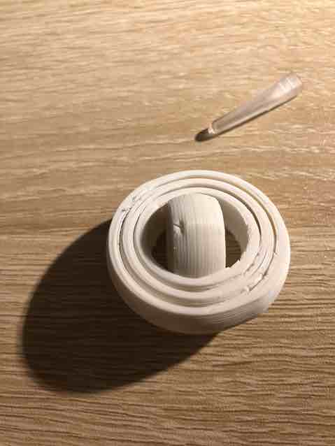
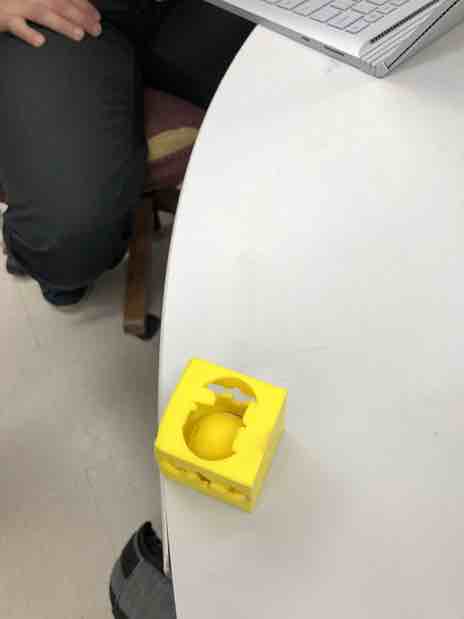
This is what the print ended up looking like. As you can see, it is a print that could not have been made subtractively because each ring has to fit inside of each other, and there is a ball in the center that was printed inside of that ring.
3D Scanning
Meshroom Exploration
This week for 3D scanning, our assignment was simply to 3D scan an object. At the beginning of the week, I did some research on photogrammetry, which is the process of taking tons of pictures and importing them into a software that then converts these pictures into a complete 3D model. After I had watched Neil’s lecture, I was intrigued by the photogrammetry software Meshroom. I went onto youtube and found this tutorial on how to use Meshroom with just my phone camera, and even wrote up a basic workflow for it.
Basic Meshroom Workflow
- Standard Reconstruction
- Copy all of the pictures to a folder
- Drag and drop the pictures/folder into Meshroom window
- Save the project to a destination
- Hit Structure from motion and hit complete
- Compute full reconstruction if all the pictures are checked
- Click the texturing node at the top
- Augmented Reconstruction (After steps 1 - 4 from standard reconstructions)
- Take 5 to 10 more pics
- In the 2nd bar, compute the structure from motion node
- Hit complete
After I had created this workflow, I went onto the actual Meshroom site, where I read through all of the tabs. Trying to find a download button for Macs, I realized I had made a mistake, since Meshroom was actually not compatible with Mac OS (something I found out through googling it). This meant I had essentially wasted a considerable amount of time researching Meshroom when I couldn’t even use it. However, it wasn’t really a complete waste, because I began to understand the process of photogrammetry and scanning more.
Qlone
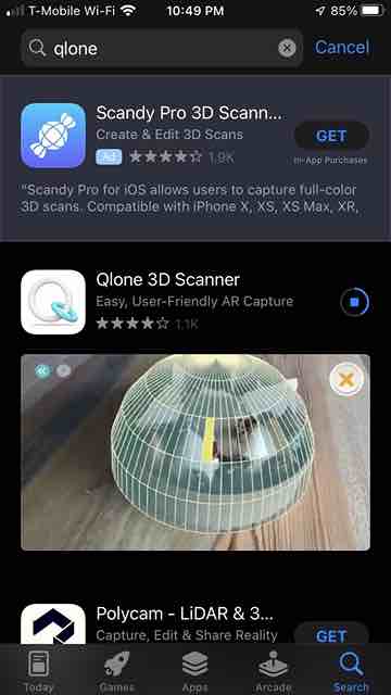
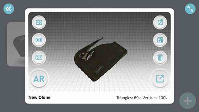
After this revelation, I decided to opt for simplicity and use Qlone, a simple phone scanning app that uses an AR (Augmented Reality) display and a scanning mat to recognize objects. I immediately downloaded the free Qlone app onto my phone
After I had the app downloaded, I opened it up on my phone. I clicked on the plus button to start a new scan, and this was the popup.
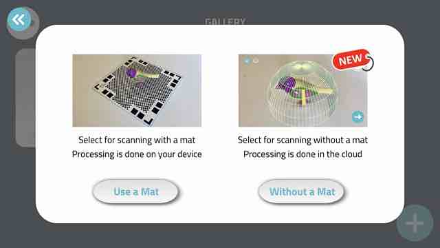
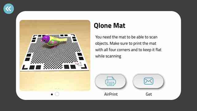
As you can see, Qlone works by only detecting objects that are sitting on top of a specific cutting mat. I couldn’t use the Without a Mat option since that was behind a paywall, and I didn’t see the point in paying for such a feature. Thus, I went to the dropdown menu, selected cutting mat, and this popped up. I choose to print out the cutting mat.
After having the printed mat, I could finally start scanning. I grabbed the nearest object that was small enough to fit on the mat, which happened to be a mail opening knife. I clicked the plus button once more, and selected use a mat. Then I held the phone over the mat with the knife on it.
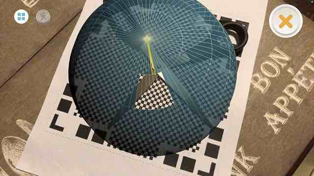
As you can see, the Qlone AR interface works by having a blue shaded sphere around your object. You use your camera to highlight a specific chunk of the scan, then as you move the phone around in different configurations, the blue sections gradually go away. Once all the blue has been removed, the softare has to process the scan.
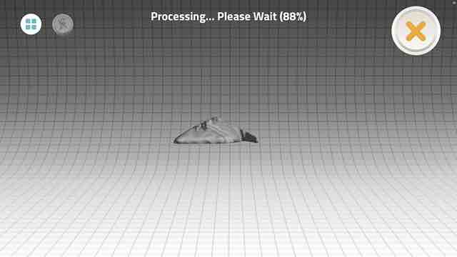
This was the result of my first scan, which wasn’t that great. This first scan I did was on a relatively flat object, and so the height in the middle parts was kind of distorted and resembled a pyramid instead of a flat surface. This may be a limitation of the Qlone software, that scanning objects with too little thickness results in some funky mistake. It’s also possible that I was going too fast and inaccurate in the AR interface, and that’s what messed up the scan.
Following the exact same process, I redid it with a different object this time. The sketch came out better, which could indicate one of two things. Either it was a problem with the object I was scanning previously, or it was a problem with my scan itself.
EIther way, I am very proud of what I accomplished this week. Not only did I gain a much better understanding of photogrammetry and the scanning process as a whole, but I also scanned my first object. Scanning is very helpful for when you have an object you want to 3D print, but don’t want to remodel it in CAD. I am sure that this will be very helpful for my final project, specifically scanning a propeller and just printing that instead of having to design a propeller like I did in week 02 with Onshape.
Week 06 Group Project
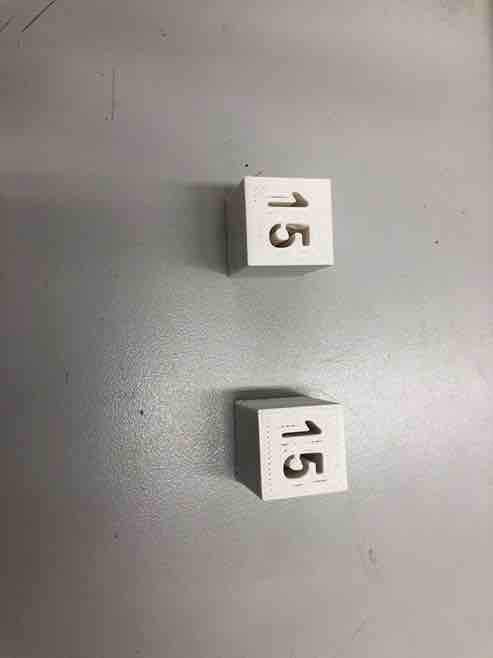
This week, Aarush and I worked on characterizing the infill of 3 different printers: the personal Creality Ender 3 V2s, the Prusa Minis, and the resin printers. Infill refers to the interior density of the created 3d prints infill plays a role in a prints strength, structure, and weight, so it is important to keep in mind while printing. Both Andrew and Aarush tested on all three printers over four different settings for infill: 0, 15, 50, 100. Aarush was tasked with printing 0% infill and 50% infill while I was tasked with printing 15% infill and 100% infill.
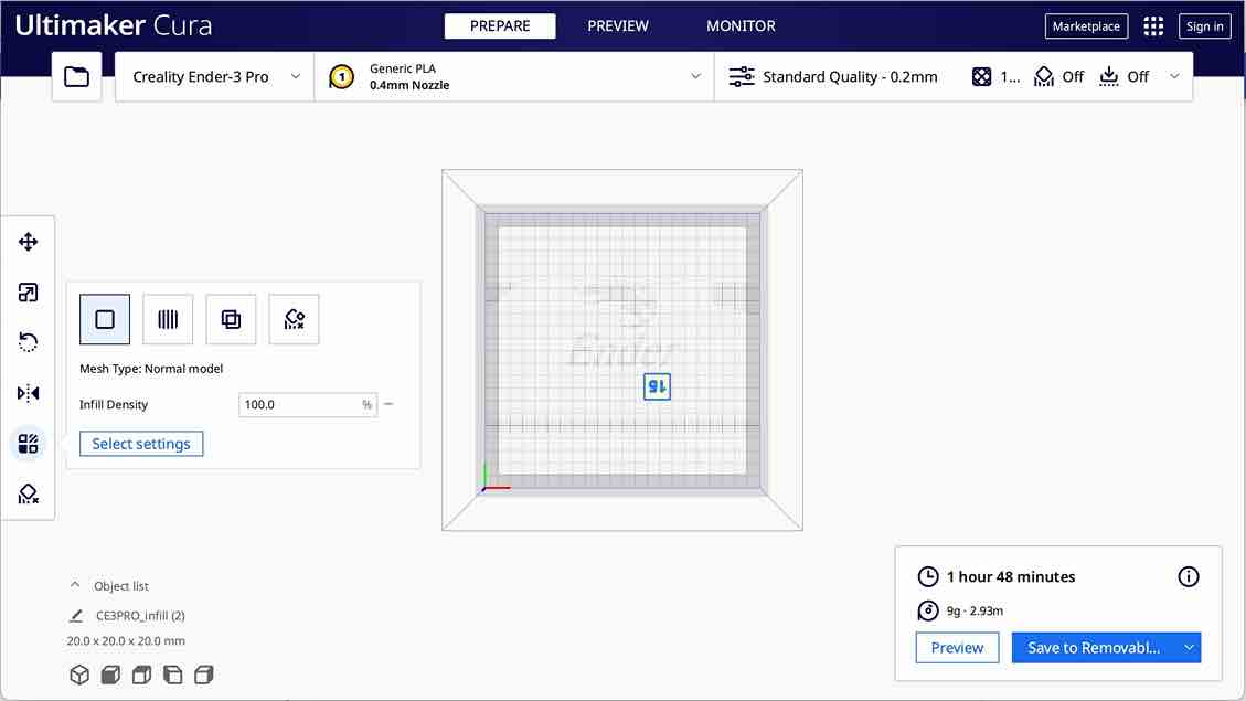
I first downloaded the infill stl file off of this week’s Fab Academy assignment page, then used different slicing softwares for each printer.
Ender 3
For the personal Ender 3 printer, I decided to use the Ultimaker Cura slicing software since it was compatible with many different printers including the Ender 3. I first brought in the stl file into Ultimaker, clicked on the print settings on the top right corner and selected “Custom”. He then changed the infill according to whether it was 15% or 100%, and clicked the “slice” button.
I then saved the gcode file to his SD card, put it into the printer, and chose to print from TF.
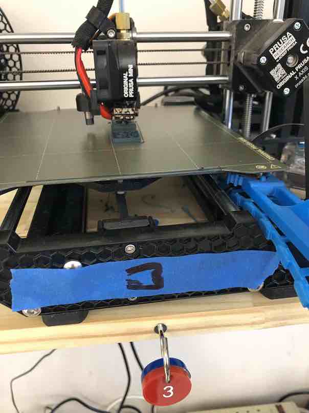
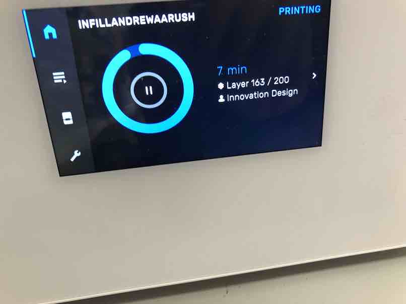
Prusa Mini
For the Prusa printers, both Aarush and I worked together to slice the cubes. To maximize efficiency, I ended up printing the 15% and 100% cubes at the same time that Aarush printed the 0% and 50% cubes. I took the infill stl file and brought it into PrusaSlicer. At first, I struggled to make sure each cube had different settings, since changing the infill would result in changing the infill for both cubes. Then, Aarush discovered how to change the infill for each individual file in PrusaSlicer, and I sliced and then exported the gcode to the lab’s Prusa Minis via Octoprint. OctoPrint allowed them to remotely monitor the printers without having to be present.
Resin Printers
For the resin printers, it was mainly I who worked on them. Since I was unfamiliar with these printers, I was also assisted by Mr. B. The resin printers were a different kind of printer than the others, in that it wasn’t really a nozzle moving around and depositing plastic layers. Instead it had three phases: print, clean, cure. I started by importing the stl file into the PreForm slicer. I was then informed that the software didn’t have infill settings since all the resin printed infills were the same. Still, I wanted to test out the resin printers, so I went ahead and printed four test cubes anyway.
Andrew first plugged in the printing station and went through the preprint process, just sending the gcode file to the printer. Then I simply just told it to print on the printer screen.
Next, after the print finished, I removed the bed from the printer and placed it into the alcohol station. I then turned this station on, and told it to run, which took about 20 minutes.
After the time was up, I came back and put on some protective gloves. I carefully removed the bed from the alcohol, and used a sharp edge to separate the cubes from the print bed. I then placed the cubes in the curing station, which just seemed to use UV light to smooth out the resin print.
Click here to access this week’s group site page.
Week 06 Files
Click here to access my files from this week