Week 5. Embedded Programming (Feb 15)
Week 05 Assignment
-
read the data sheet for your microcontroller
-
use your programmer to program your board to do something
-
extra credit: try other programming languages and development environments
Reading the datasheet
This week, one of our requirements was to read the datasheet for our microcontroller, which happened to be an ATtiny412 in my case. Here is the link to the datasheet for the ATTiny412. Since the datasheet is ~500 pages, I obviously won’t describe every single detail that I learned when reading, just the most notable portions.
One of the most helpful portions of the datasheet is the pinouts. The pinouts tell you which pins on each microcontroller perform which function, such as GND, VCC, and UPDI pins. This is an essential part of programming with microcontrollers, since if you don’t send data to the correct pin, then you can’t program anything at all. Here is a picture of the pinouts for the ATTiny412.
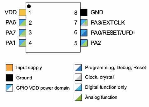
This is on page 13 of the datasheet
As you can see, the VCC or power pin is pin 1, GND pin is pin 8, and UPDI pin is pin 6. The other pins PA1, PA2, PA6, PA7, are meant for programming and connecting outputs to, which is why they have both analog function and GPIO VDD power domain. Another notable thing about the pinouts is pin PA3, which is a programming pin that also doubles as the clock controller. In a microcontroller, there can either be an external clock (crystal oscillator) or an internal clock source, which helps the microcontroller track timing. With the ATTiny, there is already a internal 16/20 MHz oscillator, but there is also an option to use an external oscillator. This means that the ATTiny412 is relatively flexible, making it chip that is very easy to program.
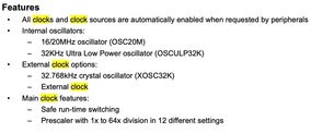
This is on page 56 of the datasheet.
Learning and Practicing Bare Metal Programming in TinkerCAD
This week, in addition to programming our microcontrollers to do something, our instructor Mr Dubick had all of our lab’s students learn about bare metal programming, mainly through using TinkerCAD. I’ve already talked about TinkerCAD in previous weeks such as Week 07: Electronics Design, so I won’t really go in depth over how to use it. Mr Dubick also created a slideshow that I followed to learn about bare metal programming. Here is the link to the presentation, which I pretty much followed step by step.
When I first began this week, I had never really done bare metal programming before, i.e talking directly to memory. However, I feel that this week has taught me a lot about the more “hardware” side of programming; not really programming to create games or collect data, but programming to tell an object to do something. Prior to the week, I felt that I had some experience with controlling hardware because of my robotics background, but I frankly had never delved this deep until this week.
In the presentation, I started by learning about the three registers that control each port: DDR, PORT, and PIN. DDR controls whether that pin is an input or an output, such as this Arduino code.
pinMode(ledPin, OUTPUT); // DDR responsibility
The PORT register controls whether the value of that pin is HIGH or LOW, such as this Arduino code.
digitalWrite(ledPin, HIGH); // PORT responsibility
The PIN register reads the value of INPUT pins, such as this code.
buttonState = digitalRead(buttonPin); // PIN responsibility
After we learned about registers, we then reviewed binary and decimal numbers.
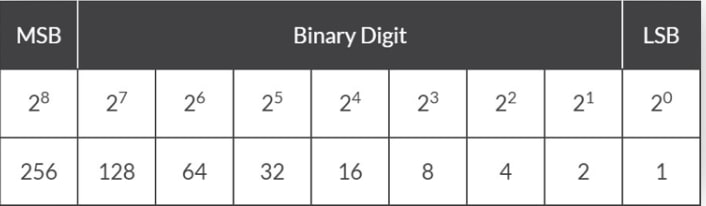
After reviewing binary, we began to learn about the registers on the Arduino. Mr Dubick showed us this diagram which was very helpful in figuring out the pins on an Arduino
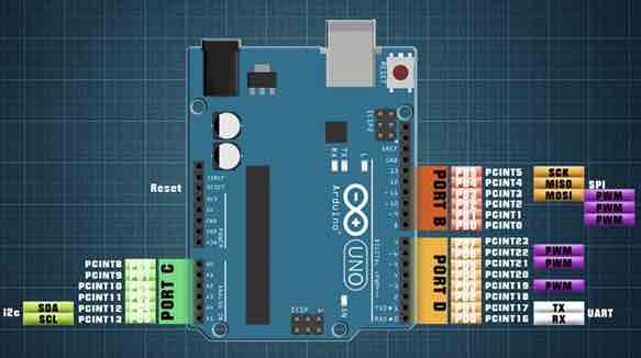
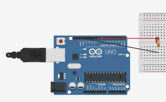
Then we opened up TinkerCAD and tried to use the PORT and DDR registers to blink an LED on pin 9 of the Arduino. I wired up the circuit like this using an Arduino Uno, breadboard, 1 kOhm resistor, LED, and wires.
For the coding of the circuit, my strategy was to use the basic blink code and build off of it using the registers. This was the basic pin 9 blink code that worked.
// C++ code
void setup()
{
  pinMode(LED_BUILTIN, OUTPUT);
}
void loop()
{
  digitalWrite(9, HIGH);
  delay(1000); // Wait for 1000 millisecond(s)
  digitalWrite(9, LOW);
  delay(1000); // Wait for 1000 millisecond(s)
}
After getting the basic blink to work, I then moved on to using the PORT register. From the previous diagram of the Arduino pinouts, I could see that pin 9 was really pin PB1. Then I swapped out the digitalWrite commands with the PORTB variable and set it to a value of 00000010 in binary, or 2 in decimal. I found success. Finally, I swapped out the pinMode command with the DDR register, which I set at 2 since that was the PORTB pin I was using. The code looked like this.
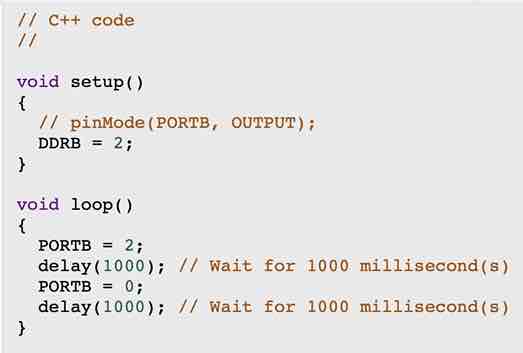
This was the result of the TinkerCAD experimentation.
Programming ATTiny412 MVP Board
This week, our main assignment was to use our programmer to program our board to do “something” - and that “something” in my case was going to be two things: blinking LEDs and integrating the pushbutton to turn the LED on and off. My goal this week wasn’t necessarily to write and test the most complicated code in one environment and call it a day, but use the blink example and pushbutton code in a variety of different coding environments to learn how to program in these specific situations.
Note: For this week, I halfway used a SAMD11C programmer board to program, and halfway used an Arduino Uno to program. This is because I had lost my SAMD11C board, and had no other choice but to turn the Arduino Uno into a programmer and do it that way instead. I have since remade a working SAMD11C programmer, but for the purposes of this week most of my coding is doene using an Arduino programmer
Arduino IDE
SAMD11C Programmer with Pushbutton Code
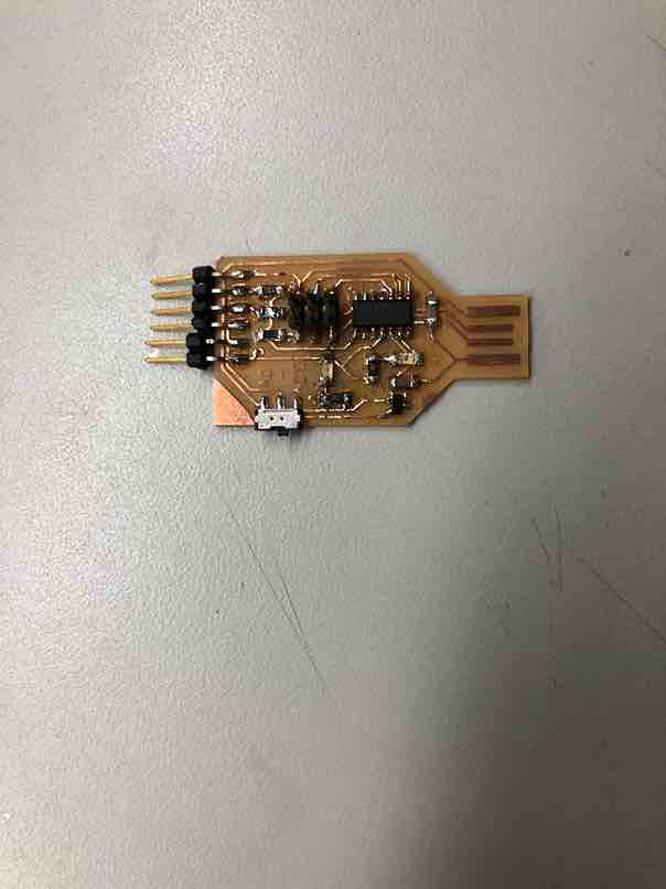
This is the MVP board that utilizes an ATTiny412 I made last week in Electronics Design.
I took the TinkerCAD example code and modified the pin numbers to fit my board since I was not using an Arduino but an ATTiny412. I referred to this ATTiny412 pinout sheet to figure out which pins to flash the button code to. Now it was time to actually set up the Arduino Tools settings.
I first downloaded the mattairtech library, allowing me to access the SAM family of boards
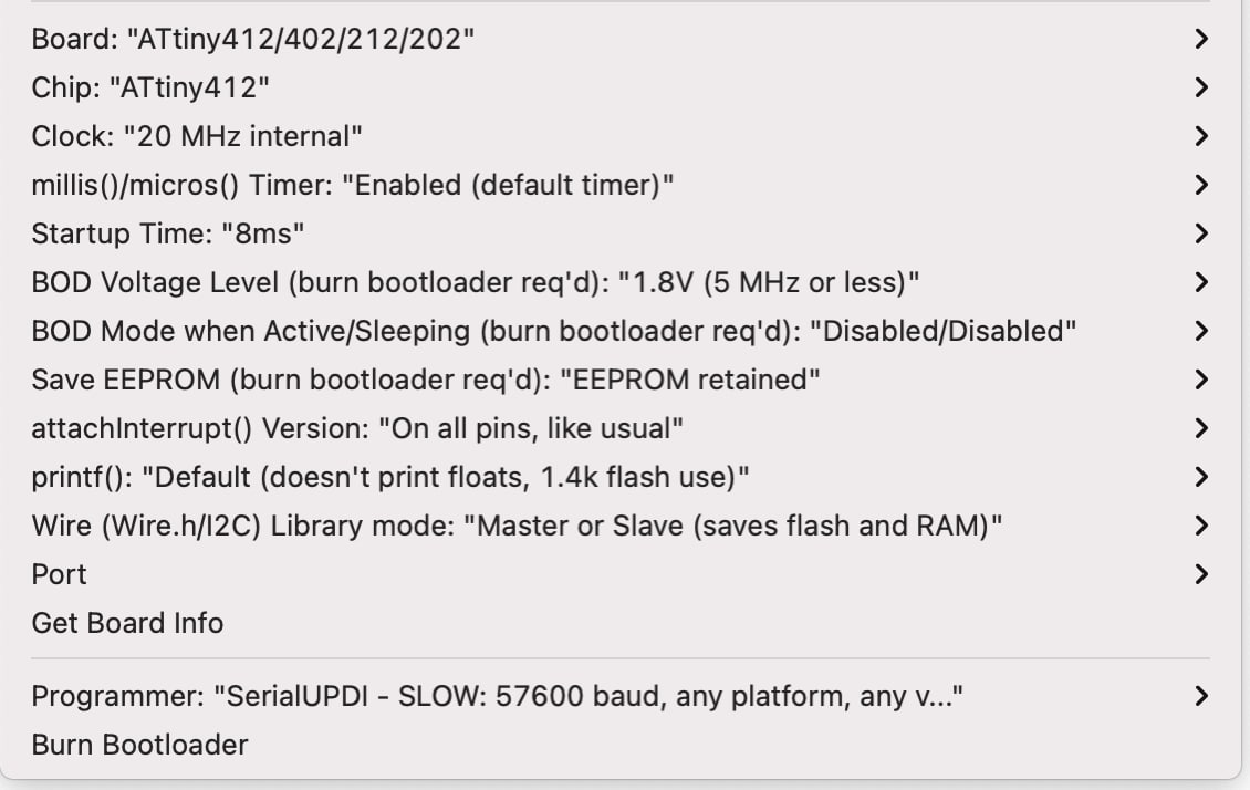
Then I went into a new Arduino file and called it the SAMD pusbutton code. Next, under the tools dropdown menu in the file, I went to board and selected the ATTiny412. Going down to programmer, I made sure the SerialUPDI - SLOW: 57600 Baud was selected.
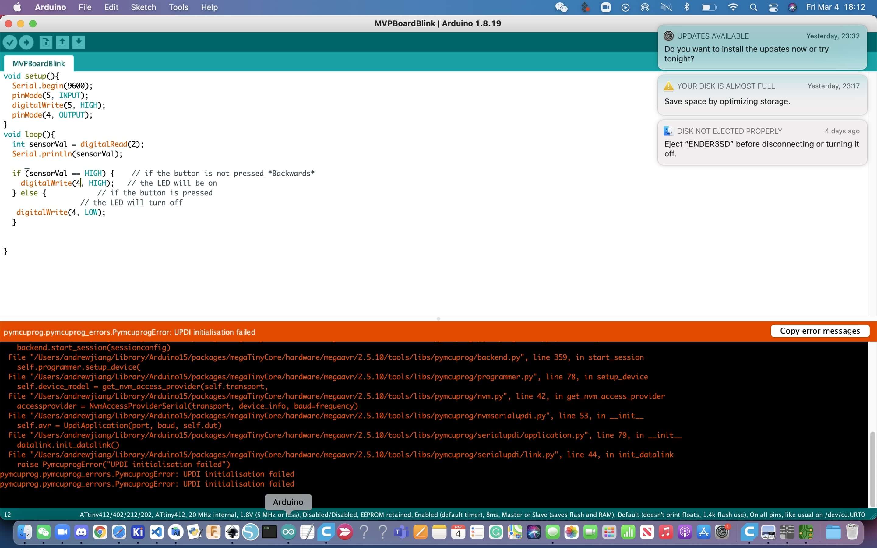
Onto the actual coding part, at first I kept getting this error when flashing the code to pins 4 and 5.
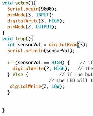
Then I realized my mistake, which was that I was using the wrong pins. Instead of using pins 4 and 5, I should have been using pins 2 and 3 instead. When I switched the code, this is what the code looked like.
void setup(){
  Serial.begin(9600);
  pinMode(3, INPUT);
  digitalWrite(3, HIGH);
  pinMode(2, OUTPUT);
}
void loop(){
  int sensorVal = digitalRead(2);
  Serial.println(sensorVal);

  if (sensorVal == HIGH) {    // if the button is not pressed *Backwards*
    digitalWrite(2, HIGH);   // the LED will be on
  } else {            // if the button is pressed
                  // the LED will turn off
   digitalWrite(2, LOW);
  }


}
This is the output from the working UPDI code

This proves that my board works.
Arduino Programmer with LED Blink Code
This week, I also experimented with using the Arduino as a programmer to program my MVP Attiny board to do various things. One of those things, was to make the LED on the board to blink. While getting an LED to blink may seem like a very simple process, it takes some effort to get yourself setup to be in the position where you can blink the LED. Before I started Fab Academy, I definitely underestimated the importance of blinking a simple light. As the weeks progressed, I have began to learn to appreciate and celebrate any success, even something as seemingly trivial as blinking a light. To be able to blink the LED using the Arduino as a programmer, I took many small steps forward so it was easy to track any errors if they happened.
The first step was to actually make sure the Arduino itself wasn’t faulty, since I have that happen before where I’ve wired everything correctly, gotten the right code, but simply used a bad board, and I wanted to learn from my mistakes. I tested that the internal LED on the Arduino could blink and it worked with this code
// the setup function runs once when you press reset or power the board
void setup() {
  // initialize digital pin LED_BUILTIN as an output.
  Serial.begin(9600);
  pinMode(13, OUTPUT);
}

// the loop function runs over and over again forever
void loop() {
  digitalWrite(13, HIGH);   // turn the LED on (HIGH is the voltage level)
  delay(500);                       // wait for a second
  digitalWrite(13, LOW);    // turn the LED off by making the voltage LOW
  delay(500);                       // wait for a second
}
Earlier in the year before Fab even began, our lab’s students had practiced with making an Arduino a programmer, but I had forgotten most of the steps. To refresh my memory I referenced the past documentations of Aaron Logan, a fellow student. Starting off I went back to the jtag2updi sketch referred to me by Dr. Harris earlier in the year. It looked like this with many tabs of code.

I plugged in the Arduino into my computer, and then uploaded the sketch to the board to turn it into my programmer. I found success and this is what happened
Once the Arduino was a UPDI programmer, I was able to use it in order to program my ATtiny MVP board. I used male to female jumper wires and connected 5V to power, GND to GND, and pin 6 to UPDI. Then I went into the Arduino software and tested out this code.
void setup() {
  // initialize digital pin LED_BUILTIN as an output.
  Serial.begin(9600);
  pinMode(2, OUTPUT);
}

// the loop function runs over and over again forever
void loop() {
  digitalWrite(2, HIGH);   // turn the LED on (HIGH is the voltage level)
  delay(1000);                       // wait for a second
  digitalWrite(2, LOW);    // turn the LED off by making the voltage LOW
  delay(1000);                       // wait for a second
}
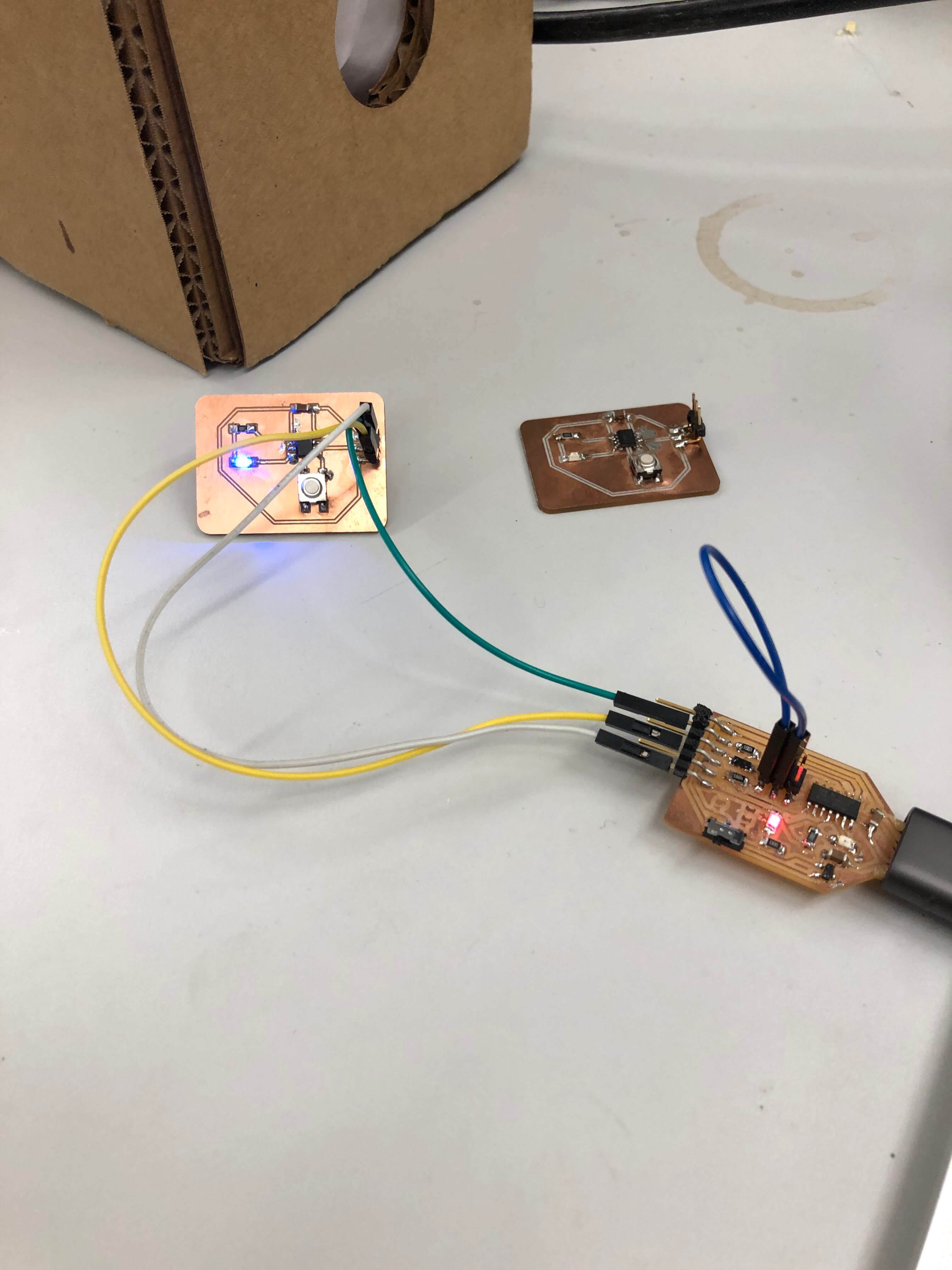
The reason I switched the pin to pin 2 is because the LED was wired to pin 2 on my ATTiny. I figured this out by looking at the pinouts. When I tested this code, it worked, resulting in this
To test that I was indeed controlling the board I changed the value of the delay to 500 milliseconds, resulting in this working example.
Arduino Programmer with Pushbutton Code
Once I had turned my Arduino into a programmer, it was relatively easy to program the pushbutton example as well. I simply used the same code as my SAMD programmer, just configured the board as Attiny, and the programmer as jtag2updi. It worked and this is the result.
This is the code that I used.
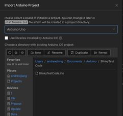
Platform IO with Arduino Uno Internal Blink
This week, I also tried to program something in Platform IO, another IDE that you can use inside Visual Studio. To install it I went to Visual Studio, then went searched up extensions and searched Platform IO. Then I installed it.
Then I went to the icon that popped up on the bottom of my taskbar that looked like this.

Then this is the sidebar of PlatformIO

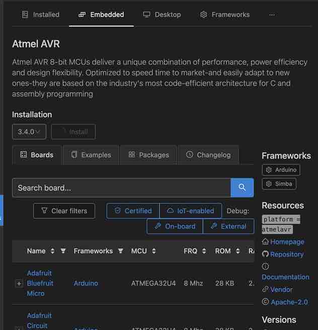
Next I downloaded the Atmel AVR library in Platform IO, which let me use an Arduino Uno.
Finally, for the code, I imported the Arduino internal blink code example. As a reminder, that’s this code.
// the setup function runs once when you press reset or power the board
void setup() {
  // initialize digital pin LED_BUILTIN as an output.
  Serial.begin(9600);
  pinMode(13, OUTPUT);
}

// the loop function runs over and over again forever
void loop() {
  digitalWrite(13, HIGH);   // turn the LED on (HIGH is the voltage level)
  delay(500);                       // wait for a second
  digitalWrite(13, LOW);    // turn the LED off by making the voltage LOW
  delay(500);                       // wait for a second
}
It looked like this
Once I had the code, I uploaded it onto the Arduino, and this is what resulted.
Unfortunately, I was not able to get really any farther past this with PlatformIO.
Week 05 Group Work
Comparing the SAMD11C architecture
Testing
For this week, I worked on testing the architecture of the SAMD11C microchips that all of our lab’s students used in their programmers. More information about the programmers can be found on our instructor Dr. Harris’s site, or in our week 5: electronics production documentation. Since I had previously lost his programmer, I had to make another one, and so it was the perfect opportunity for him to test the SAMD11C’s architecture.
After remilling and soldering the components on once again, my programmer looked like this
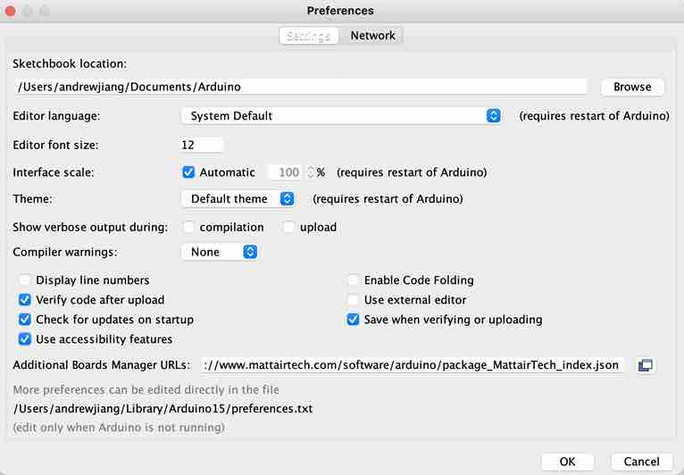
I then plugged it into his computer to verify that it got power, and the middle red led lit up, indicating that it did accept power. After turning it into a programmer once again with an ICE board, I then pulled up Dr. Harris’s site once again and went through some of the steps for testing code. First I had to download the mattairtech additional boards url so I could configure the settings for the SAMD chip in Arduino. I went to the Arduino software, and went to File->Preferences and copied this link into the Additional Boards Manager box.
https://www.mattairtech.com/software/arduino/package_MattairTech_index.json
This was the result
First, I wanted to test that basic serial communication could be established between the board and the computer, so I wrote some basic print code as shown below
void setup() {
  Serial.begin(9600);
}

void loop() {
  Serial.print("hello");
}
This was the result
After testing that it could establish serial communication, which it could, I tested its capabilities by blinking the internal LED. This is the code I wrote, and its really just the modified blink code. I checked the pinout of the SAMD and the LED was connected to pin 2.
int led = 2;
// the setup routine runs once when you press reset: void setup() { // initialize the digital pin as an output. pinMode(led, OUTPUT);
}
void loop() { digitalWrite(led, HIGH); // turn the LED on (HIGH is the voltage level) delay(1000); // wait for a second digitalWrite(led, LOW); // turn the LED off by making the voltage LOW delay(1000); // wait for a second }
This is what happened when it worked.
To make sure that it controlled the LED, I made it blink faster, changing the delay to 500 ms instead of 1000 ms. I found success.
Conclusion
With each test of the SAMD11C, the uploading time was a lot slower compared to other chips since the software always had to go through the extra steps of writing bytes to flash. However, the SAMD11C is one of the most versatile microchips, and you either turn it into a programmer for other microcontrollers, or just program the SAM chip directly. Thus I think that the SAM architecture is a strong contender within all the different kinds of microcontrollers because it is a lot more flexible than say, an ATtiny412.
Go to our group site to learn more about our group work
Week 05 Files
Click here to access my files for this week