Week 16. Interface and Application Programming (May 3)
Week 16 Assignment
- write an application that interfaces a user with an input &/or output device that you made
Joystick Tracker
This week the idea for application programming is an joystick tracker, or a program that will read in the joystick analog values, and map them onto a graph so that you can visually tell where the joystick is being moved. The assignment is met since it interfaces with the joystick (input device).
I decided to use Processing for the visual aspect since it is very compatible with Arduino and reading serial values. The assignment for this week most likely won’t be included with the final project, so I didn’t really feel that I had to use many different softwares above and beyond for this week.
Learning about Processing
To learn about processing, I did a tutorial on how to code in processing recorded last year during the pandemic by Mr Dubick. Since I do have a background in java, this was a good refresher on how to do visual programming, since the programming done within this course has mainly been about hardware/embedded programming.
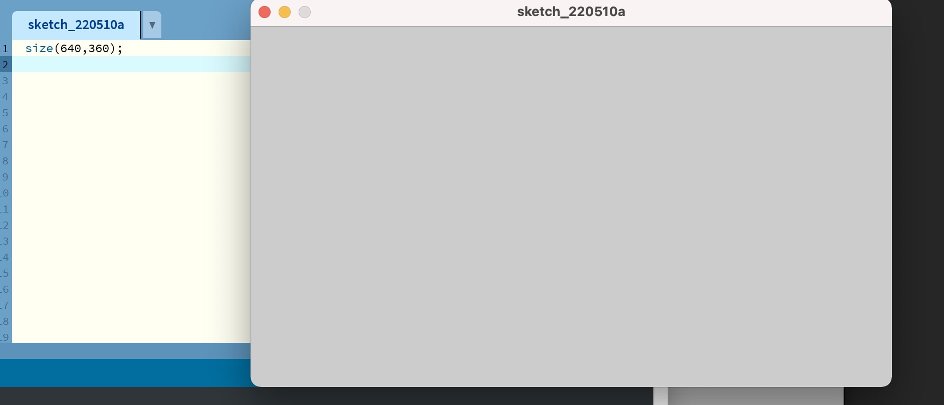
Following the tutorial, I started by creating a background of size 640 width and 480 height
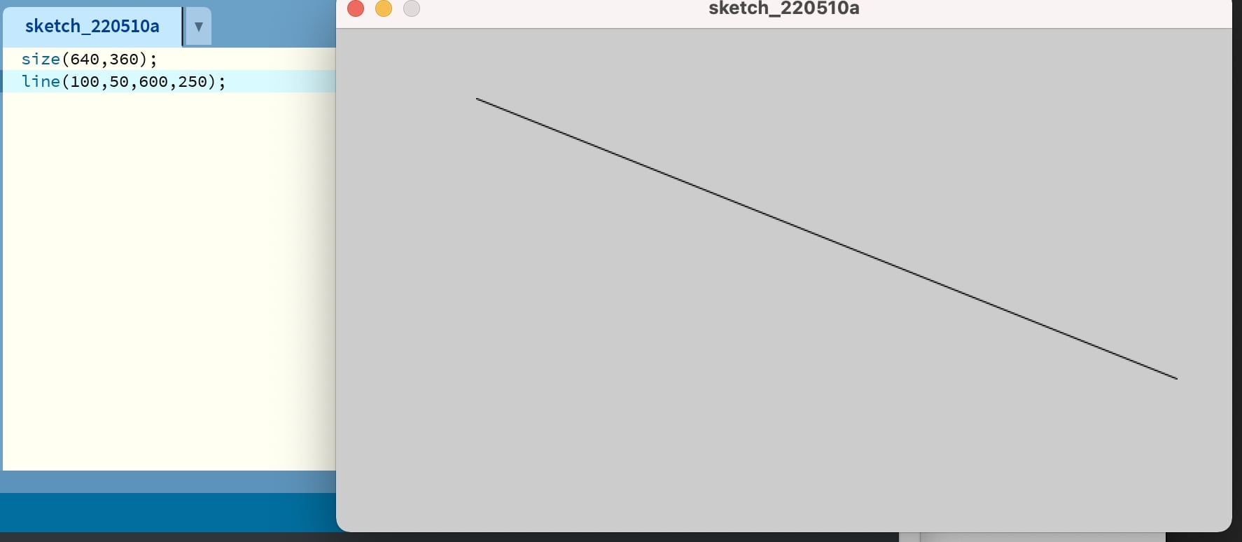
Next I created a line. This takes 4 parameters for the x0, y0, xf, yf.
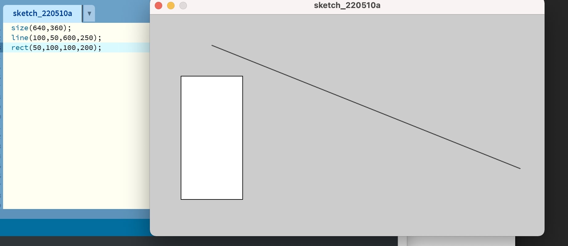
Then I drew a box. This took four parameters too which are identical to the line
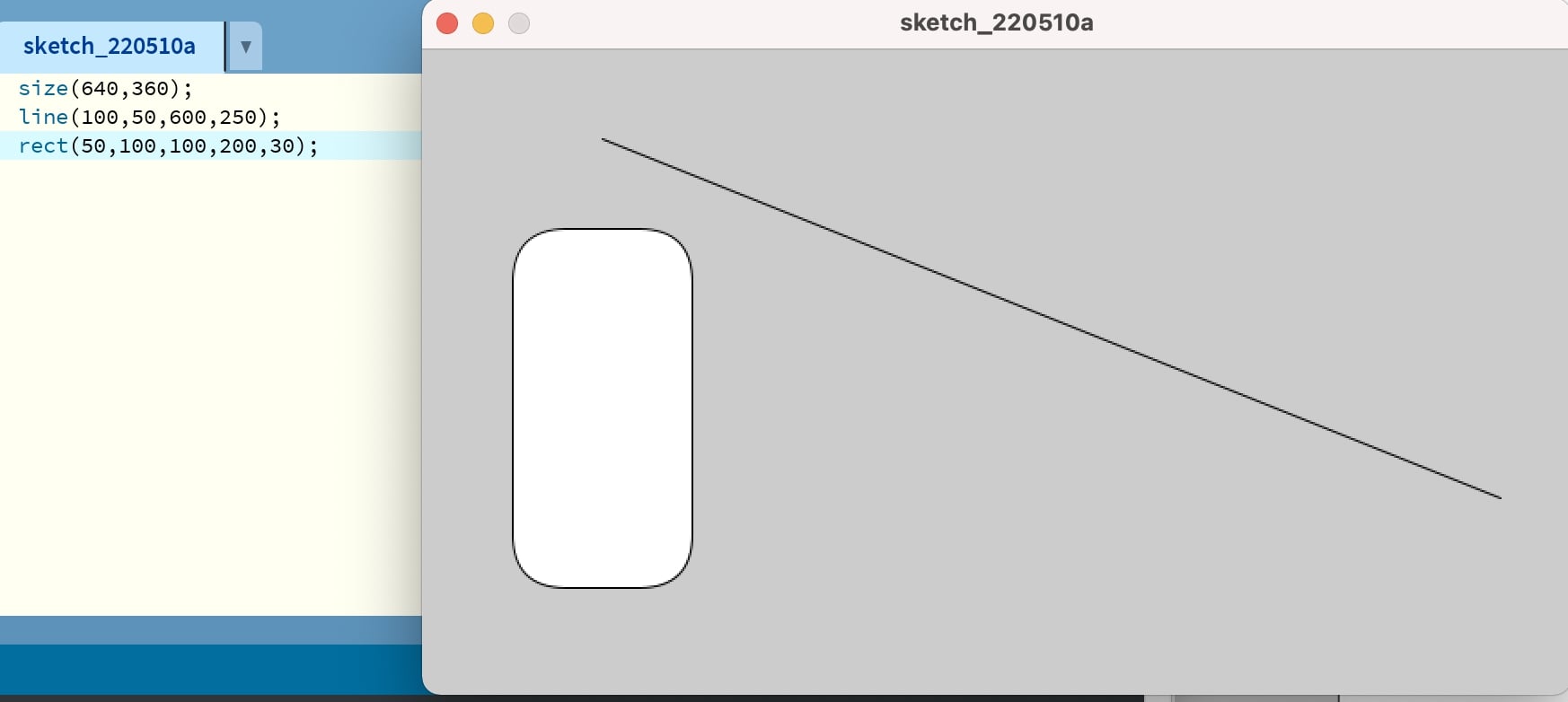
Next I created a curved box by adding an argument parameter, making it 5 parameters
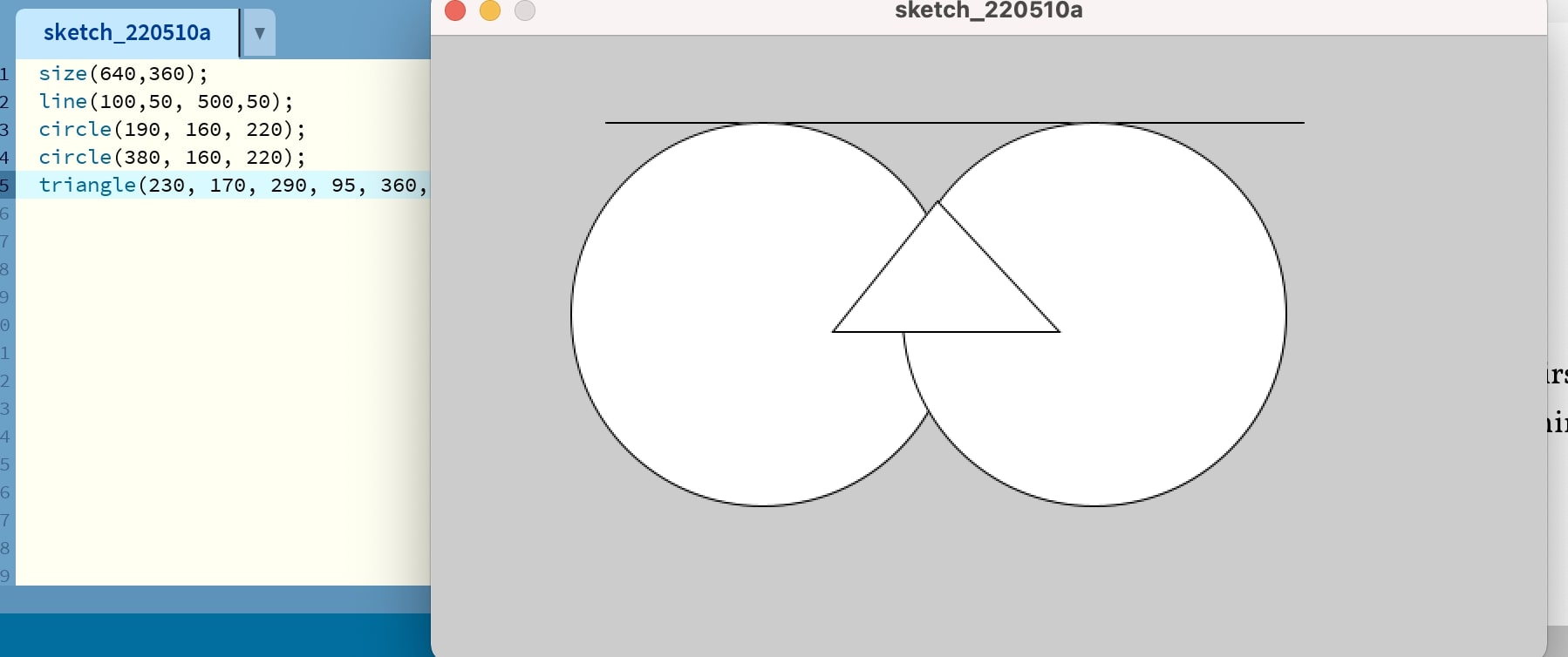
Then I created this face using a line, triangle, and two circles. Triangles take 6 parameters for x,y positions for each vertex, and circles take 3 parameters for center x,y location and radius. These are all 2D primitive commands.
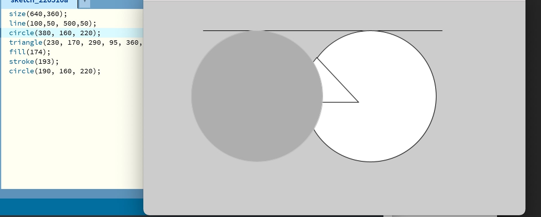
Finally, I changed the color of one of the circles from pure white to gray. Here I used only one parameter for the fill command, which automatically means a grayscale color system, but it’s possible to do RGB with the same command with 3 parameters instead.
All of these examples were simply designed to refresh me on visual programming and not actually completely reflective of the assignment for the week. I still found it super beneficial to do. While doing the tutorials, I looked at the Processing reference guide to remind myself how to draw all these shapes, which was very helpful
Reading Basic Serial in Processing
For this week, unlike other weeks, I had a clear idea of what I wanted to do. My thought process was that since I had to catch up on previous weeks, and that this likely wouldn’t be used in the final project, that I would not go that above and beyond for this week’s assignment. The first crucial step I identified in getting a joystick tracker to work was first getting a simple serial output to be viewed in processing. I find that this decomposition mindset–breaking larger problems into smaller more manageable steps–to be very beneficial throughout this program.
I started by looking at some past websites online to get an idea of how to use processing with serial, specifically by looking at Dr. Taylor’s archived fab site to get a sense of how the serial in processing is used.
First I tested that the joystick code I wrote prior actually worked in Arduino IDE, since if this code itself didn’t work then there was no way the processing code would work. I found success.
As a reminder, that previous code for the joystick I wrote is this.
int VRx = A0;
int VRy = A1;

int xPosition = 0;
int yPosition = 0;
int mapX = 0;
int mapY = 0;

void setup() {
  Serial.begin(9600);

  pinMode(VRx, INPUT);
  pinMode(VRy, INPUT);

}

void loop() {
  xPosition = analogRead(VRx);
  yPosition = analogRead(VRy);
  mapX = map(xPosition, 0, 1023, -512, 512);
  mapY = map(yPosition, 0, 1023, -512, 512);

  Serial.print("X: ");
  Serial.print(mapX);
  Serial.print(" | Y: ");
  Serial.println(mapY);

  delay(100);

}
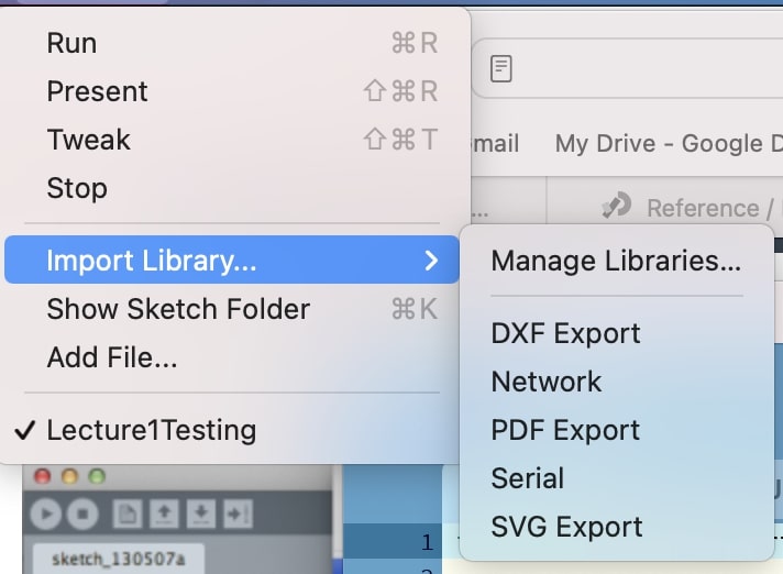
Then I learned from further research into the processing reference guide regarding the serial library that I needed to import the serial library: processing.serial, into processing IDE in order to print and read serial. My plan was to upload the Arduino sketch which would print serial values, and then read those values in processing and do what I needed to do with them.
First I tried a basic serial print “hello” sketch. Most of the code for that sketch came from this sparkfun tutorial, with modifications specific to my system of course. Initially, I kept getting this error when trying to use the COM port of the arduino telling me it was busy.
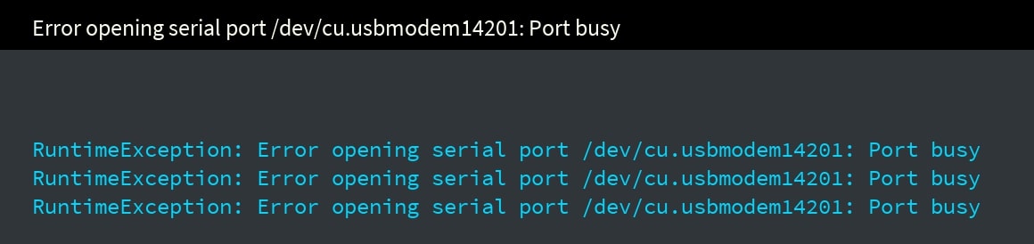
Then I realized that I had to close the Arduino window since it was using the port already, and two programs can’t use the same port at once. Once closing the Arduino window and reuploading I found success.
This was the hello world code. I have added comments here unpacking each section of the code to make sure I understand completely how it works.
import processing.serial.*; // imports serial library

Serial myPort;  // Create new serial port
String val;     // Creates holder for data received from the serial port
void setup()
{
  String portName = Serial.list()[4]; // this is the Arduino usb port for
                                      // my mac
  myPort = new Serial(this, portName, 9600); // assigns myPort object to
                                             // Arduino port
}
void draw()
{
  if (myPort.available() > 0)
  {  // If data is available,
  val = myPort.readStringUntil('\n');         // read it and store it in val
  }
println(val); //print it out in the console
}
Joystick Code V1
The next step in the decomposition was for me to write some code to read in the joystick values being printed by the joystick. The thought process I had when doing this was just to take the existing print hello code and modify it a little bit to read the joystick analog values
This was the joystick code. I again put comments there unpacking each section of the code.
import processing.serial.*; // imports the serial library to processing

Serial myPort; // defines Serial port object myPort
Integer XPos;
Integer YPos; // defines two ints which will storre the x and y values of the joystick
String x;
String y; // defines two temporary variables representing the serial read

void setup() {
  String port = Serial.list()[4]; // assigns name of port to 5th COM port, we know that the 5th port is the arduino
  myPort = new Serial(this, port, 9600); // sets myPort to a new serial port
}
void draw() {
  if (myPort.available() > 0){ // checks if the serial port is available
      x = myPort.readStringUntil('\n');
      y = myPort.readStringUntil('\n');
  }
  delay(1000);
  println(x + " " + y);
}
After first uploading the sketch in Arduino IDE, closing the window, then running the sketch in processing, I found success.
Once this step to read in the joystick values worked, I tried working on the visual aspect of my joystick graph. First, I created a background for the visual, and I made it bright blue at first as a test of the RGB values.
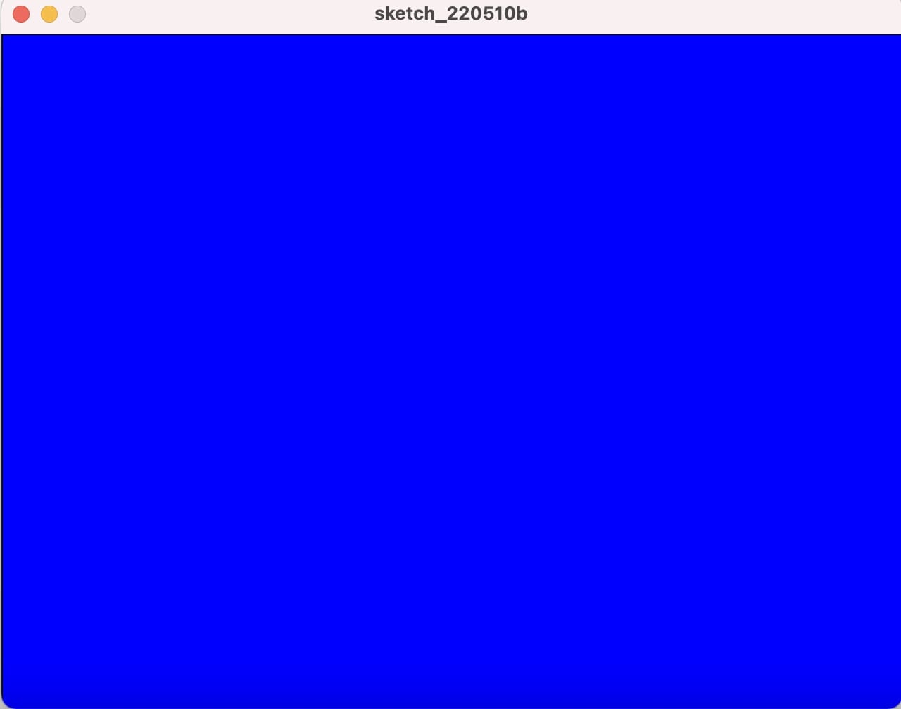
Here is the code I added to my previous serial joystick read code. It’s put into the void setup because we only want the background to be there once.
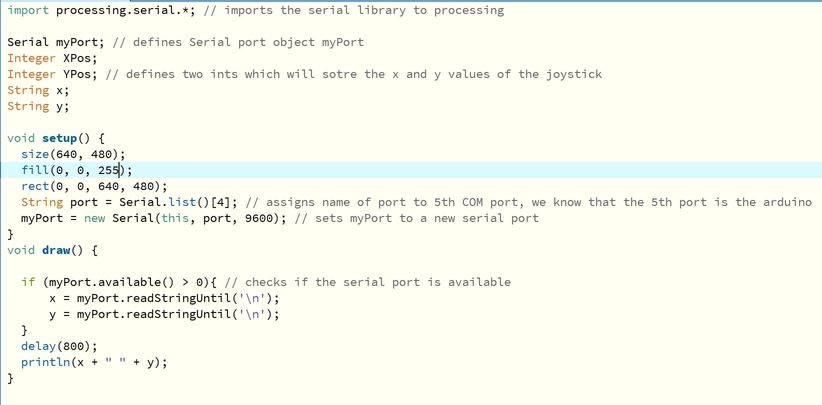
With this success, I added even more onto the visuals. I added X and Y axis label text to be able to tell which direction was which. I also changed the background color to yellow so one could see much clearer.
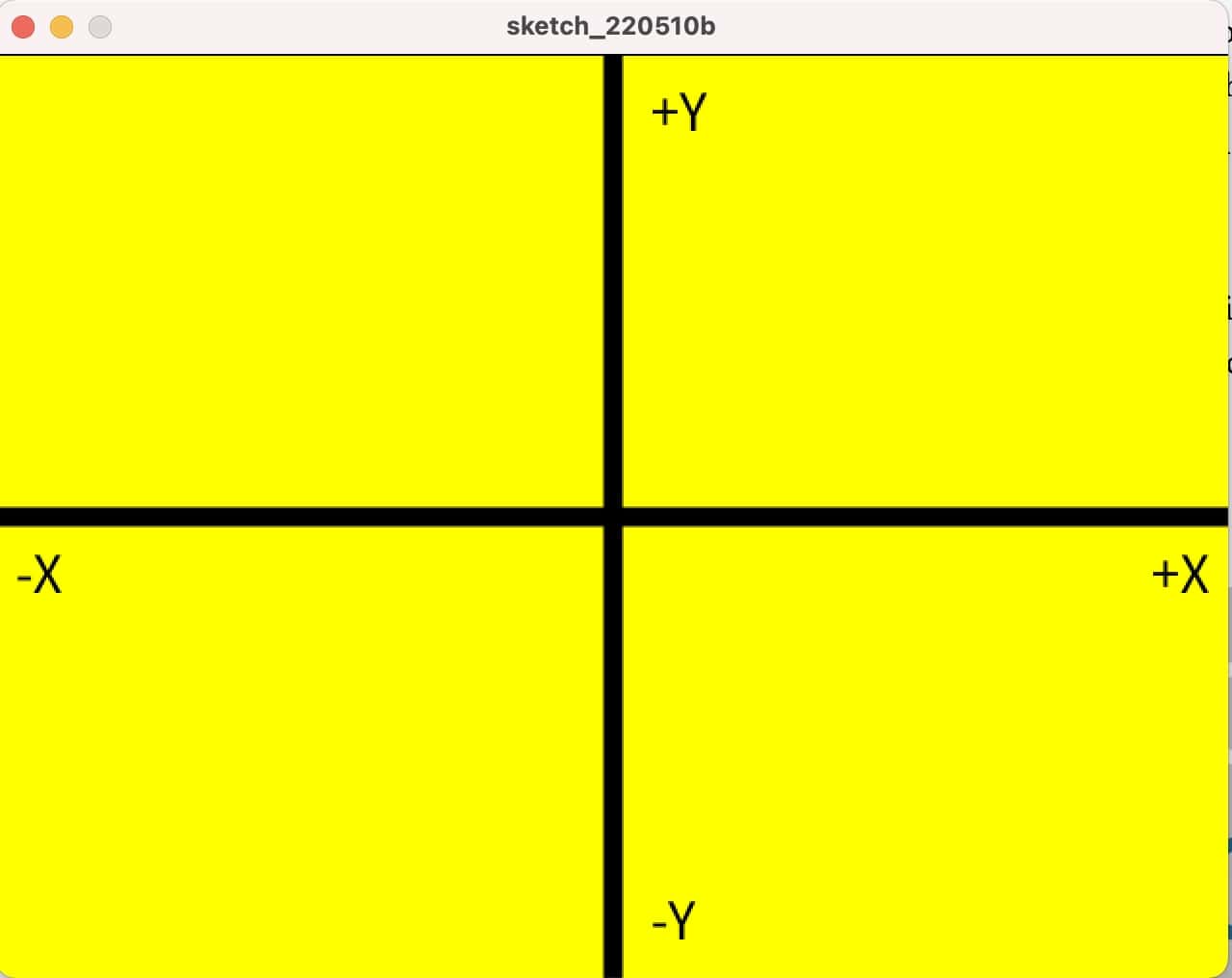
Here is the code I made to do that, which is again in void setup since this code is only supposed to run once.
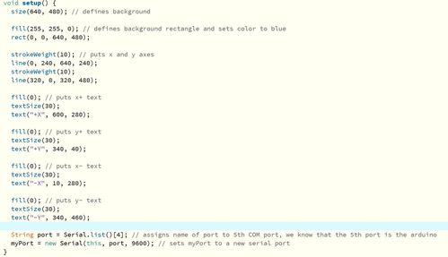
The next step, which was to print out the serial text values of the joystick, onto the background, repeatedly gave me problems. The problem was that the serial monitor was repeatedly printing out null values in addition to the joystick position values, and so when I tried printing out the joystick values to the screen, I would get NullPointerExceptions for trying to print out a null value. To try and solve this I tried many different solutions. The first thing I tried to add was a line
while (x != null && y != null){}
I thought this line would help the code ignore the time when the x and y values were null, but after runnning it, I got the same exact error. Another thing I tried was adding a delay, since it seemed like what was happening was that the Serial output null values were too quick for the code to ignore, but this did not have any effect whatsoever. After running out of ideas that I could think of at the moment, I decided to scrap this specific program and start over. More research was needed.
Joystick Code V2
It turns out there were some problems with how I wrote the last version of the joystick code which I found in my research. As mentioned prior, the previous joystick code for processing had been created by taking the basic Serial read code and modifying it to read joystick values and print those out on the console. However, that was my mistake, as now I wanted a different outcome from the program than printing to the console, so simply changing the basic serial program wasn’t going to be enough to get it to read a joystick and store those values on a graph.
After scrapping the previous idea, I decided to do some more research on specifically joysticks and processing, not necessarily serial and processing. I found this resource which was very helpful, and I basically borrowed their code with some changes to it based on my system.
Here was the original Arduino Code for the Joystick from the site
const int SW = 2;
const int VRx = 0;
const int VRy = 1;

int xAxis = 0 ;
int yAxis = 0 ;
int Switch = 0 ;

void setup()
{
  Serial.begin(9600) ;
  pinMode(SW,INPUT) ;
  digitalWrite(SW,HIGH);
}

void loop()
{
  xAxis = analogRead(VRx);
  yAxis = analogRead(VRy);
  Switch = digitalRead(SW);

  Serial.print(xAxis,DEC);
  Serial.print(",");
  Serial.print(yAxis,DEC);
  Serial.print(",");
  Serial.print(!Switch);

  Serial.print("\n");

  delay(10);
}
Here was the original V2 Joystick Processing Code
import processing.serial.*;
Serial port;

int x;
int y;
int Switch;
PFont f;
String portName;
String value;

void setup()
{
  size ( 512 , 512 ) ;

  port = new Serial(this, Serial.list()[0], 9600);
  port.bufferUntil('\n');
  f = createFont("Arial", 16, true);
  textFont ( f, 16 ) ;
}

void draw()
{
  fill(0) ;
  clear() ;
  fill(255) ;

  if (Switch == 1) // if the button is pressed
  {
    // draw a larger circle
    ellipse(x/2,y/2,100, 100);
  }
  else
  {
    // draw a smaller circle
    ellipse(x/2,y/2, 25, 25);
  }

  text("AnalogX="+(1023-x)+" AnalogY="+(1023-y),10,20);
}

void serialEvent( Serial port)
{
  // read the data until the newline n appears
  value = port.readStringUntil('\n');

  if (value != null)
  {
        value = trim(value);

    // break up the decimal and new line reading
    int[] values = int(splitTokens(value, ","));

    x = values[0];
    y = values[1] ;
    Switch = values[2];

  }
}
Some notable differences from this to the V1 code that I wrote entirely myself are
-
the use of the serialevent() function. This function, as explained on the Processing documentation, is only called when serial data is available, meaning it would ignore all of the null values in the serial monitor. I forgot to include this function into my V1 code, and that’s the main reason why it kept recognizing the null analog values and giving me the NullPointerException
-
creation of a new font. This step is completely optional since the font really doesn’t matter.
-
the bufferUntil() function, which allows the program to call the serialEvent
I had to make some modifications to their code to get it to fit my setup. Beceause I wasn’t using the built in switch of the joystick I had to take out all the code referencing a switch. Also, some of the Vrx and Vry pin numbers were changed to match. Next the plan was to first upload the Arduino code, then close the serial terminal, and then upload the processing code. I tested this first on an arduino, and then on the ATTiny1614 board that I made during input week.
Final Arduino Joystick Code
const int VRx = 7;
const int VRy = 6;

int xAxis = 0 ;
int yAxis = 0 ;


void setup()
{
  Serial.begin(9600) ;
}

void loop()
{
  xAxis = analogRead(VRx);
  yAxis = analogRead(VRy);

  Serial.print(xAxis,DEC);
  Serial.print(",");
  Serial.print(yAxis,DEC);

  Serial.print("\n");

  delay(10);
}
Final Processing Joystick Code (here I’ve once again included descriptive comments)
import processing.serial.*; //import the Serial library
Serial myPort; // define the port

int x; // variable holding the value from A0
int y; // variable holding the value from A1

PFont f; // define the font variable
String portName; // define the port Name
String val; // define the data being read in

void setup()
{
  size ( 512 , 512 ) ; // window size

  // we are opening the port
   myPort = new Serial(this, Serial.list()[4], 9600);
  myPort.bufferUntil('\n');

  // choose the font and size
  f = createFont("Arial", 16, true); // Arial, 16px, anti-aliasing
  textFont ( f, 16 ) ; // size 16px
}

// drawing loop
void draw()
{
  fill(0) ; // set the fill color to black
  clear() ; // clean the screen

  fill(255) ; // set the fill color to white

    // we draw a circle with a certain coordinates
    ellipse(x/2,y/2, 25, 25);


  // we display data
  text("AnalogX="+(512-x)+" AnalogY="+(512-y),10,20);
}


// data support from the serial port
void serialEvent(Serial myPort)
{
  // read the data until the newline n appears
  val = myPort.readStringUntil('\n');

  // when this value isn't null
  if (val != null)
  {
        val = trim(val);

    // break up the decimal and new line reading
    int[] vals = int(splitTokens(val, ","));

    // we assign to variables
    x = vals[0];
    y = vals[1] ;


  }
}
Here is me getting it to work on an Arduino
This is the final product where I got it working with an ATTiny1614
Overall, this was a fairly calm week after the great struggles which I faced last week. Since this likely won’t be a part of the final project, I didn’t feel as pressured on this assignment, but I’m still really proud of myself and how I was able to get it working so smoothly, something that I definitely would not have been able to do before Fab Academy.
Week 16 Group Work
Coming soon!
Week 16 Files
Click here to access the files for this week.