Week 4. Computer Controlled Cutting (Feb 8)
Week 04 Assignment
-
Cut something on the vinyl cutter
-
Design, lasercut, and document a parametric construction kit, accounting for the lasercutter kerf, which can be assembled in multiple ways,
-
For extra credit include elements that aren’t flat
Below you will find my documentation and notes regarding the fourth week of Fab Academy, which includes cutting out a custom sticker on the vinyl cutters and creating a parametric construction kit from the laser cutters.
Vinyl Cutting: Custom Android Studio Logo Sticker
This week, one of our assignments was to cut something out on the vinyl cutter. In the CAD design week, I had already chosen my design, imported it into Corel Draw, converted the pixels to curves, and saved it as a DXF file in Silhouette Studio, the software we use to control the Silhouette Cameo vinyl cutters. All I had to do this week was to actually seperate each layer by their respective color, cut each color of vinyl out seperately, and use seperate pieces of transfer tape in order to combine all the layers and paste the completed sticker on the window of our lab, which includes all the stickers from past Fab Academy classes as well.
This was the design I had picked last week, the Android Studio logo. I mainly picked out this design because it required slightly more advanced vinyl cutting and had a personal significance to me as an avid Java programmer

To start, I divided the design into four main parts: the black arms and legs, green head, white eyes, and blue body. However, I soon realized that I wasn’t really sure how I was going to seperate the design into its layers. I thought about copy and pasting my design four times, and then only focusing on one part with each design, but ended up using a method referred to me by fellow student Aaron Logan. This was to just cut one color at a time, and then Ctrl - Z to bring up a new color layer and repeat the process with all four layers.
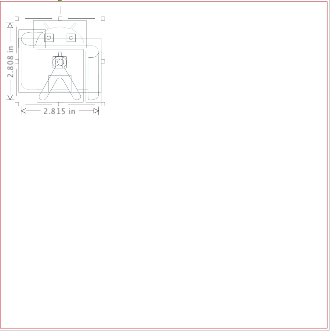
This meant that I would have to cut four seperate layers of their corresponding colors. I walked over to the vinyl shelf, and chose the four colors of vinyl I needed, and used scissors to cut out a manageable portion of each sheet. Then I went into the Silhouette software and imported the design I had created. Because all the student stickers had to fit onto the wall, one of my instructors, Mr. Dubick, required that the stickers be a maximum size of 3 x 3 inches. Thus, I resized the design down in Silhouette Studio, which resulted in this.
I was finally ready to start vinyl cutting. I decided to start with the green head first, since that was the most complete section and the easiest component to do. In Silhouette Studio, I simply deleted the other components of the design until only the head remained.

I then grabbed the blue cutting mat, and pressed the green vinyl down onto it so it sticked. I then went to the vinyl cutter, fit the cutting mat in between the blue marks, and pressed load cut mat, which rolled the mat into the machine.
However, the first time I tried to cut my design, I didn’t realize that the vinyl was not secured properly to the cutting mat. Thus this resulted.
As you can see, the vinyl slid around and didn’t exactly cut like I wanted it to. When I saw this, I immediately paused the cut operation, unloaded the cutting mat, and took off the vinyl from the mat. Then I rotated it to a side that hadn’t been cut, and pressed the vinyl down extra hard onto the mat. I retried the cut, and it worked perfectly.
To peel off the actual part I wanted, I took a pair of tweezers and peeled off the excess vinyl that I no longer needed. Then, I cut out a portion of the transfer tape, took off the cover, and stuck it onto the remaining vinyl. Carefully using the tweezers for assistance, I peeled up the tape, which peeled up the green vinyl, thus sticking the top side of the vinyl onto the tape.
I repeated this process with the three other components: the body, arms and legs, and eyes. This is what the three other components looked like in SIlhouette Studio


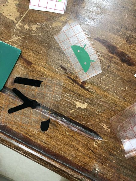
This is what the head and arms/legs looked like individually after they had been cut out.
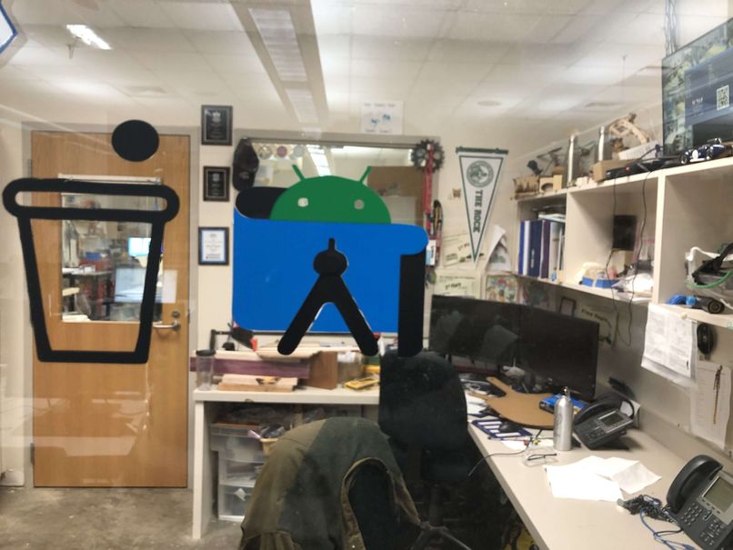
The final step was to assemble all the parts. Carefully, I took each component and placed them one by one onto the window, and then taking the tape off. This is what the final product looked like.
Lessons Learned - I learned how to do a layered vinyl sticker with different colors - I learned to always make sure the vinyl is completely secured to the cutting mat before vinyl cutting
Laser Cutting: Parametric Construction Kit
This week, we also had to design and create a custom parametric construction kit that could be assembled in multiple ways. At first when I heard these terms, I had no clue what they meant, but when my instructor, Mr Dubick gave the example of legos, it immediately clicked in my head. Then I realized that parametric design was simply, designing with parameters to replace values instead of using the values themselves. This would save a lot of time in many scenarios. For example if I wanted to change the sizing of a design, I wouldn’t have to change each individual dimension, but just change one parameter value and everything else would change according to that. In many ways, it was like a variable in programming, where if you changed that one variable value, it would change all the other instances of that value.
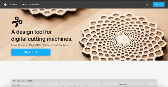
Although I now understood the concept, I needed to figure out which software I was going to use. Mr Dubick introduced us to Cuttle, a new CAD software that was really convenient with parametric design, but I chose to still use Fusion 360 as I had more experience with using it. Plus, I had never explored the parameter option in Fusion 360, so this would be a good way to further my Fusion knowledge.
I was referred to this Prusa Printers blog tutorial ) on parametric modelling in Fusion 360 by Mr Dubick, and I read through the website. Additionally, I watched the video that was linked until about the 2:20 mark, when I felt that I had sufficiently learned how to activate parametric design in Fusion 360, and was ready to actually try it.
This is the video I watched
The next step was to decide what exactly I wanted the pieces of my parametric construction kit to look like. To get some inspiration, I looked at the prior documentations of previous Fab Academy students, namely Teddy Warner and Jack Hollingsworth, to get some ideas. I ended up deciding on making a bunch of parametric tabbed shapes that I could assemble in multiple ways to make different things. For the actual shapes, I chose to use circles and triangles because I felt that these were interesting shapes to fit together, and I hadn’t seen someone do a circle before so I thought that I would give it a try.
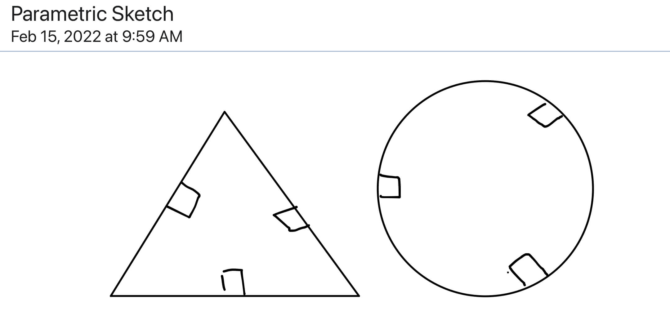
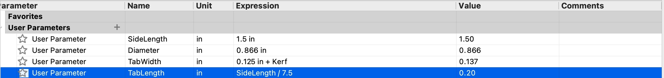
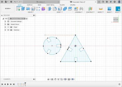
I opened up a new Fusion file, and created a sketch on the top plane. Then I drew a circle and a triangle. To use parametric design, I finished the sketch, went under the modify menu, and clicked change parameter. It brought up this parameter menu, and I created four seperate parameters for the side length of the triangle, diameter of the circle, width and height of the tabs.
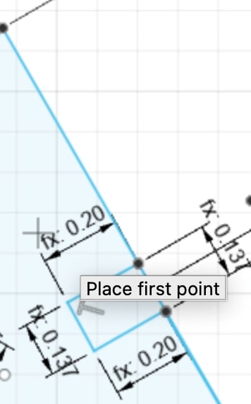
Then I went back into the sketch, and drew some sketch points at the midpoint of the sides of the triangle. I used the parameters by drawing lines to signify a rectangular tab, and then inputting the dimensions of the rectangle as TabWidth and TabLength for the horizontal and vertical dimensions. The tab looked like this.
I drew two lines down the middle axes of the triangle, with the intention of mirroring the tab over the line. When I mirrored it though, I realized that the parameters did not translate over the mirrored line. Thus, I had to manually trace the other two tabs with parametric dimensions instead of mirroring it. Finally, my triangular tabs were done, and I deleted the original side lines to reveal the tabs. It looked like this.
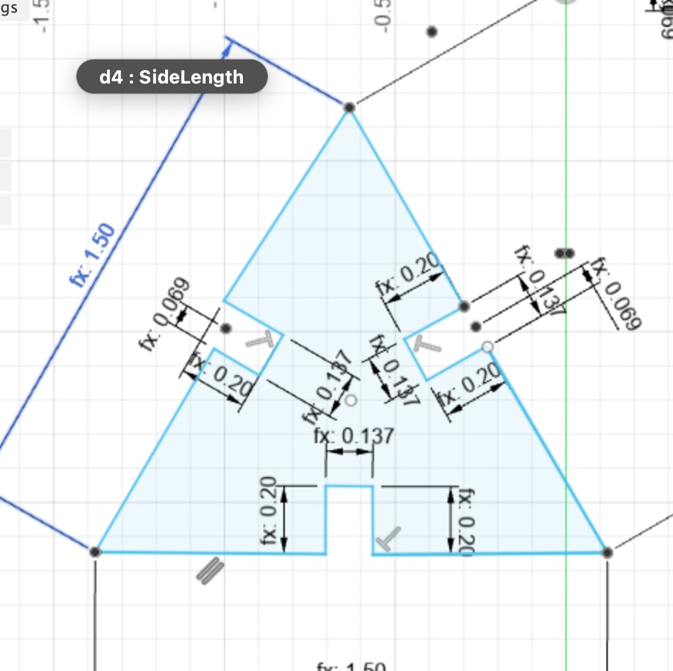
I realized the side lengths were a little bit too long, so I went back to the parameter menu and changed the tab lengths from 0.2 to 0.15. Then I repeated the process I had used on the circle. The almost finished design looked like this.
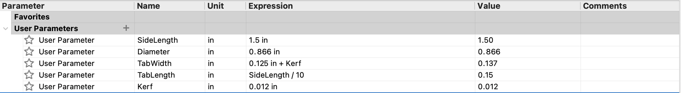
The final step in the design was to account for the lasercutter’s kerf in the design. In the group project this week, we characterized our laser cutter’s speed, power, rate, frequency, joint clearance, and kerf. Kerf is basically a measure of the laser cutters error when cutting. When you laser cut something, the laser doesn’t perfectly cut out the shape you want based on the design, and so you have to account for this error in your design. To do this I went back to parameters, created another one called kerf, and inputted the value we had measured for kerf, or 0.012 inches. Then I changed the TabWidth to 0.125 + kerf to account for it. Finally the design was done. This is what the finished parameters looked like.
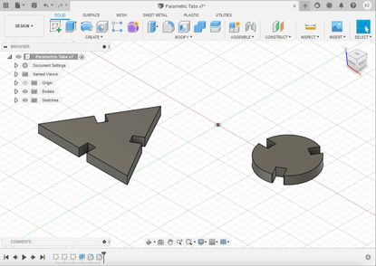
And this is what the finished design looked like after I extruded it.
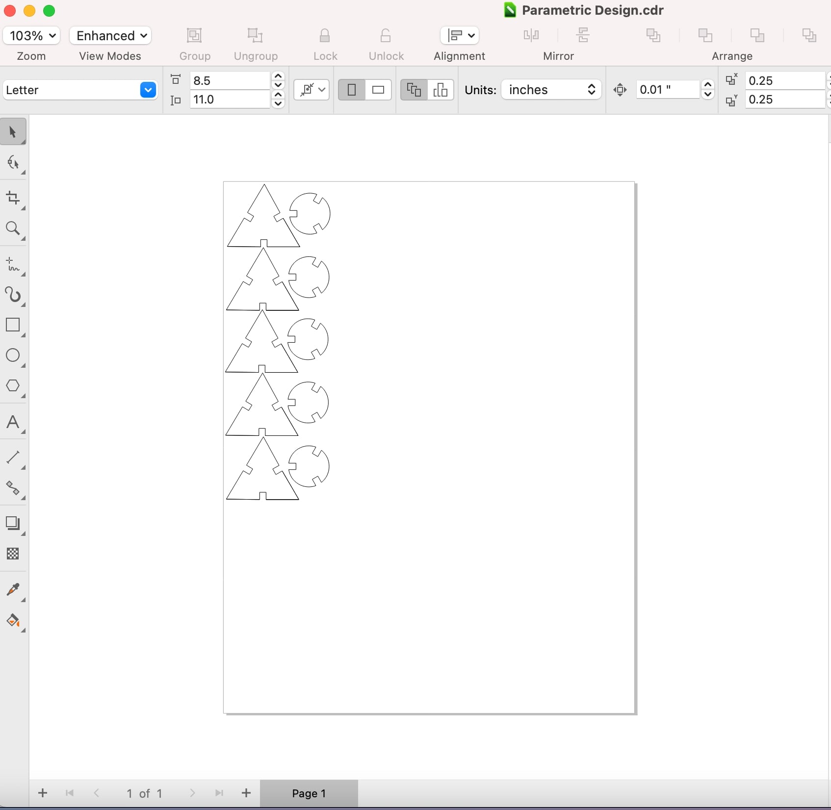
After the design, then came the actual laser cutting of the design. I exported the Fusion 360 file as a DXF, and imported it into Corel Draw. Then, I duplicated the design five times, since I wanted five of each piece. The design in Corel looked like this.
When I went to go cut out the pieces, I took the Corel Draw file, hit print, and imported in the material cut settings for cardboard. The laser cut looked like this.
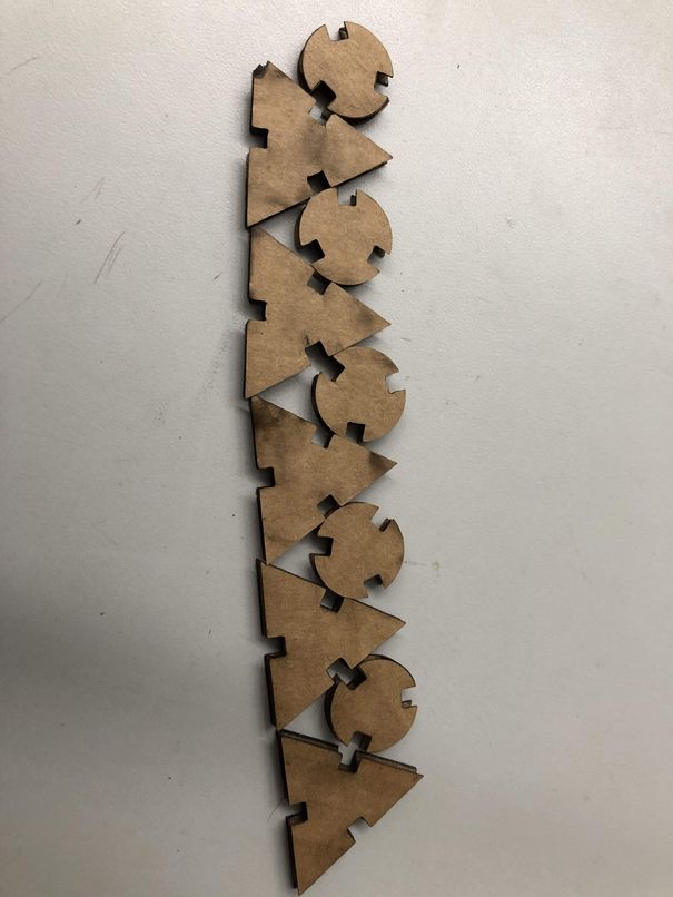
These were all the pieces I cut out
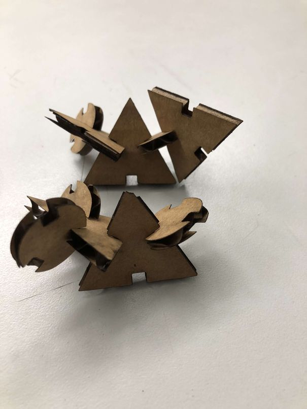
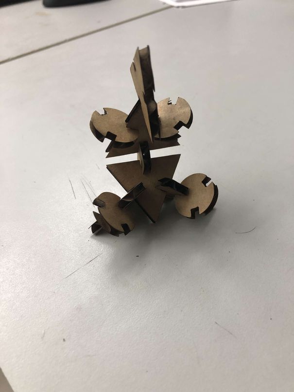
I then arranged my pieces into two seperate configurations to demonstrate that my parametric kit worked
Group Project
This week, we had our first group assignment to characterize the laser cutter. We had to characterize power, focus, rate, frequency, kerf, and joint clearance. After we divided up the work, I worked with my partner, Alaric Pan, to characterize the speed, power, and frequency of the Epilog Engraver.
To start, Alaric thought of the idea to use color mapping to have all the cuts of different settings on a single file. They then collectively decided to do all possible configurations of the 3 settings in increments of 25%. However, when they went to design it, Alaric realized that that would take 64 different lines, which they decided would be unreasonable, so they changed to increments of 33%. Andrew then came up with the idea to raster the speed, power, and frequency settings of each line next to the line to know which line had what settings after the cut. He also came up with the idea to have the speed, power, and frequency values of each line correspond to the line’s rgb values for color mapping. This would make inputting the settings when sending the cut much easier as they would just have to line up the cut settings with the rgb values.
The following images are the results of the cut front and back:
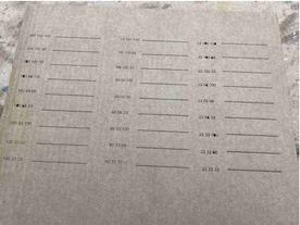
As you can see the lines with the settings in the order (speed, power, frequency), (100, 33, 100), (100, 33, 66), and (100, 33, 33), did not cut through. The optimal cut settings would maximize speed while minimizing power and frequency to make the cut fast while conserving energy and have less strain on the laser cutter. Alaric and Andrew determined that for most cuts the optimal settings would be (100, 66, 33) in the order of (speed, power, frequency). Cuts that need extremely high quality/precision, however, can use (100, 66, 100) since there are slight imperfections in the cuts with 33 or 66 frequency.
More information can be found on our group site
Week 04 Files
Click here to access my files for this week.