3. Computer-Controlled Cutting
This week I worked with parametric design in Fusion 360 by creating a cardboard press-fit construction kit on a laser cutter, made a two-color sticker for our lab’s office window on a vinyl cutter, and worked with our lab’s group of students to create our group website and characterize the focus, power, speed, rate, kerf, and joint clearance of our lab’s Fusion Pro 48 laser cutter. (Feb 10)
13-17 minutes
Parametric Laser Cutting
Parametric Testing in Fusion 360
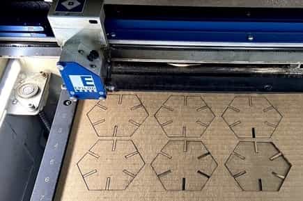
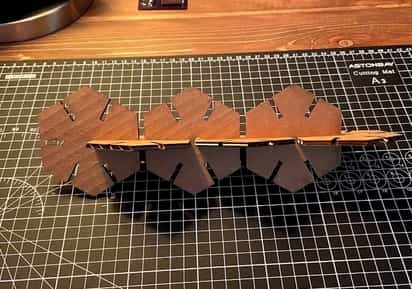
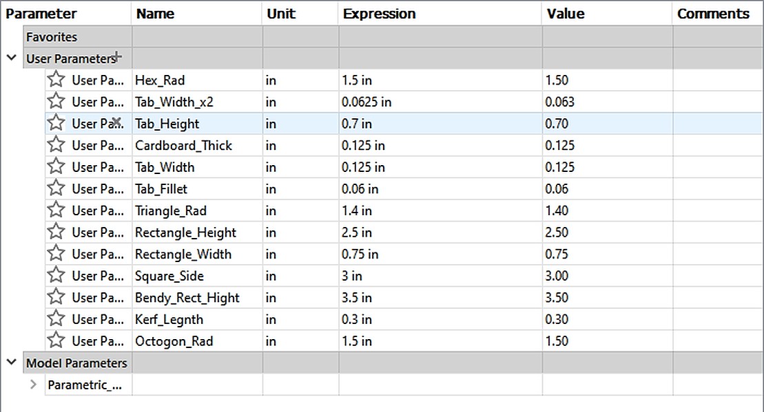
The first personal task for this week was to design and laser-cut a press-fit construction kit making use of parametric design, a new practice for me. Before even starting work on my press-fit construction kit I decided to take some time and experiment with parametric design in Fusion 360, and I created a simple press-fit hexagon, and cut it out of cardboard on a laser cutter. I introduced myself to this parametric design practice with some good tutorials, one from Prusa Research, and another by Makers Muse. Both of these gave me a better overview of parametric design, specifically in Fusion 360, and some of its design practices. The practice of assigning variables to measurements in my design was pretty straight forward, and as I became more comfortable with the process, it went faster and faster. However, after finishing the hexagon and attempting to change the parameters to enlarge the shape, I ran into issues with the shape deforming to fit the new measurements. I undid my changes to the parameters and added some more constraints to the sketch, and when I changed the size again, the hexagon held its shape. This test was relatively simple with there being a parameter for the hexagon radius, the tab height, the full with of the tab as well as 1/2 of the width for alignment to the sides of the hexagon. Although this design was simplistic, it offered a good introduction to the process of parametric design in Fusion 360. Below is an image of 6 of these test hexagon cut out of cardboard, and another of the 6 of them assembled in a line.
Press-Fit Construction Kit
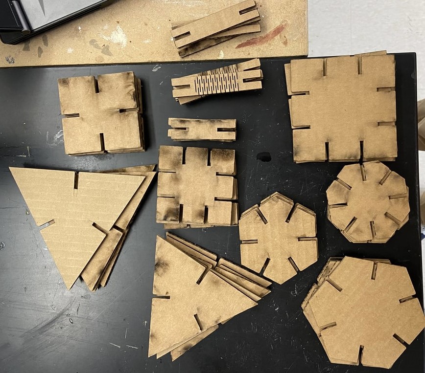
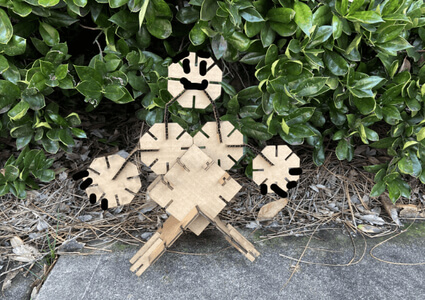
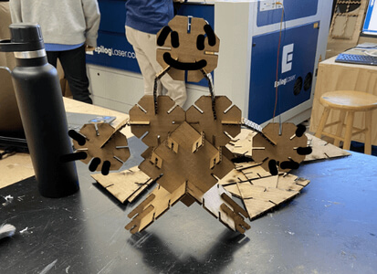
After starting this assignment by experimenting with parametric design in Fusion 360, I was ready to start work on my press-fit construction kit. I was inspired to make an array of different geometric shapes for my kit after remembering Magnatiles, a magnetic building kit that I used to play with all the time as a kid. The Magnatiles products are simple at heart, just a bunch of different colored shapes that attach magnetically. Despite this simplicity, messing with the toy for a little while you’ll find that you can use these simple shapes to make more complex structures & things. While planning my parametric press-fit construction kit, I kept this simple to complex path in mind and decided to cut an array of different geometric shapes consisting of hexagons, octagons, squares, rectangles, triangles, and a special rectangle with a bendy middle. All of these shapes attach with slots cut out on the sides. Each of these slots is filleted at the entrance to allow for corrections in slight misalignment when assembling the pieces.
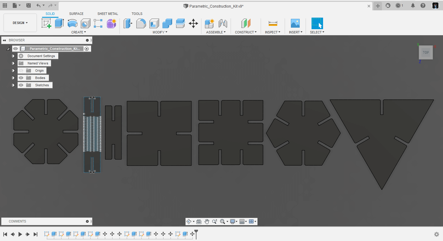
One perk of designing all of these shapes using parametric design features in Fusion is the ease of scaling. As shown in the video below, all it takes to resize one of these shapes is a change in parameters. Not only is this function helpful for resizing objects, but it is also especially applicable when doing something like the tab joints in my construction kit, as if the pieces don’t work a press-fit right off the bat, all it takes is a remeasurement of the join, and you can enter it in the parameter table and alter your design. To show some of the benefits of parametric design in my final press-fit construction kit, I used parameters to rescale some of the pieces, but not the joining tabs, so there will be a collection of different sizes of each shape, that all fit together.
Laser Cutting
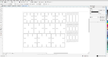
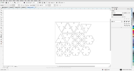
After completing all of the design work for my construction kit in Fusion 360, I exported each sketch of each different shape as a .dxf, before altering the parameters of some shapes and then exporting these larger shapes as .dxf files as well. Each of these .dxf files can be found by clicking on the link under the downloads section of this page. I found that while exporting these .dxf files, Fusion will save any construction lines used in your sketch as a solid line that will be cut by the laser. To work around this, I trimmed off any construction lines in my sketches after using them to position parts. This was a bit of a hassle to do, and also wasn’t the most convenient when using constraints, but after trimming these construction lines, the .dxf files generated by Fusion had no other flaws. I used CorelDRAW to import all of these separate .dxf files into a single document. It was here where I also duplicated these shapes into the wanted numbers and aligned them on the document to limit as much waste material a possible.
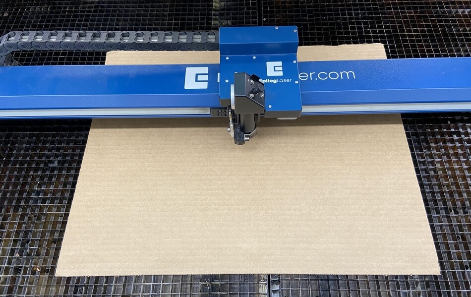
Once finishing the cut layout in CorelDRAW, I moved on to cutting the file on one of our labs Epilog laser cutters. Cardboard was my material of choice for this construction kit, as the infill of the cardboard is inherently springy, giving the press-fit function of this kit some extra strength. I used the print function inside CorelDRAW along with the Epilog Job Manager to set print settings and send the cut to the machine. During this process, I followed a workflow for our laser that I wrote over the summer along with Kai Vincent, a former student at my school and Fab Academy graduate. This file walks through the printing process on the machines and is attached below on this page.
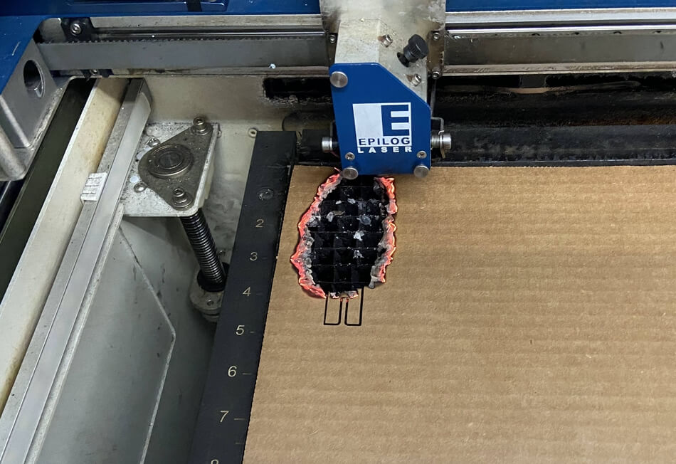
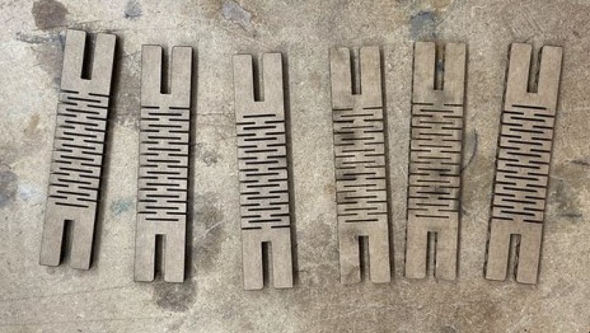
Having access to our Fab Lab during engineering classes has exposed me to the workflows of our lab’s laser cutters, and I feel comfortable with the cutting processes on the machines. This prior knowledge of the tool mixed with the cut settings we found in this week’s group assignment made for some pain-free cuts on the laser, with the only real problem occurring when cutting my kerf bending piece. The trouble I had with this cut came from my attempts to find the balance between the kerf lines being close enough to flex the material, but far apart enough to keep the cut from lighting aflame during the cut. After 2 attempts that resulted in flames, I finally got a working cut and cut out a couple more of these pieces for my final kit.
One final bit that helped me out through the week was a laser workflow for our labs Epilog Fusion Pro 48 that I wrote with another student of our lab & Fab Academy graduate Kai Vincent. This file, although written by me in the first place, helped me knock some rust off of the best safety practices for work with lasers (really helpful when experimenting with the kerf bending piece due to the risk of flames), and was nice to have not only when working on my construction kit, but also helped out while our group worked on this weeks group assignment, characterizing a laser cutter.
Final Construction Kit
Vinyl Cutting
Sticker Design
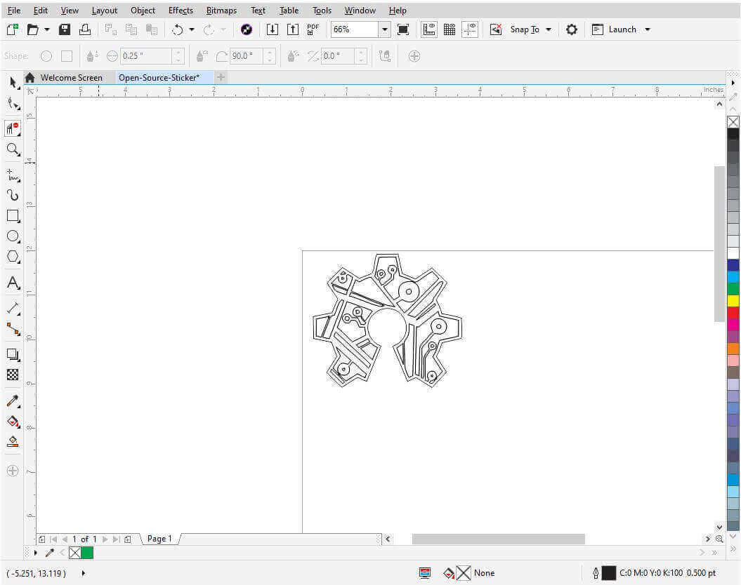
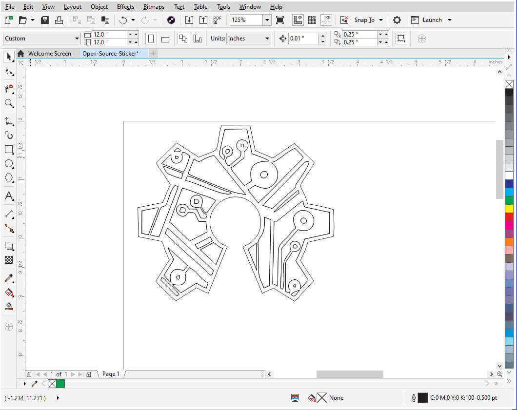
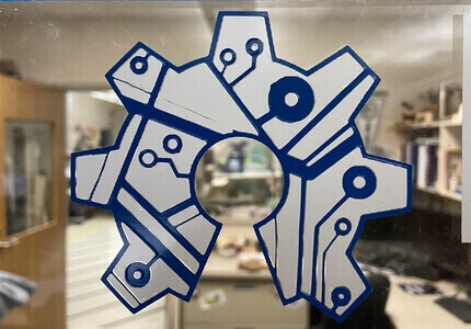
The second half of this week’s assignment was to cut something with a vinyl cutter. Since 2019 our lab has had a tradition of each Fab Academy student making a sticker for our instructor’s office window during this computer controller cutting week, and this year was no different. I started by brainstorming what I wanted my sticker to be and came out with two ideas, a street fighter style fight between two of our lab’s instructors, Tom Dubick and Dr. David Taylor, or the open-source hardware logo. Although I thought the street fighter sticker would have been amazing, we only had around 5” by 5” inches to work with for all of our stickers to fit in a row on the window, so I opted for a cool open-source hardware sticker traced from a tattoo design from dribble.com. After saving this image to my laptop, I used CorelDRAW to trace and alter the bitmap image into a useable SVG.
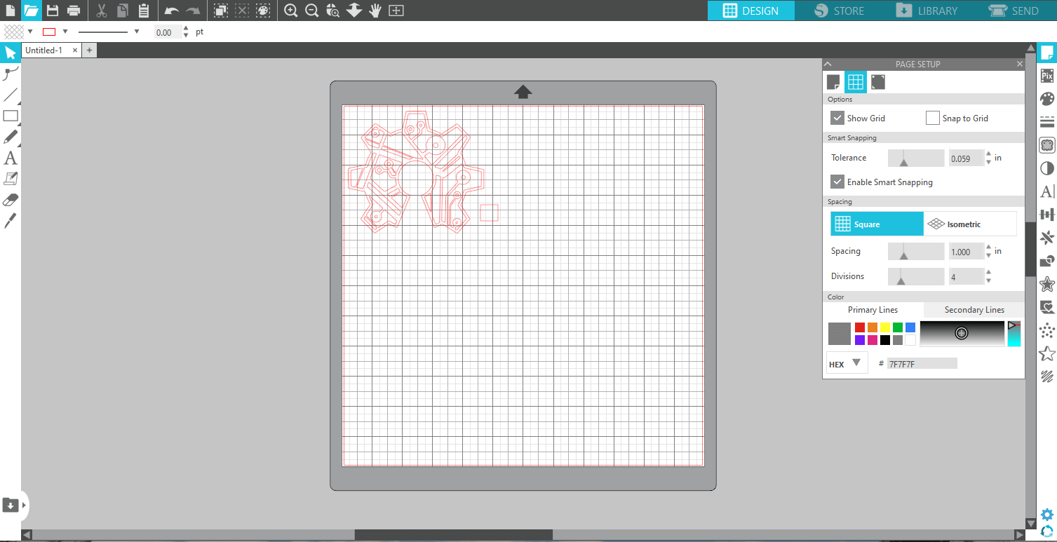
Silhouette Studio Work
After altering this image and saving it as an SVG, I opened it up in Silhouette Studio, a software that converted my SVG to code readable by our labs vinyl cutters. Here I also added a little box in the bottom left corner to help with the alignment of the layers of my sticker during the post-processing process. I settled on making my design dual-color, a white logo with navy blue accents. Both of these layers were cut from the same design file shown below but weeded differently to make white the background, and the navy the outlines.
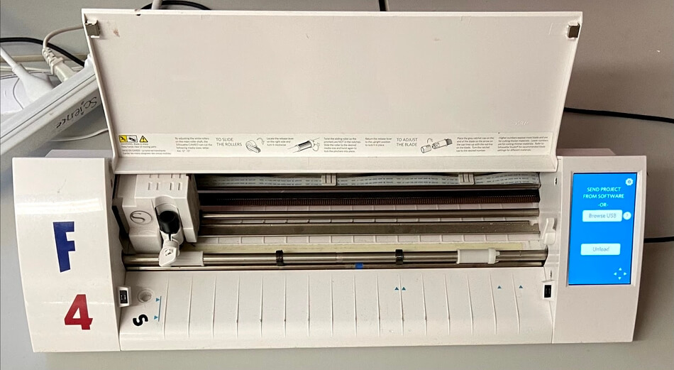
I then sent this file from Silhouette Studio to one of our vinyl cutters and cut the design on a square of glossy white vinyl. I repeated this cut, but on a piece of glossy navy vinyl instead and once this cut was done, I could move on to post-processing my sticker.
Post Processing
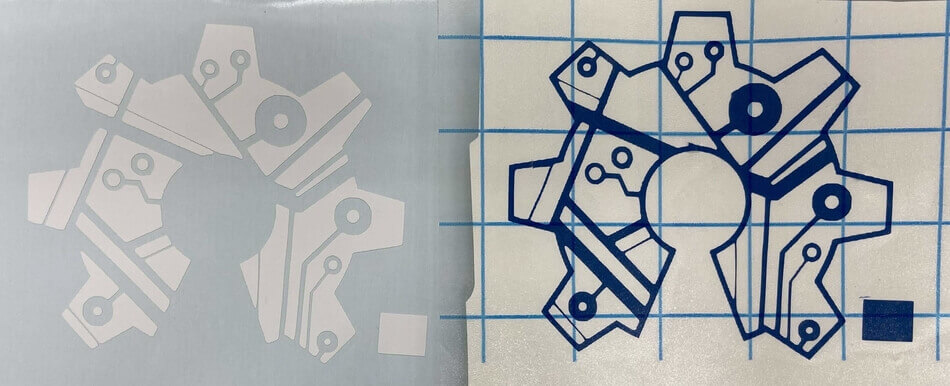
After both cuts finished on the vinyl cutter, I started the process of weeding the stickers, taking out the unwanted pieces of each color. For both the white and navy pieces, I removed the excess vinyl surrounding the sticker, and then for the white, I removed the outline pieces of the sticker, and on the navy I did the opposite, removing the centers of circles and the pieces between the lines of the design. I found that using a mixture of tweezers and an Exacto blade worked best for this process, however, I had one very thin line in my design that seemed to rip almost every time during this process. If I was really careful with the blade, I was able to separate this line from the piece next to it, however, the line never transferred well on the other sticker anyway, and thus my efforts to save it were fruitless.
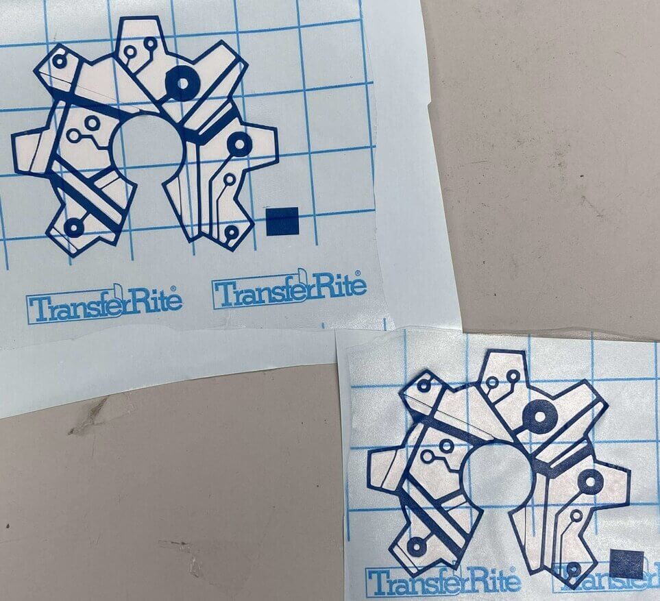
I transferred the navy part of the sticker to the white half using transfer tape, aligning them with the square I added in the design previously to be sure all of the features line up properly. This process was easier said than done, and I had to recreate the steps above 5 different times before I was finally able to align the two halves of the stickers in a way I was pretty happy with. None of these stickers turned out terribly, however, I wanted the alignment to be as close as possible before putting it up on the office window. None of these sticker attempts went to waste, as they looked cool enough for me to stick on a notebook and some folders I use for school.
Final Sticker
![]()
Group Work
In addition to this week’s personal assignments, we also had our first group assignment of the year. We were tasked with characterizing our Fusion Pro 40 laser cutter’s focus, power, speed, rate, kerf, and joint clearance. I documented this whole process on our Fab Academy group page with a little help from some of my classmates. Click here to view our group documentation site, with this week’s assignment on it.
Downloads
- Click Here to access and download all of my files from this week
Open Source Cookie Cutter
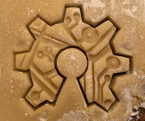
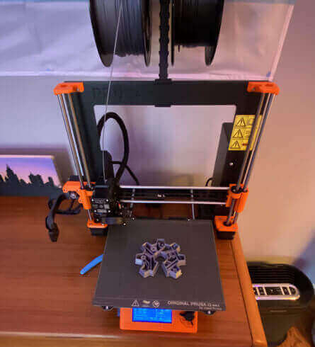
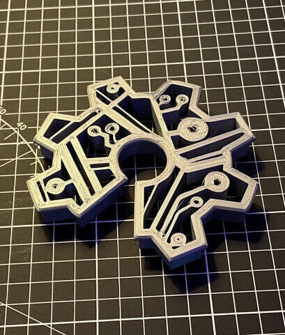
As a little side project for this week, I decided to work on my learned CAD skills from last week and combine an assignment from my bioengineering class in school with my Fab Academy work from this week. Our assignment was to design and 3d print a cookie cutter, so I decided to model my cookie cutter with the SVG I made in CorelDRAW on the open-source hardware logo. I imported my SVG design into Fusion 360 and extruded it into a body. Then I added an offset to the top rim, to give the cutter a larger top surface to press on and ran a fillet on this lip to make the rim smooth. I also cut away the embossing part of the cutter, as I only wanted the outline to cut all the way through. Finally, I added a chamfer to all the bottom cutting edges so the cutter could go through the dough easier.
I printed this model with a grey PLA on my Prusa I3 MK3S+. Unfortunately, I didn’t have access to food safe PLA, so the cutter was only one-time use, just for testing. The print quality was ok except for a rocky-looking first layer due to the nozzle starting too close to the bed, however, I caught this very early into the layer, and used the printers Live Z Adjust feature to raise the layer height.
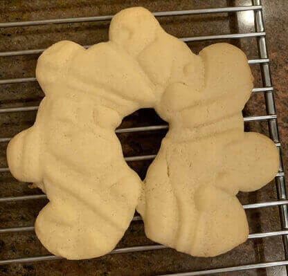
Conveniently enough the morning after I finished printing this cookie-cutter, my mom and brothers made some sugar cookies with my grandma’s recipe for Valentine’s day, giving me the perfect opportunity to test out my cookie cutter. While using the cutter I had to keep in mind the depth I set the emboss of the cutter back because, as shown in the video below, if the dough is too thick, it will pull the dough with the cutter, and if its too thin, the cookie will not be embossed. After a couple of attempts, I got a cookie-cutter and embossed it with the cutter, and was able to cook it when the rest of the cookies were cut out by my brothers. The final cooked cookie, the picture below, looks pretty wonky, but the test was relatively successful, and I’m happy with how the cutter came out.