12. Molding & Casting
In this week’s assignment, I experimented with 3-Axis Machining, rough and finish cutting a 3d fish mold, and casting parts with a mold made from it. (Apr 14) This week I attempted to challenge myself by using our labs ShopBot Desktop MAX, along with 3 to mill a 3D fish mold that I would be able to cast a soft mold from. I used this workflow as opposed to using a smaller Othermill Pro machine in our lab, as using this larger machine requires more tinkering with feeds and speeds, and forced me to become more comfortable with their concepts.(Apr 14)
16-20 minutes
Aspire File Work
Mold Modeling
Following along the same path I used in week 7’s computer-controlled machining class, I began this weeks mold making in Aspire. Although I’m much more comfortable using Fusion 360 for any CAD work, I was drawn to Aspire this week due to its 3D Clipart feature and decided to create the entire mold from CAD to CAM in Aspire. Aspire’s Clipart feature gives a user access to clipart libraries that can be imported and manipulated in an Aspire file, a feature I took advantage of to create the shape of my molds fish.
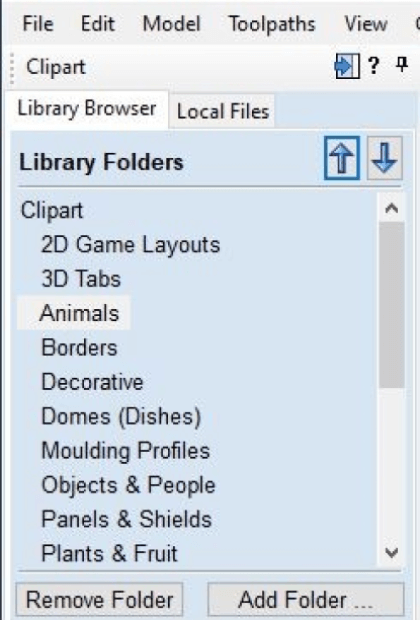
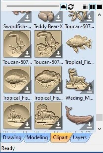
Before any of this could be done, however, I started by updating Aspire to V10.5, as its Clipart feature is most easily used in this version. This process took a bit of time, due to the lack of updates of Aspire on our lab computers. On the specific computer I was on, I had to update the software three separate times to get it to the most recent V10.5 version. With this done, I opened the newly updated Aspire application, and created a new file through the home pages Create New File option. In this new files workspace, I navigated to the bottom of the toolbar on the left side of the interface, and opened the softwares Clipart menu, by clicking on its corresponding tab. This menu opens a Clipart tab in your toolbar, displaying Aspires included clipart, organized into folders describing each, as shown in the image below. In my case, I navigated to the Animals folder under these included clipart libraries page and found a nice looking tropical fish clipart that I decided to make my mold from.
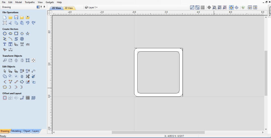
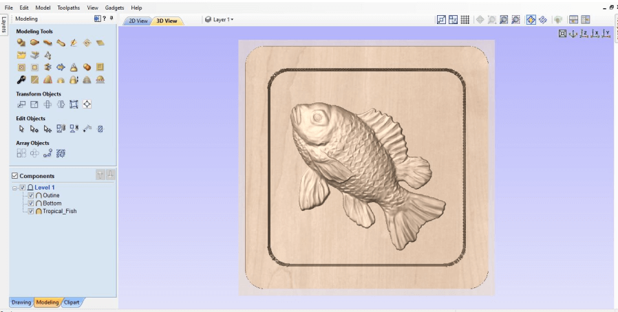
With clipart I liked picked out, I toggled back over to Aspire’s Drawing menu at the bottom of the toolbar on the left side of the screen, to create an outline of my mold, where I could later add in this clipart. I began by creating the outline of my entire mold, a 4x4” square, and then created another smaller square offset on the inside of this larger one. Here I also threw in a 0.3” filled on the inside and outside corners of this created outline, as these features would allow for optimal smooth machining.
I next toggled back over to Aspire’s Clipart menu, and imported this fish clipart, scaling and rotating the design so it would sit at a nice diagonal inside of my outline created prior.
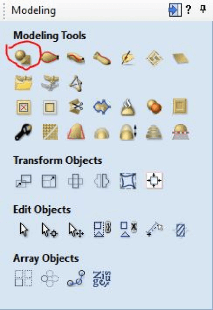
Switching to Aspire’s Modeling workspace (found in the same location as both the prior used Clipout and Drawing menus), I could next begin on converting my molds outline walls and base into a 3D shape around the fish clipart. Under Aspire’s Modeling menu, I used the first modeling tool (circled in red below), to extrude my mold outline and base vectors into 3d body.
I began by first selecting the inside square drawn earlier, representing the base of the mold, that this fish would sit on. I set this body to be 0.1” high, and left all other setting defaults, before clicking ok to create the base of the mold. I next moved onto creating the walls of the mold, using the same tool and default settings, but this time increating the height until the fish clipart could no longer be seen from a side profile, and then some. This confirms that my future milled mold will have a sufficient amount of silicon between the base of the mold, and the start of this fish, creating a more sound mold.
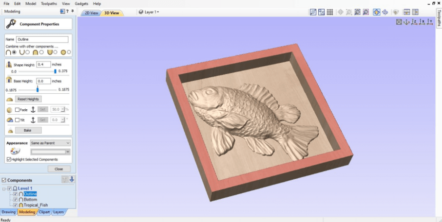
On my first run-through with this tool, I realized after viewing the model in Aspire’s 3D View that I had got to select the fillets while extruding the outline walls into a body, so I deleted the body and repeated the same steps take above to create a new one, this time including the fillets. I then toggled back into Aspire’s 3D view by going to the top of the workspaces model viewing window and selecting the 3D view tab. This time, after selecting the fillets, I was left with a more manageable shape for the machine, shown in the image below.
Toolpath Generation
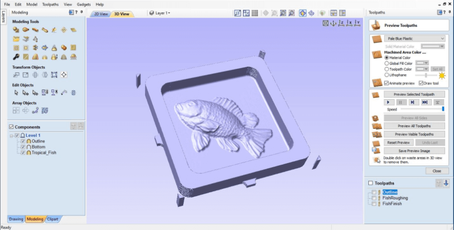
With the design work for my 3D fish mold complete, I next moved onto creating the toolpaths to mill the mold in Aspire. Due to the 3 Axis milling that would be used to create the 3d fish mold, this shape required three different toolpaths, one 3d roughing pass to remove most of the material around the fish, a 3d finishing pass, to mill out the detail work of this fish, and a profile cut around the entire mold, to cut out the mold.
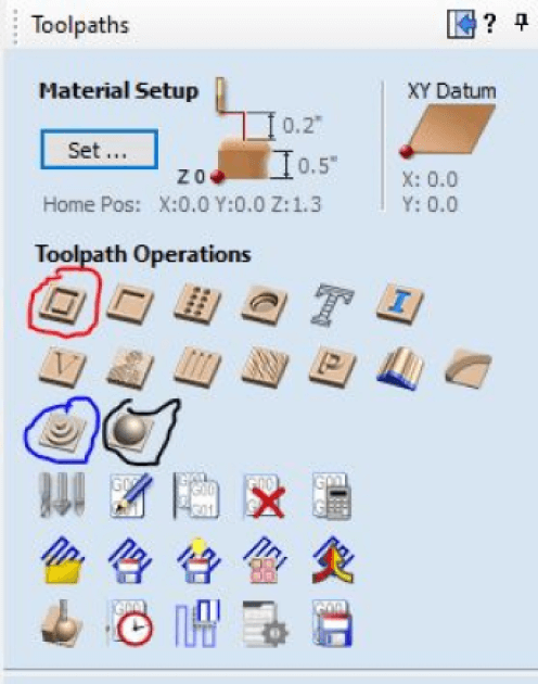
I began creating these toolpaths in the Toolpath menu found on the right sidebar of the Aspire interface. I made all three of these toolpaths in this menu, starting with the molds profile toolpath using the Profile toolpath tool circled in red above. Under this tool, I selected the outer profile rectangle of my mold and told the toolpath to cut it out, down 0.5”, the height of my used stock. Also under this menu, I turned on ramping plunge movements on the profile, as this ramp puts less stress on the endmill while cutting, as I explained in my week 7’s computer-controlled machining documentation. For this profile toolpath, I also added a tab on each of the four flat sides of my mold, to hold the mold to the mold to the rest of the stock after the profile was cut. One thing I didn’t worry about during this toolpath creation was the bit I would use, and its feeds and speeds, as I planned to update these values after a little more research into them. I next moved onto creating the toolpaths for my mold’s fish, starting with the roughing toolpath. This roughing toolpath tool is circled in blue in the image above, and upon selecting it, I selected my mold’s fish shape and generated the roughing toolpath. Finally, I completed the 3d milling with the Finishing tool, circled in black above. I followed the same steps I used while generating the roughing toolpath here, opening the Finishing tool and then selecting my 3d fish, and then calculating my 3d finishing pass toolpath.
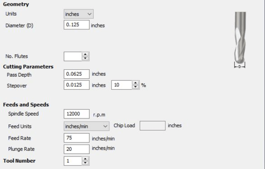
With these three toolpaths generated, I was next ready to flatten out the speeds and feeds, and bits used for each of these operations. I decided on milling my mold out of some 1/2” HDPE we had laying around in our lab, and cut this piece down to a 7x7” square, giving myself plenty of wiggle room to fit my molds 4x4” outline. Starting with my profile toolpath, I selected a 1/4” endmill in Aspire, leaving its default speeds and feeds, as these seemed appropriate for HDPE. Next, moving onto the molds roughing toolpath, I used a 1/8” straight endmill here, as this bit in comparison to something like a ball endmill dropped the cut time of this roughing pass significantly. After a bit of research and comparison to some working values found by my groupmate, Graham Smith, I found Aspires default settings are appropriate for the 3d roughing cuts flat endmill, except for an increased feed rate from 50 in/min to 75 in/min. Following that, I finished up my final toolpath, the 3d finishing operation, with the same bit settings as the flat endmill used prior, but by changing out the bit to a 1/8” ball endmill, allowing the operation to reach the smaller divets on the surface of the fish.
3-Axis Mold Milling
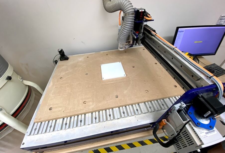
Upon completing my molds design work, I began the milling process on our labs ShopBot Desktop MAX. The CNC milling process I took while milling this part is talked about in-depth on my week 7 computer-controlled machining page, and this section of this page will simply cover what I did to manufacture this mold, and will not be an in-depth explanation of the process, as found on my week 7 page.
I started this mold milling process by preparing the machine and stock material, attaching my 1/2” HDPE stock piece to the bed of our CNC with four screws, one in each corner confirming flush mounting. Next, I homed both the machine’s X and Y axes to the bottom left corner of this stock page and zeroed both of the axes to match my mold design’s origin.
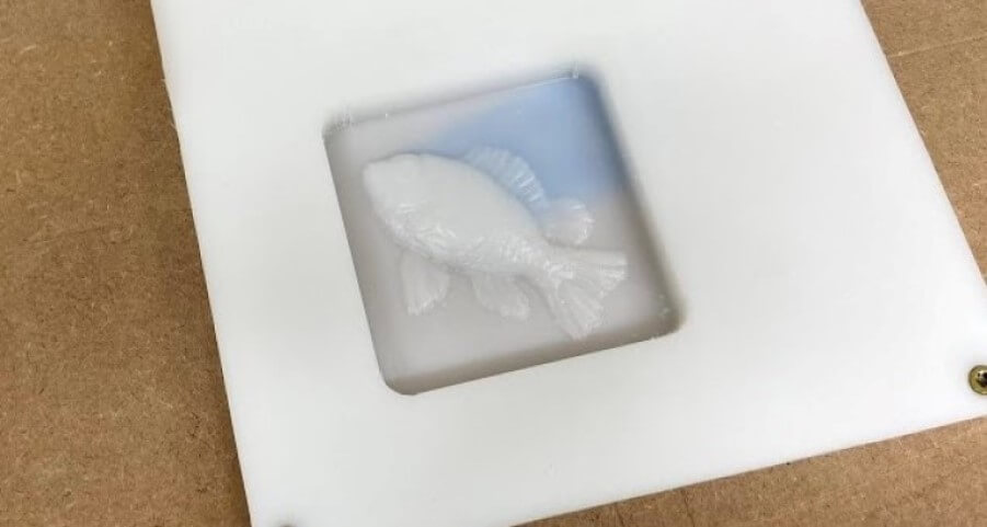
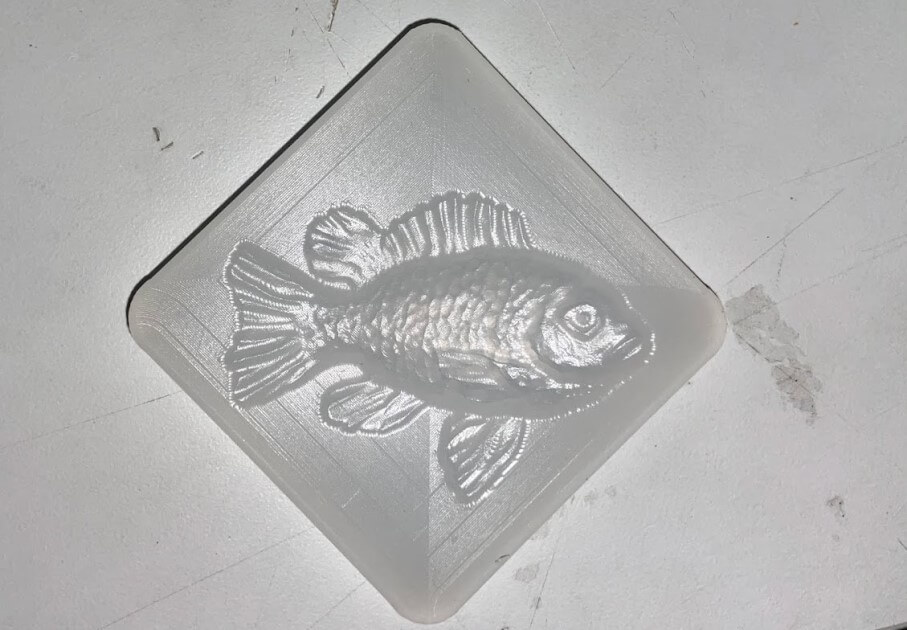
From here, I attached the first required bit to the CNC, a 1/8” flat endmill for my molds 3d roughing toolpath, homing the z-axis with the bit attached with our machine’s Z-axis probing plate, before running the generated 3d roughing toolpath for my mold. Next, I repeated these same steps for my molds 3d finishing toolpath, this time installing a 1/8” ball endmill, before reprobing the z-axis and starting the finishing operation. These two operations left me with a sweet-looking fish, shown below.
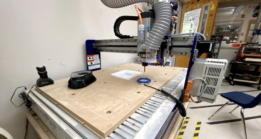
With the milling operations for the 3d fish part of my mold completed, I was ready to run the final profile toolpath generated, to cut out my milled mold. I started by installing a 1/4” flat endmill on the ShopBot Desktop MAX, and just like the two bits before it, probed the bit with our machines Z-axis probing plate, shown in the image below.
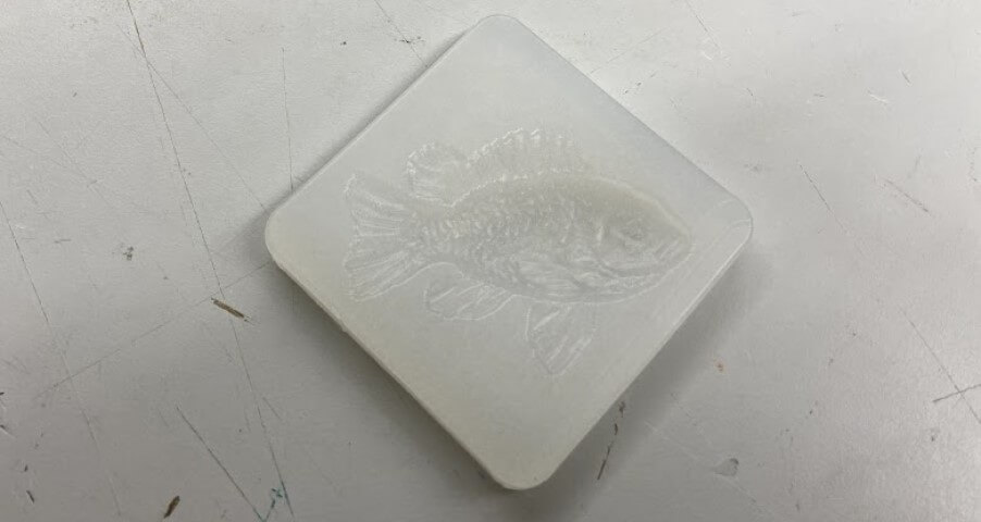
Once probed, I rehomed the machine to the bottom left corner of my stock and ran my mold outline profile operation, leaving me with a cutout and completed fish mold, shown below.
Casting
Moving onto the bulk of this week’s assignment, I began the process of molding and casting from my recently milled 3d fish mold. In this molding and casting process I split up into two different sections, first casting the molds, and next to casting the final parts. Because my goal was to have all hard casts as outputs, the mold that I would cast these pieces from would have to be soft, and therefore I began the molding and casting process by casting soft silicone molds from my milled part.
Casting Molds
I used two different types of silicon while casting these two molds, experimenting with the slightly different properties of each one. Although both silicons are from Smooth-On, the 20T and Dragon Skin silicons are slightly different, with the Dragon Skin yielding a softer, more flexible rubber, and the 20T a more grippy piece. After my work molding and use of these two molds, documented below, I found that although the material has a longer set time, I preferred the material qualities of Dragon Skin while casting hard plastic parts, as the mold seemed to release from the part easier, and also left a slightly higher detail on the fish.
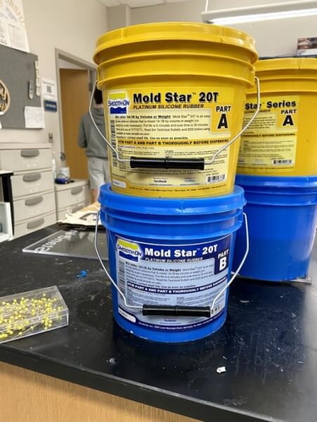
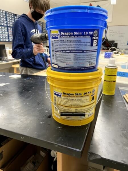
Both the 20T and Dragon Skin materials are two-part casting materials, where a part A and a part B are mixed in a 1:1 ratio, and then cast. I followed the same process while casting both of these silicone molds from my milled mold, first measuring out both parts of each silicon in cups, using a scale to ensure equal parts. I then moved on mixing both measure parts of the silicon in a singular cup and used a wooden dowel to combine the two parts, being as careful a possible to move the dowel back and forth, and not mix in any unnecessary air bubbles. Fortunately enough for me, both of these silicons could be cased without removing air bubbles in a vacuum or pressure chamber, saving me a step before moving onto poring.
The pouring of each of these casts went pretty smoothly, during which I started by setting up my milled mold on a sheet of cardboard, and then on both pouring occasions for each of the two silicons, poured the silicon mixture slowly into one corner of the mold, letting the silicon fill all of the milled molds small divets to retain as much detail as possible. After the pouring of each mold, I gave the mold a little shake and hit it against a table a couple of times to bring any air bubbles in the cast up to the surface, and finally, I was ready to let each of the molds set. The set time varied among the two silicons I used, with 20t taking half an hour to set, and the Dragon Skin taking 75 minutes.
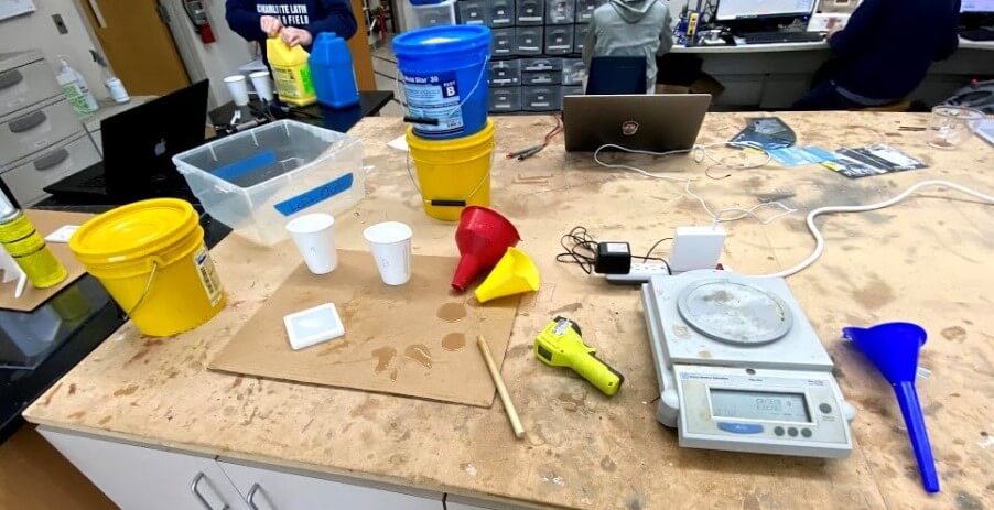
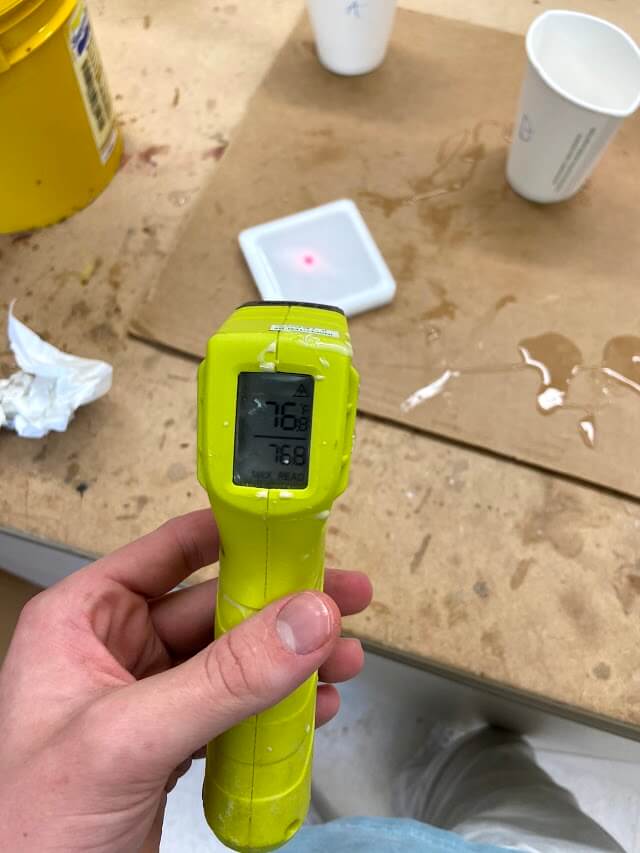
Throughout the setting process of both of these silicons, the cast remained around room temperature, as according to both silicones data sheets, that was the approximate temperature each of the materials would cast at. I measured this temperature with an IR thermometer gun, confirming its setting temperature around that give one the datasheet.
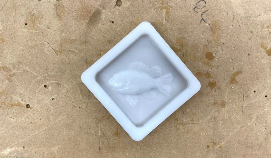
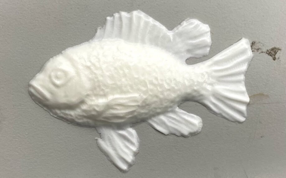
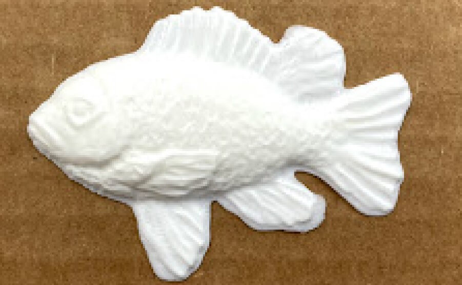
I followed this casting process from both the 20T and Dragon Skin silicone molds and was left with some pretty great-looking results, shown below.
Smooth-Cast 300 Casting
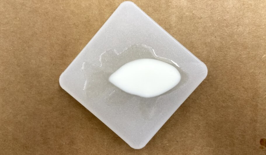
With both of my soft silicon molds completed, I could finally move onto casting hard parts, where I took advantage of Smooth-On‘s Smooth-Cast 300 material. Similar to both of the silicones I cast previously, this liquid plastic material is a two-part material, where both parts are mixed at a 1:1 ratio. I followed the same measuring, mixing, and casting steps take earlier to cast the silicone molds, except this time, I cast Smooth-Cast 300 into both of my soft silicone molds. This process, as shown in the timelapse below, is pretty cool, and very quick. The set time for the liquid plastic material is only around 5 minutes and turns visibly while hardening. The materials setting reaction is also exothermic, so along with the visual color change indication, the material heats up quite a bit while setting. Below are my casted results from both my 20t and Dragon Skin silicone molds
Chocolate Casting
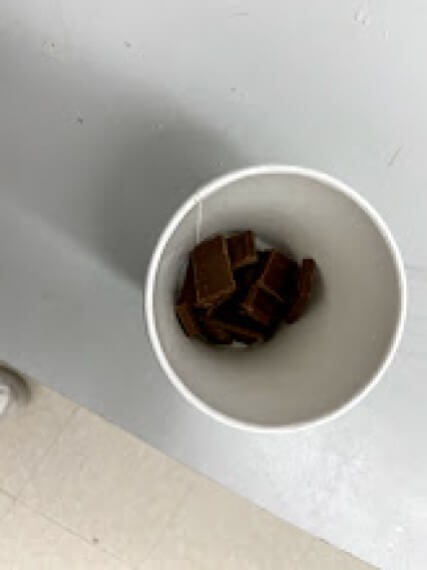
As a final little experiment this week, I attempted to make a chocolate fish in one of my silicone molds. Originally, I started the week with the hope of creating a food-safe fish mold, where I could cast chocolate fish, unfortunately though, I didn’t have access to any food-safe casting materials, and wasn’t able to do this. Despite that, I still thought it would be cool to try casting a chocolate fish, even if I could eat it in the end, so I picked up a Hersheys cholate bar from a grocery store and melted it down in a cup to use for molding a chocolate fish.
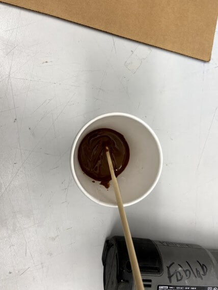
After a bit of heating and stirring, I finally had chocolate melted enough to cast with, and poured the chocolate into my 20T silicon mold, following the same pouring tactics take to pour all of my previous casts. I let this cast harden overnight in our lab, as I didn’t have access to a fridge to speed up the cooling process.
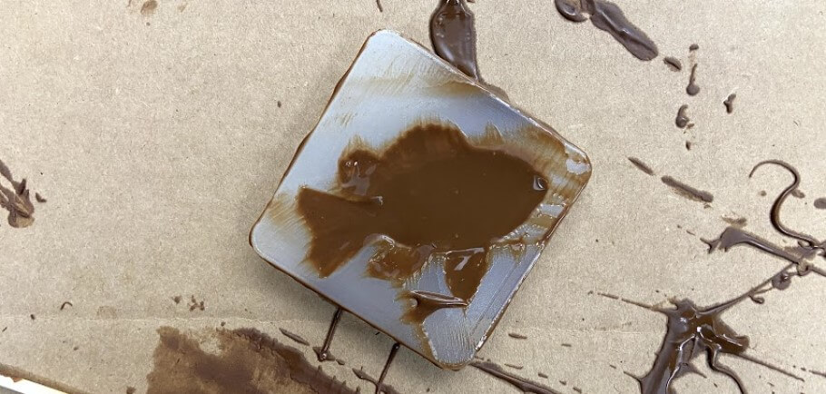
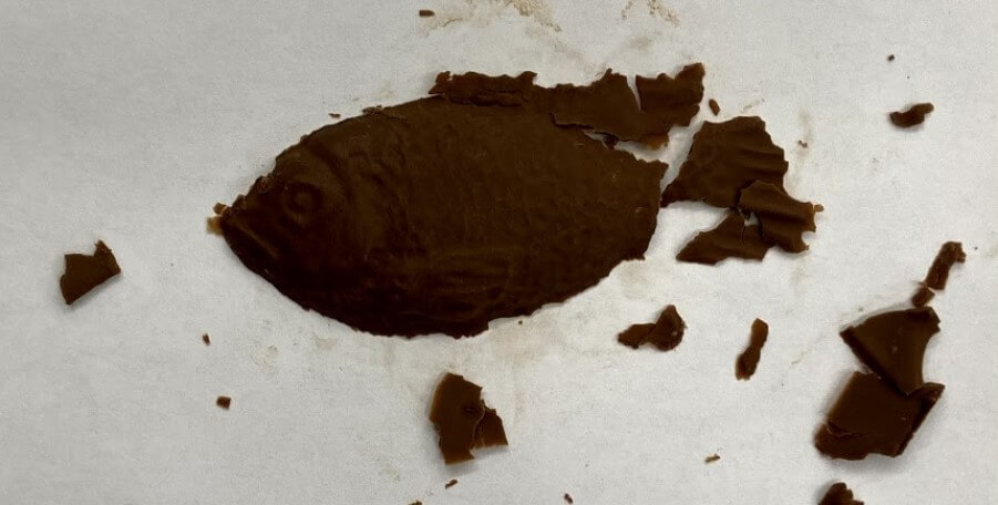
Unfortunately, after all, leading up to the casting of my chocolate fish, the cast yielded a pretty sad fish, one lacking all fins and its tail. I believe this half-fish stems from the thin layers of chocolate that were cast into the mold’s fins and tail, along with the use of a normal chocolate bar, in comparison to a bar of melting chocolate, meant to not fracture as easily once cast.
I finished off the week with my milled 3d fish mold, 4 successful casts, and a pretty sad-looking chocolate fish, all show in the image below.

Group Work
This week we explored the molding and casting process as a group, read the safety data sheet for molding and casting material used, and compared different materials used in the casting process. I worked with one of my classmates, Graham Smith to mill a simple 3d mold, that we went on to cast from later in the week. I also worked with graham on all of this week’s casting, making a silicone mold from 20t and Dragon Skin silicon, and casting our shape from Smooth-Cast 300 in both of them. During the setting of these materials, I also took some time to look through the safety datasheet for Smooth-Cast 300. Click here to view our group documentation site, with this week’s assignment on it.
Downloads
- Click Here to access and download all of my files from this week