2. Computer-Aided Design
This week I worked with computer-aided design tools such as Autodesk’s Fusion 360 and Solidwork’s X design. In addition to that, we built our own Sain Smart Genmitsu CNC milling machines, and Ender 3 3d Printers. (Feb 3)
13-17 minutes
CAD Work
All of this weeks machine-building and modifying (Talked about at the bottom of this page) aside, this week’s assignment was to model a possible final project, taking advantage of computer-aided design tools. I wanted to experiment with many different CAD softwares, to see what I liked, and what I didn’t. Below are my thoughts and uses of the CAD softwares I tried out.
2D CAD
GIMP - Rastor
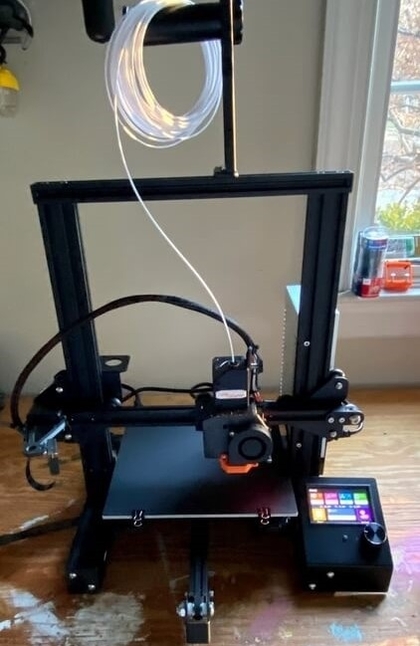
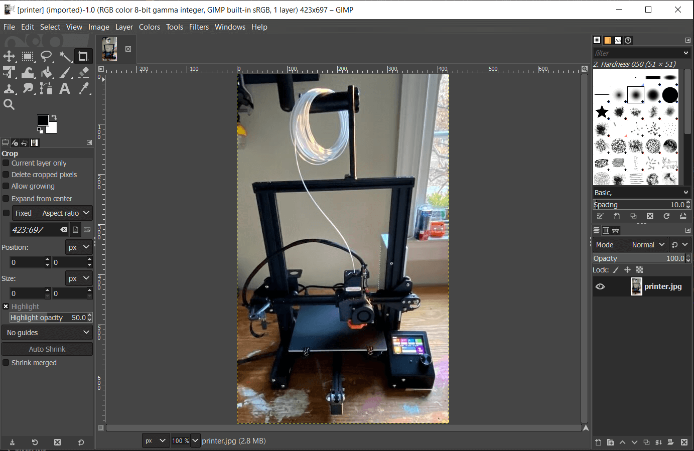
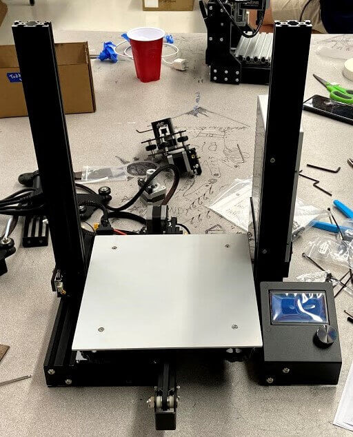
I’ve enjoyed my use of GIMP so far, as it is one of the few softwares I can run on both my Windows laptop as well as my Linux pc. So far I’ve been using the software to view, crop, and resize images for this documentation site your reading right now. The interface is very similar to that of many other 2D CAD softwares, and after a couple of google searches, I was able to find some cool tools I could use for the tasks listed above. Below is a picture of my final modified Ender 3 3D printer, being edited in GIMP.
Pixlr - Rastor
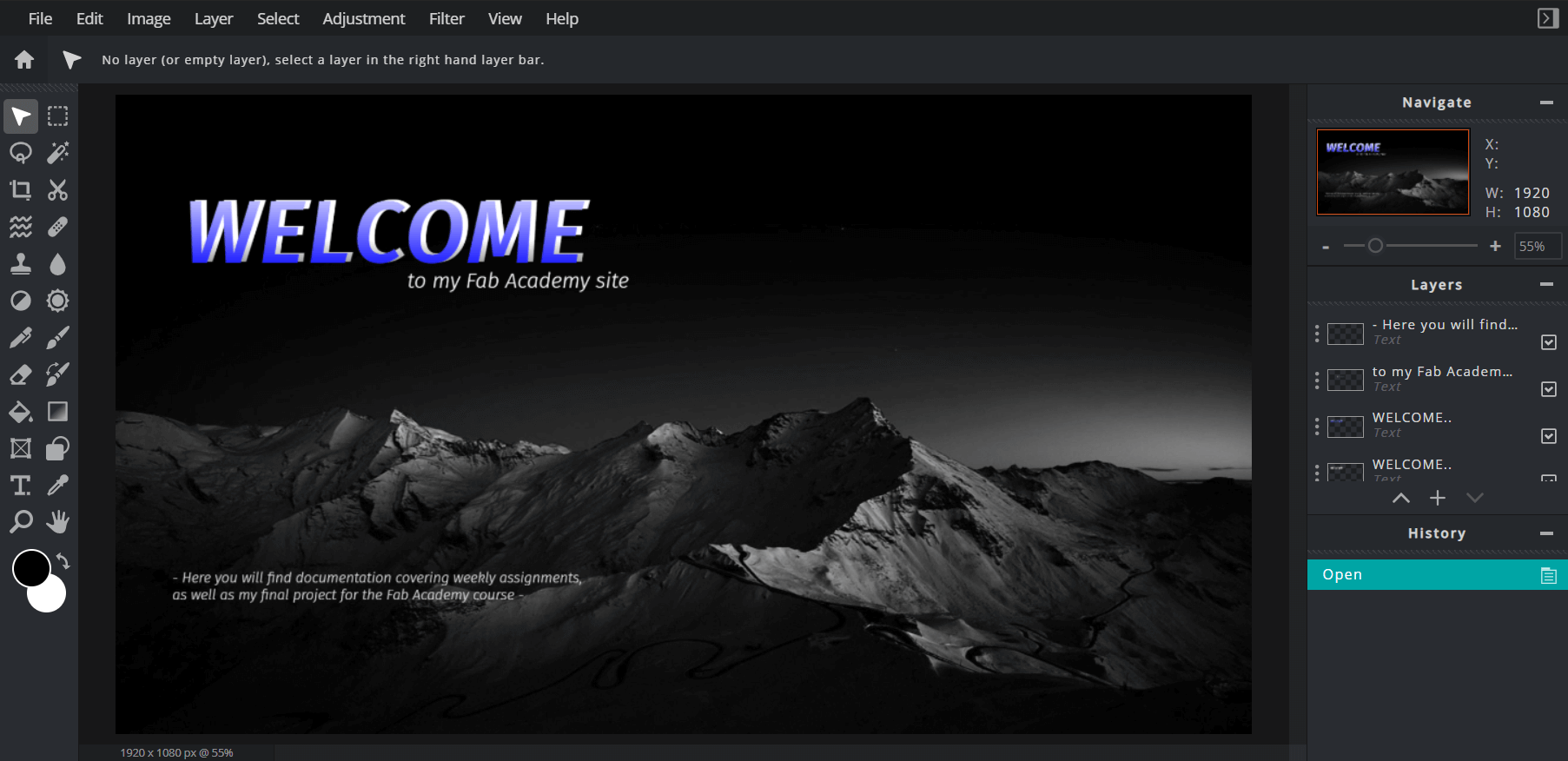
Pixlr is an “Advanced Online Photo Editor”, that works very similarly to Photoshop, but with a much simpler interface and is free to use online. I used pixlr to edit the image used for the background of my homepage on this site. Originally I started working on this image in the Procreate app on my sisters Ipad, however, the interface has a steep learning curve, and I wasn’t a huge fan of working on the Ipad, so when my classmate, Graham Smith, recommended Pixlr to me I decided to start the background over. The original mountain image I used for the background only took me around 10 minutes to edit, and the interface was relatively straight forward to work with, with every tool being labeled. I added a black gradient into the top of the picture and blended that into the mountains to blend the image with the header of my site. I’ve gone back and edited this background a couple of times since I finished the original, adding “Welcome” text, and a small site description. I’m pretty happy with the final project, and my overall experience with pixlr went pretty smoothly.
CorelDRAW - Vector
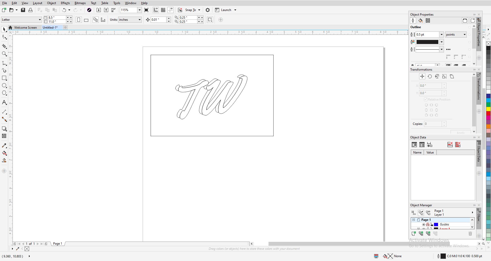
Having access to a Fab Lab since my 8th-grade year, there are many softwares I have started to experiment with to use along with our fabrication machines. CorelDRAW, along with Inkscape are two that I’ve used countless times to design files for our laser cutters. Although both interfaces are very similar, I do prefer the CorelDRAW toolset, as they have a couple of nice AI features, that help in the design process. Despite this, I choose to leave Inkscape installed, as the software is free and opensource, not only making it accessible on my Linux machine but also giving me the ability to install 3rd party plugins. I’ve used a couple of these plugins in the past to assist in my designing of files for our labs Brohter Embroidery Machine. Although CorelDRAW is not opensource, I still choose to use it as my go-to vector interface when it’s accessible to me. I enjoy the small AI features included, such as the Virtual Segment Delete tool witch selects segments of shapes to delete for you, one of my favorite tools in the software. I used CorelDRAW to convert my TW name logo to an SVG file, which I then added to a model of my Final Project.
3D CAD
Autodesk Tinkercad - 3D Design
Just like my prior time in our Fab Lab has exposed me to Inkscape and CorelDRAW, I’ve also spent a portion of time working with 3D CAD softwares such as TinkerCAD and Fusion 360. TinkerCAD is a great intro to CAD, and id compares it to ‘drag-block’ coding, in the sense that you have premade shapes that you can drag onto a workplace, and then alter. TinkerCAD was one of the first CAD softwares I ever used, as it was my go-to for making 3d models for my 3D printer up until my 8th-grade year when I started in Fusion 360. I had a real sense of deja vu when I opened TinkerCAD back up, and I found some cool old models I made way back in middle school. Below is an image of the amount I made for a little medicine syringe in my 8th-grade engineering class. I used this syringe to operate a hydraulic claw on an underwater robot a couple of my friends and I build for our school’s robotic club.
Solidworks xDesign - 3D Design
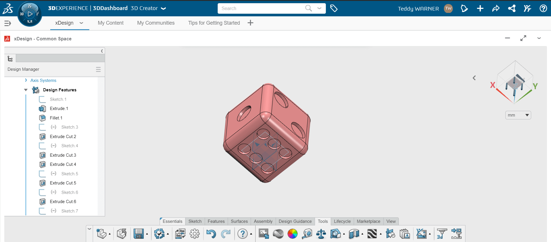
xDesign was my CAD week experiment because although it is not the only new software I looked at this week, the other new software such as GIMP and Pixlr have very similar interfaces to software I am familiar with. The tools in the software are very similar to (or in some cases the same) to the ones in Autodesk’s Fusion 360, a CAD software I am already somewhat familiar with. Over this week I experimented with xDesign, no specifically following any tutorials besides the ones included on the platform. I took a cold plunge into the software and wanted to see what I could learn by myself, just by trial and error and experimentation. After quickly figuring out the softwares movement controls, I attempted to make a sketch and extrude a body, however, I ran into trouble accomplishing this. When I would try to extrude a new body, I would receive a very vague error message saying something along the lines of “cannot form body”. After trying to refresh the page a couple of times, I realized I needed to check the processes for my desired outcome in the pop up extrude box, a simple mistake. I continued to mess with the sketch features of xDesign, and then eventually made a little pink dice, shown in the picture below. This design was nothing special, but I enjoy the features of xDesign and I think it’s cool that they can run such capable software through the cloud. Also, my approach to dive straight into this software gave me some inspiration to do the same with Autodesk’s Fusion 360, a software I am already somewhat familiar with, but that I now would like to become even more comfortable with.
Autodesk Fusion 360 - 3D Design
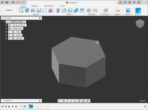
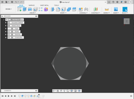
Fusion 360 is undoubtedly the CAD software I am most familiar with, as not only have we spent class time in our lab learning the software sense our freshman year, I’ve been experimenting with and using the software since the summer between my 7th and 8th-grade years of middle school. Although I’ve developed a workflow in the software, and have knowledge of tool positioning and usage, I’ve recently enjoyed following tutorials from Product Design Online. Originally, I got into the software after following his Learn Autodesk Fusion 360 in 30 Days series, and these videos taught me the best practices for the software, and also gave me a nice introduction to useful tools and methods of design in the software. This year, the bioengineering class offered by my school is working through some of the videos from an updated version of this series, and although I spend time in the software relatively commonly, walking through these tutorials with the new Fusion updates has been a pretty good experience, and knocks some of the rust off of some of the practices of my less-used tools. Below are two designs I’ve made following these updated series in my bioengineering class.
Final Project CAD
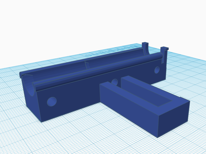
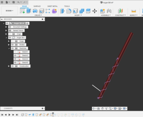
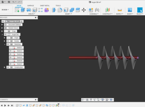
Using the sketches I drew up last week, and some measurements of my window sill, this week I was able to model my final project in Autodesk Fusion 360. I started by recreating my original design sketches in Fusion and then scaling them up to my desired size. These measurements took a while to flatten out, as I want a windowsill box that will fit the entirety of my bedroom window but also keeping it under 6 feet in length for transportation reasons was a priority of mine. After completing these sketches in Fusion, I created new components for each different major body in my design, the windowsill box itself, the two side boxes for the electronics and the water resolver, as well as the front acrylic panels for both of those boxes. The Window-sill box has these two ‘x’ crosses on the front, keeping with the ‘farmhouse’ design style I talked about in my Final Project Concept page. I also took the time to add a nice stained pine look to the model, I’m not sure that this will be the final look I go for, but I thought it looked nice and added to the model for now. For the side boxes on the garden, I chose a nice white ABS appearance in Fusion, as I could see this being a material I would potentially use for the side boxes in the final project.
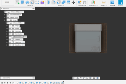
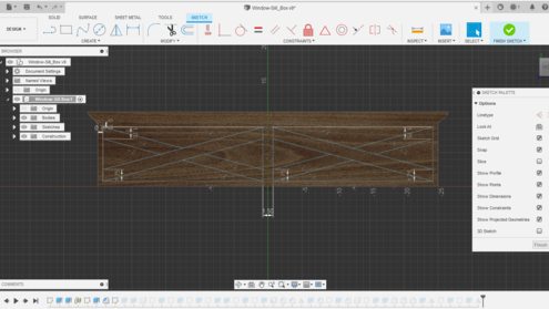
Throughout making this model in Fusion 360, I tried to keep some best design practices in mind that I picked up from the Learn Autodesk Fusion 360 in 30 Days series talked about earlier, as well as some that I’ve picked up from my time on Fusion. I’ve found that for me, the best way to start a CAD model is with a ‘New Component’, and to make bodies in that component. I used that technique when making my windowsill box, by starting with the box itself, and then making another component branched from it for one of the side boxes. Then I was able to mirror this entire side box component from one side of my model to the other, a task made easy by the practice of making components in your model.
Downloads
- Click Here to access and download all of my files from this week
CNC & 3d Printer Building
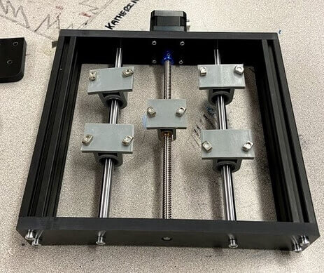
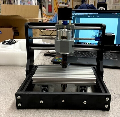
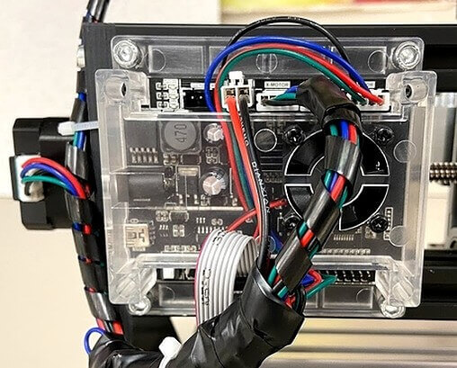
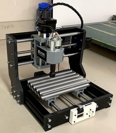
Due to the current Covid-19 restrictions in our school’s county, our lab access has been very choppy. As a workaround to non-constant lab access, each of the Charlotte Latin Fab Academy students is being equipped with a Sain Smart Genmitsu CNC milling machines for PCB milling, an Ender 3 3d Printer and a soldering station for our houses incase of another lockdown. Before starting to work on CAD, we put together the CNC mill as well as the Ender 3 printer kits. The complete documentation and manuals for these machines can be found here Genmitsu CNC Mill, Ender 3 3d Printer. Shown below are some pictures I took while assembling the CNC mill. The whole assembly process from building the frame, to cable management, to GRBL control, took about 2 and a half hours to complete, and being sure to follow the instructions, the assembly process went very smoothly for me with no setbacks.
The process of building these two machines went relatively smoothly, as I only ran into one issue, on the Ender 3 build. One thing to note is the fact that the Ender 3 kit requires a lot less putting together than you would think. The kit come s with a pre-assembled Y-Axis, X-Axis motor housing, extruder, and electronics box. The main issue I ran into with this Ender 3 was linked to the Y-Axis, as I noticed that as I moved the bed back and front, there was a “bump” a couple of times along the way, where pushing the bed would become harder. After trying to move the bed on a couple of my classmate’s printers, I noticed no one else was running into this “Bump”. From prior knowledge, I knew that an issue that many printers like the Ender 3 run into is flat spots on the v slot rollers, causing these “bumps” in movement, and I think it’s safe to assume this is the cause of the “bumps” in my Y-Axis. Unfortunately while building my Ender 3 in our lab, I didn’t have access to extra v-rollers, and I continued with the rest of my build. When I bring my Ender 3 home, I plan on swapping out the faulty v-roller with an extra I have at my house, and hopefully, this will fix the problem.
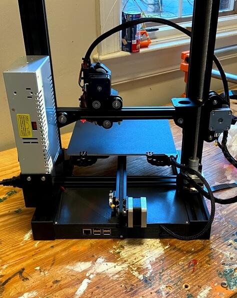
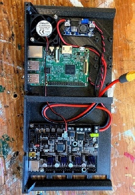
Moding the Ender 3
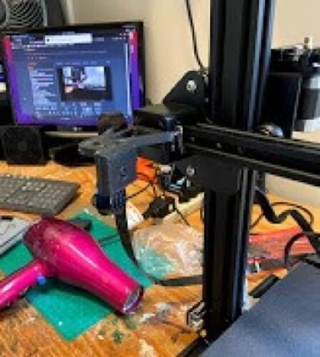
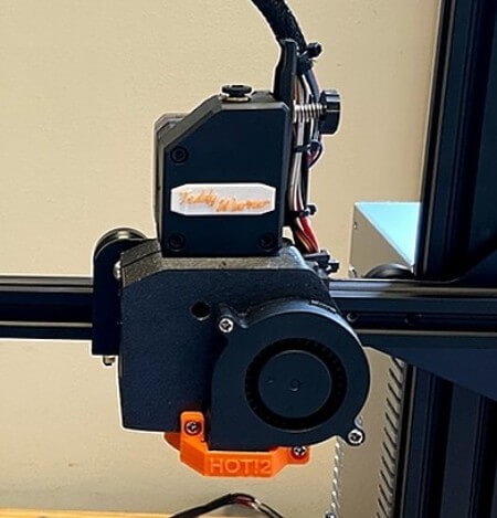
While fixing the fault v-roller talked about in the paragraph above, I took some time to further modify my ender 3 with a mixture of modifications. I upgraded the main bored from the original factory board to a SKR Mini E3 V2, and the original factory screen I switched out to a TFT35 Touchscreen. Following that I added a Bltouch for auto bed leveling, and switched the machine from Bowen to direct drive, with this Thingiverse design. I spent some time adding some customization to the machine as well, giving the direct drive system a little nameplate, and customizing the machine’s firmware for optimal prints and some personal flair, like a colored touchscreen interface with my TW logo on bootup. Finally, I moved all of the electronics of the machine to the rear of the machine using this Thingiverse design. This mod gave the space to add a raspberry pi and a means of power for it, and I decided to take advantage of that and install octoprint for the machine. The octoprint interface allows me to connect to my printer via my local network, and control it via a nice looking interface. I’ve had experience setting up octoprint, running it on all my machines, as well as helping set up octoprint for our fab labs printers, and with this experience, I ran into no major issues while setting up the system. Another benefit of octoprint is the ability to view a webcam feed of your printer, I used this Thingiverse design to mount a raspberry pi camera to my printer’s x-axis as shown in one of the pictures below. All of these modifications were done with parts printed on my Prusa I3 Mk3S+, and electronics I had laying around, making these printer modifications only take around three days to complete, including the time it took to print the parts.
Making these modifications to my Ender 3 was not only a fun activity to take on, I used it as a nice break from CAD and my computer screen. Due to Covid, I spend every other school day at home doing online school, and all that screen time adds up quickly, so having a more hands-on project was nice, and the modifications I got done on my machine should make the overall usage of the machine easier, and reveal higher quality prints.
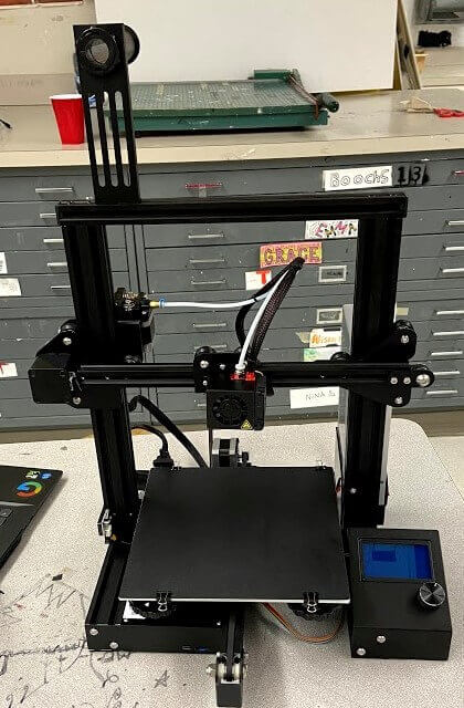
Original vs Modified Ender 3