Week 14. Molding and Casting (Apr 19)
Week 14 Assignment
-
design a mold around the stock and tooling that you’ll be using,
-
mill it (rough cut + three-axis finish cut), and use it to cast parts
-
extra credit: use more than two mold parts
Getting/Refining the Idea
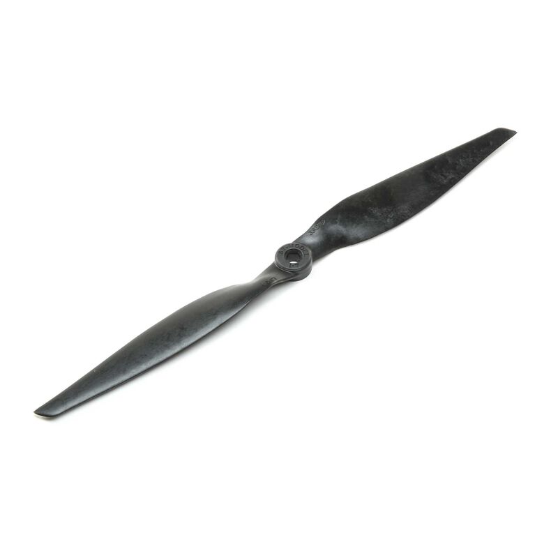
This week, for molding and casting, I wanted to try and mill out a prototype mold for my propellers that I will be using in my final project. This way, I could create 4 casts of that mold fairly simply, so when it came time to build my final project, then thd props wouldn’t be an issue.
Despite having an idea of what I wanted to do, I still wanted research what others did for this week in the past. Of the ones I looked at, Teddy’s fish mold and Jack’s crypto mold stood out to me, and I noted the different softwares and methods they used to design their toolpaths. Notably, Jack Hollingsworth seemed to use Fusion 360 CAM, while Teddy experimented with Aspire CAM. Before this week I had no idea that Fusion 360 had CAMming capabilities, so I now knew about this other option to Aspire Vetric toolpaths.
After doing research, I had a talk with my instructor Dr. Fagan to refine my idea of the prop mold. He proposed to me that I should do a two part mold, which would involve two large blocks of wax being milled with mirror images of the prop, then taking a rubber band and binding the two pieces together, and finally pouring in the molding material into special channels that I would mill out. This was how the idea looked in a sketch.
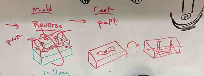
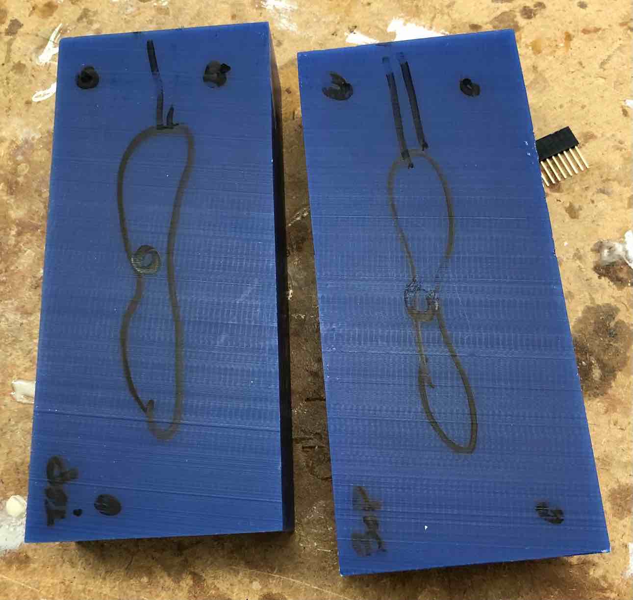
Below is how the two part mold idea would look on the wax. As you can see, there are circles to represent holes for alignment, mirrored prop designs on both blocks of wax, and lines to represent the pouring channels.
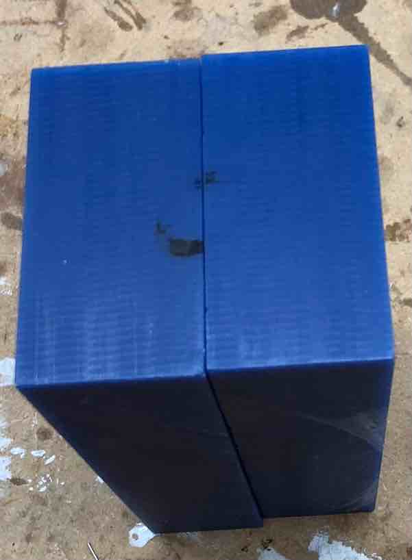
Below represents how the material would be poured in with the two part mold idea. To clamp them together, Dr. Fagan advised me to use rubber bands in order to tightly bound the two blocks of wax together.
Note: While my initial two part mold idea seemed very doable and simple, when I actually went to design it in Fusion CAM, I discovered that each mold would need about 4 hours to mill out. Since the whole purpose of the complication was so that I could have working props for my final project, I decided to abandon the two part mold idea for now, and just try to make a prototype that I will expand on and improve later. Thus I settled on a one part propeller mold idea halfway into the design process.
Design and CAM in Fusion 360
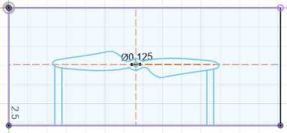
At first, I thought that I wanted to do the two part mold, so I designed two seperate pieces in Fusion 360. I opened up a new fusion file, measured the dimensions of the wax block with calipers, and then drew out the rectangular prism in Fusion. After that, I brought in an image of a propeller from google as a canvas, and used the fit point spline tool to draw around it. Finally I created the channels, which were two rectangles jutting out from the prop design itself. I created two of them so that one of them was for pouring, and the other would be for removing air bubbles in the mold. This is what the design looked like at this point.
I then tried to duplicate this design, but just mirror it so that it could go on the other block of wax. First, I drew two construction lines that divided the propeller in half lengthwise and widthwise. Then I mirrored the propeller over both of the lines, and dragged the resulting sketch onto the other wax block design I created. After mirroring the prop design, I just added channels to the other block of wax, and my 2D designing was done.
It was at this point that I realized that a two part mold was not really a feasible option to get done in less than a week, since the milling alone was taking upwards of 2 - 3 hrs per person, and mine would likely take longer. As a high school student who has to balance school, other extracurriculars, homework, as well as Fab Academy, I was feeling unsure that I could actually complete the assignment in a week. My suspicions were confirmed after a discussion with fellow students Mrs Morrow and Mrs Dhiman, who advised me to just design a one part mold to “get the week over with”, and return to make it a two part mold if needed fo my final project. I thought this was a logical solution to my timing problems and thus pursued this course of action.
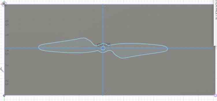
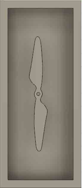
The second time I tried to CAD my propeller mold, I simply followed the same steps, except this time I did not include channels. This is because I would already be able to pour in the molding material with a one part mold, and adding channels to the one part mold would cause the material to leak out. After deleting the channels from the design, this is what it looked like.
After designing the sketch, I simply extruded the propeller design into the wax for a distance of 0.3. This was the final CAD product except for one mistake.
When thinking about this design, at first it made complete sense to me, as I would just have to pour in the casting material into the mold and pull it out to get my propeller. However, the mistake I made was that I forgot to consider the rigidity factor of the material. Since I was milling wax, that was a hard material, and so it required that a soft material be poured into it, since a hard material would just stick to the wax and not be able to be pried out. I wanted not a soft propeller, but a rigid one, and so there was no way for me to get a hard final product with this “negative” image that cut into the wax. Luckily, I noticed this fact before I started creating my toolpaths, so it could be easily solved in the design.
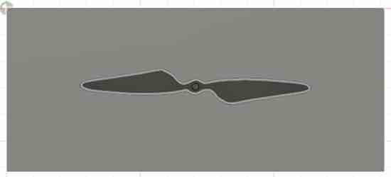
The solution I came up for this was to create a positive image of my propeller first, then pour soft mold material over that to create a flexible mold, and finally pour tough casting material into that to create a rigid propeller. In other words, I couldn’t do hard -> hard or soft -> soft, but I could do hard -> soft -> hard. Redesigning the propeller wasn’t too difficult either, as I just took my already sketched propeller, shelled out the interior of my wax block, then put the sketch on the bottom facing up, and extruded it upwards or “positively”. After the redesign my true final CAD product looked like this.
Finally with the CAD side done, I could move onto CAMming the toolpaths. Before this week, I had only ever used Aspire Vetric for generating toolpaths, and those were only ever used on the shopbot large CNC machines. Initially I thought that my wax block was too big for the small Bantam mills, and that I would have to use the shopbot CNC machine just like Teddy Warner did. This turned out not to be the case as my wax block fit on the new Bantam Tools desktop milling machine, but not the Bantam Othermills.
With this discovery I decided to explore Fusion CAM instead of using Aspire for a few reasons.
-
My design was in Fusion 360 so it was easier for me to use Fusion CAM in case my design needed to be changed
-
I wanted to explore something new, and I had heard Fusion was better on the Bantam othermills
-
Fusion 360 was my go to software for anything CAD related, and I wanted to expand my knowledge of the software.
After deciding to use Fusion CAM, I began to explore some resources for learning how to use it. Our instructor, Dr. Taylor, actually gave us a brief presentation on Fusion CAM prior to this, so I went to go look at the links he gave me. This article on Fusion 360 CAM with Bantam Tools was exactly what I needed, and I pretty much just followed their instructions all the wya.
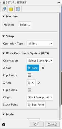
I began by going to the dropdown in the top left corner of the design file and selecting the “manufacture” workspace, instead of the “design” workspace. Then I went to setups and hit create new setup, which brought up a popup on the right. Next I worked on orienting my axis, which involved telling the software which direction was which. I ended up selecting the top plane of my prop mold as my z axis, and the x axis arrow as my x axis. It automatically put the y axis, I verified that my axis were correct, which they were. Here’s how it looked.
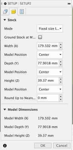
Next it was time to setup the stock, or setting the settings for the material that I was miling out. I set the dimensions of the block, and chose an appropriate box point as my origin. Here’s how it looked.
Now my setup was finished, and it was time to create the toolpaths. First I had to import the Bantam Tools tool library into Fusion 360. I downloaded this, then imported the .json file (for Mac users) into Fusion 360’s internal tool library. I found success.
Finally it was time to create the actual toolpaths, which I followed the instructions on that same website to create two 3D Adaptive Clearing toolpaths, one for smoothing, one for roughing. Both toolpaths were similar, but I just used a 1/8 inch flat end mill on the roughing, and a 1/8 inch ball end mill on the smoothing. I went to fusion and found the 3D Adaptive Clearing toolpath, then basically just repeated this process twice.
- With the Tool tab opened, click the Select button next to the Tool label. Use the tool selection window to choose an appropriate tool. (I used a 1/8 inch flat for the roughing and 1/8 inch ball for the smoothing)
![]()
-
Back in the Tool tab, ensure that the Coolant menu is set to Disabled and set the feeds and speeds for this toolpath (these were preset for me when I selected the tool so I didn’t have to do it)
-
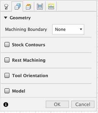
Switch to the Geometry tab. Deselect Stock Contours to ensure that the toolpath mills the entire piece of stock configured. Disable Rest Machining to disregard previous toolpaths. Leave Tool Orientation and Model unchecked.
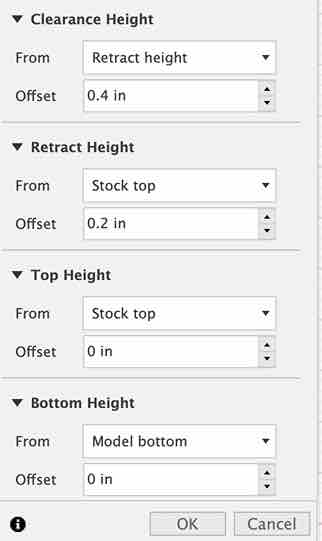
- Click the Heights tab. For a 3D Adaptive Clearing operation, Fusion 360 will automatically mill the entire region from the top of the stock to the bottom of the model. Leave this tab as is.
-
Switch to the Passes tab. The most important settings here are Optimal Load and Maximum Roughing Stepdown. These set the amount of material the tool will cut on each pass. Set values for both that are no more than half the diameter of your tool. (Since both my tools were 1/8 inch or 0.125, I used values of 0.0625 inch for both Load and Stepdown)
-
If you don’t plan to set up a separate finishing pass, uncheck Stock to Leave. (I checked this box since I did want to set up a finishing pass)
-
With all of these settings entered, click OK.
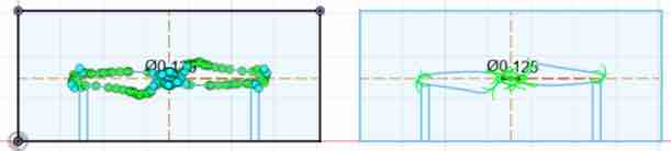
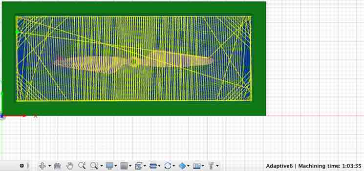
Finally with the toolpaths generated, I wanted to simulate them. This is what it looked like when I did.
After being satisfied with the toolpaths, I saved them as gcode files by following this process on the website
-
Select it in the Browser panel and click the Post Process button under Actions.
-
In the Post Process panel that pops up, set Post Processor to “othermill.cps - Generic Othermill (Otherplan).”
-
Under Program Number, enter a number. And for Units, select Document Unit. Then leave “Minimize tool changes” unchecked.
-
Uncheck “Open NC file in editor,” and leave all the Properties values alone.
-
Click OK and choose a destination to save your file, making sure that it has an .nc extension (I chose my downloads folder)
The CAD design and CAM toolpaths were finally finished and I saved them to my drive for future access.
Milling the Wax
For the milling of the wax, I used the Bantam Tools Desktop milling machine, something I had never used before. However, the setup process was very similar to the Bantam Othermill so it wasn’t too difficult, not to mention that it was more self guided and intuitive to learn than the Othermill setup. I used a workflow provided to me by fellow student Mrs. Morrow when setting this thing up.
I’ve already covered milling a few times before in my documentation, so here I’ll just go through a quick rundown of the process. These are the tools I used for this process
Tools: - Bantam Desktop CNC Milling Machine - Milling file for wax - Blue machinable wax - ⅛” Ball Nose End Mill - 1/8 inch Flat Nose End Mill - Double Sided Nitto Tape
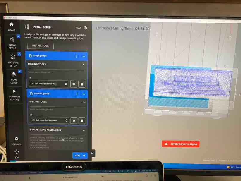
This is the workflow I followed.
Initial Setup
-
Select Open File
-
Load your file
-
Install Tool (1/8 flat for the roughing and 1/8 ball for smoothing)
Material Setup
- Measure your wax blank and record measurements (7.067 in x 3.067 in x 1.55 in in my case)
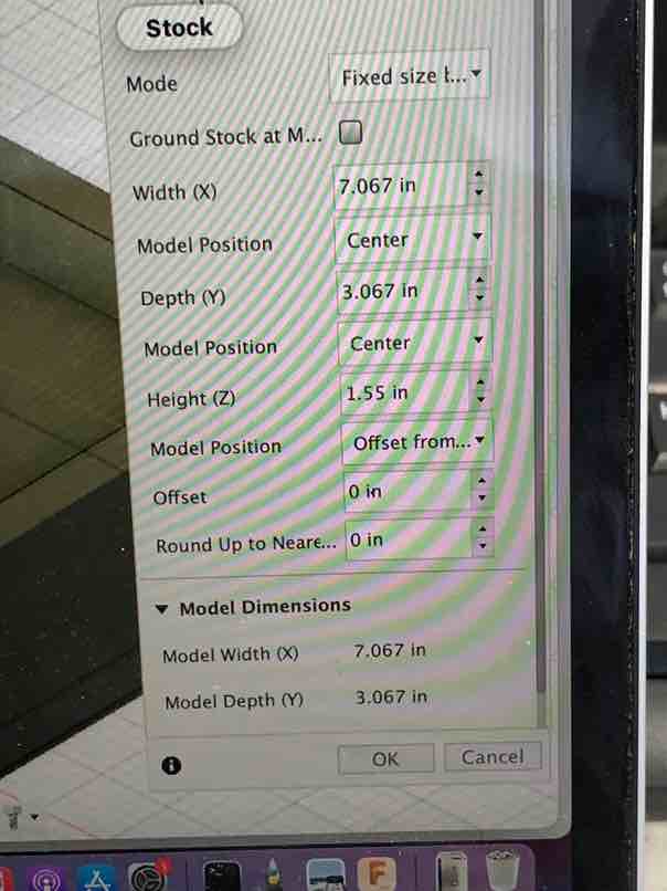
These are the dimensions of the wax I was milling.
- Put double-sided Nitto tape on the bottom of the wax blank, and press the wax blank down in the bottom left corner of the PCB Bracket
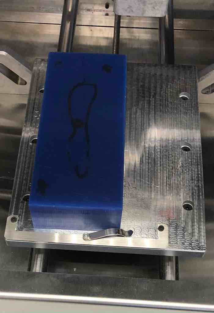
This is the wax being attached onto the bed of the milling machine.
-
Input your measurements being careful to note units (mm or inches)
-
. Material Offset is the thickness of of the Nitto Tape (0.001 in in this case)
Plan Setup
-
Verify that your file is in the Blue Banner at the top of the Plan Setup
-
Set the X and Y coordinates so that your design is accurately placed in the material on the screen
-
Adjust Z to the appropriate height so that from the SIDE view the milling starts at the top of the material
Summary Run Job
-
Review Machine Summary
-
Review Plan Summary Box
-
Be sure “Select For Milling” slider is blue
-
Verify Tool Selection and Plan Placement
-
Go through the tool location process (no need to do bitbreakers on this machine)
I started out with the 1/8 inch flat end mill. First, I put it into the collet.
Then I located it, just like I would on the othermill.
Next I repeated the same process with the 1/8 ball end mill after it was done milling the roughing pass. This is how it looked.
Start Milling
- Decide if you want to ‘Mill SingleFile’ or ‘Mill All’ and press the appropriate button to begin the job
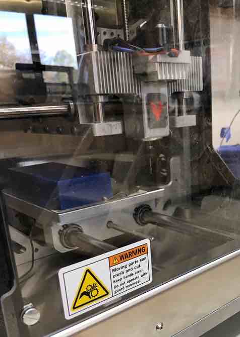
This is the wax at the beginning of the roughing pass
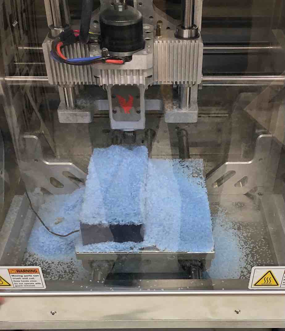
This is the wax at the end of the roughing pass
- Watch the mill to make sure everything goes well
Unfortunately, when I was almost done with my smoothing pass, I encountered this error about the tool being retracted too far into the spindle.
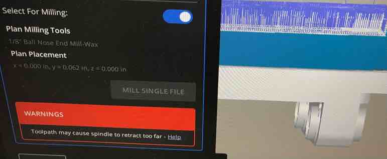
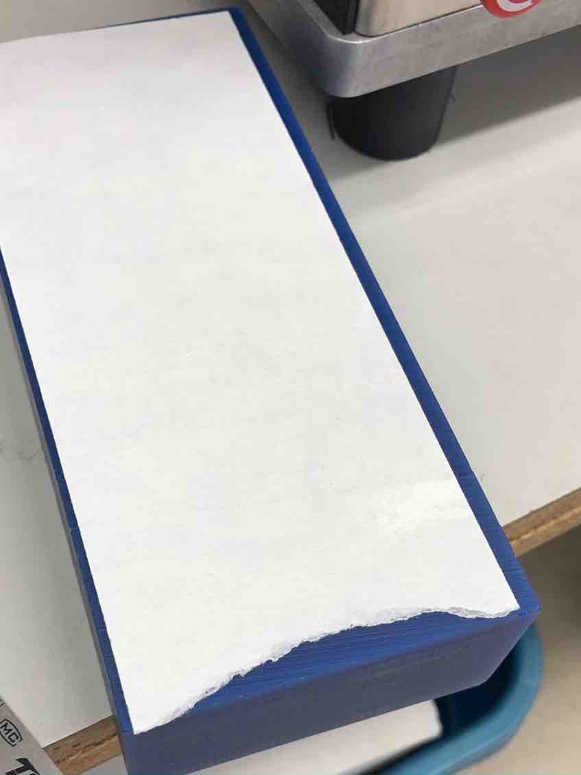
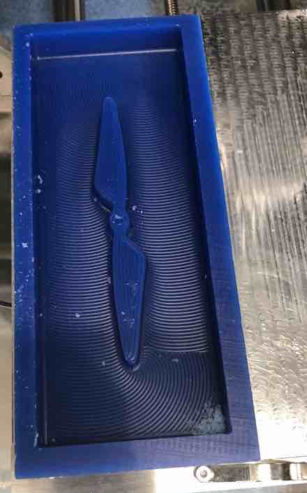
This is probably because when I inserted the tool into the collet, I inserted it too far in, and so it caused this error. I called our lab’s teacher, Mr. Budzikowski, over to check it out, and he thought that it was fine if I just stopped the smoothing pass altogether, since it had pretty much already finished. Thus I stopped the job. This was what the final wax mold looked like.
Vacuum the Machine
This is me vaccuming the machine to get rid of all the excess wax.
My wax mold was finally done.
Molding and Casting
For the actual molding and casting for this week, there were two main parts: using soft material to get a flexible mold out of the wax mold, and using hard material to get a rigid cast of a prop out of the flexible mold. Because I had already done this week’s group assignment, I had some experience with molding and casting already.
I had to repeat this process twice 1. find the right material 2. pour parts A and B and mix them together until a reaction forms 3. wait until the cure time is up 4. pop out the solid material
First I started with the soft material, which I decided to use Mold Star 20T for. I was recommended this material by fellow student Mrs. Morrow, whose page I have already linked prior.
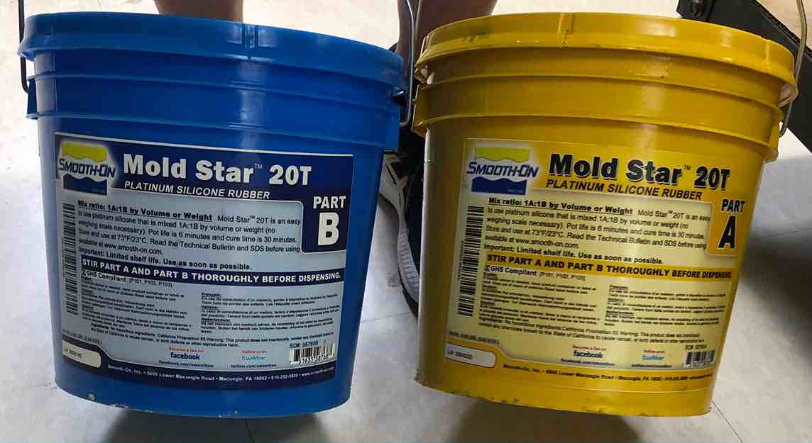
Here is the datasheet for this material
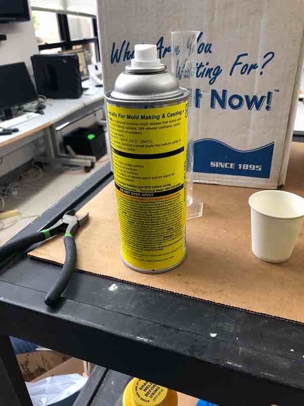
I began by looking at the ratios of parts A and B, and saw that it was one to one. Then, I sprayed the wax mold all over with grease, so that it would be easy for me to pry out the mold once it hardened.
Next I began mixing the two parts together. After a few minutes, I determined that it was a good time to pour the silicone into my wax mold. This is what the mold looked like with the pour in it, and I was pounding my hands on the table to remove air bubbles.
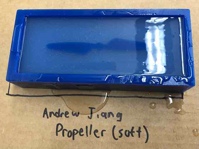
After waiting about 30 minutes, I removed the hardened but flexible rubber from the wax. At first I couldn’t get it out, likely because some of the rubber was stuck.
Then Mrs. Dhiman, a fellow student whose page I’ve already linked prior, advised me to take the backside of tweezers and try again. I found success.
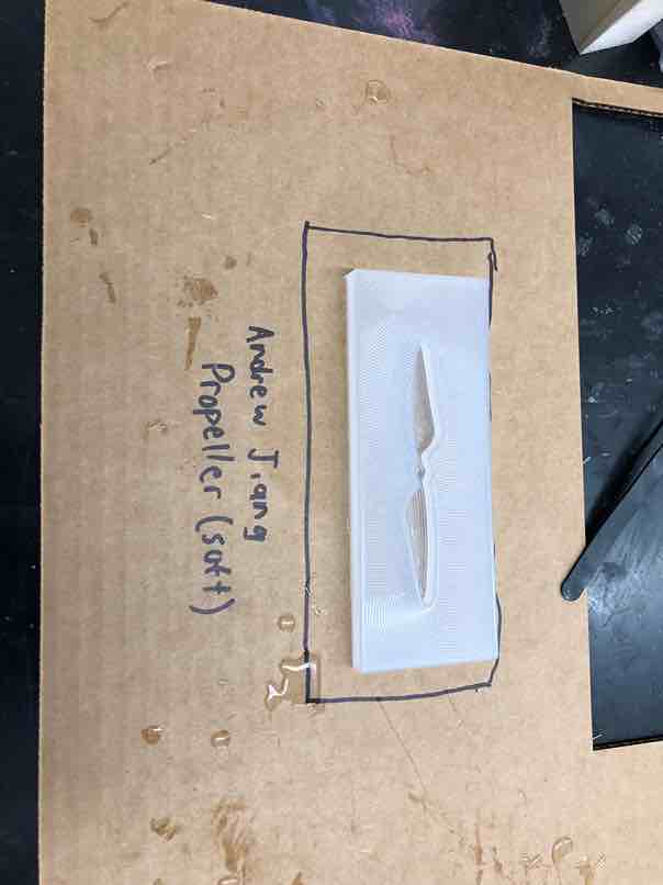
This is what the mold looked like after it was taken out of the wax.
After that it was time for step two, pouring the hard material into the soft mold. I decided to use Smooth Cast 300Q, which was once again recommended to me by Mrs Morrow. I also agreed that this was the best option, since this was the material that had hardened the quickest in the group work.
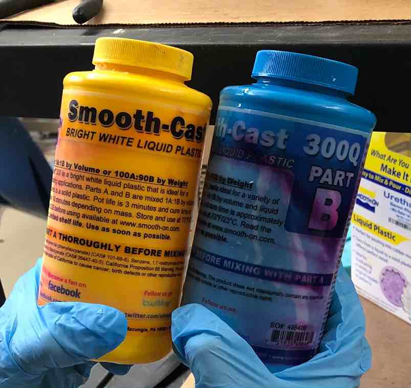
Here is the datasheet for this material
Next I sprayed the soft mold once again with grease, and began mixing the two parts of this material. Compared to the soft material, this reaction was most notably exothermic and the quickest, as it became very hot and solid to the touch after a very short time.
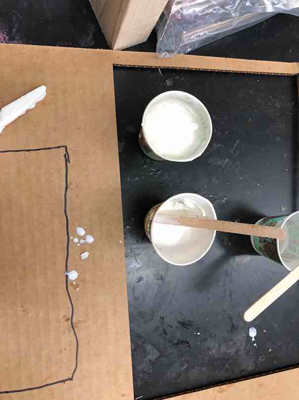
Next it was time to pour the hard material into the soft mold.
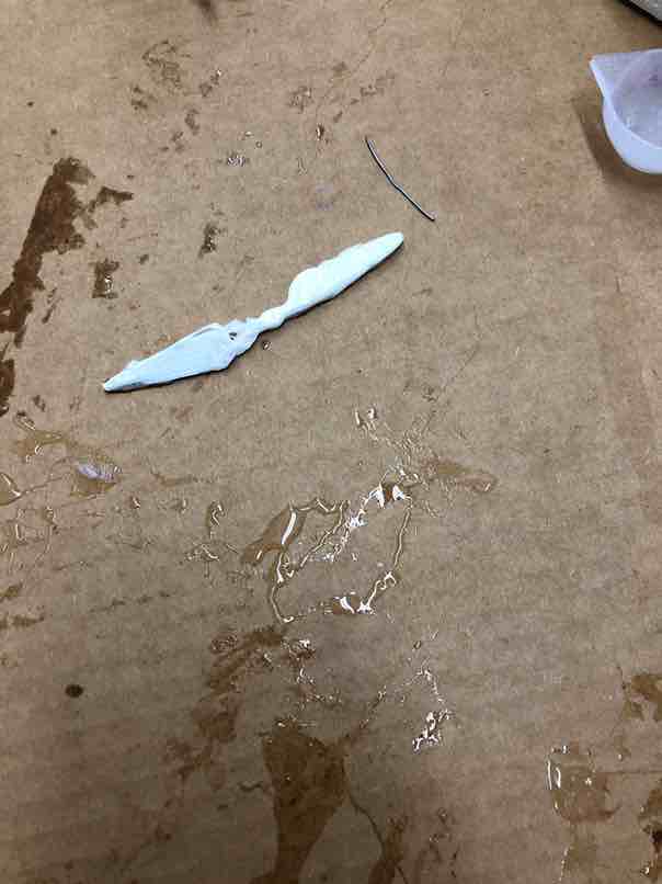
The first time I tried the pouring, I completely underpoured on one side and overpoured on the other. Also, I prematurely removed the cast from its case, resulting in a liquidy mess.
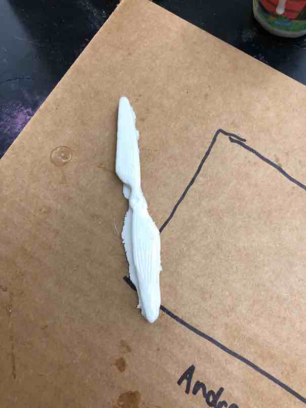
Next time, I still underpoured on one side, but it wasn’t that noticeable, and I also waited long enough for it to fully solidify.
Finally, I wanted to sand off any impurities in the mold, so I took some sandpaper and rubbed it against the cast until it became smooth.
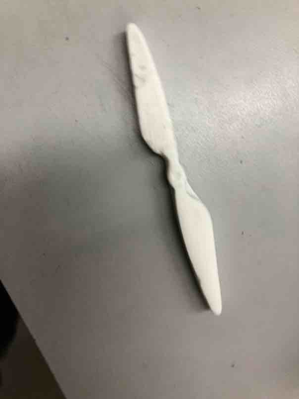
Overall, one improvement I could make is in my pouring, such that the propeller doesn’t turn out unbalanced. But I am still very proud of what I accomplished this week, especially since I’ve never done molding and casting before.
Week 14 Group Work
This week our group task was simply to compare the safety data sheets for each of the molding and casting materials, and then make and compare test casts with each of them. My subgroup consisted of Jack, Nick, Aarush and me, and we tested the casting of 6 materials in total: Urethane 666, Task 3, Moldstar 20T, Dragon Skin, Smooth Cast 300, and Task 8. My role this week was mainly reviewing the datasheets and helping Jack and Nick with the casting by telling them the information for each material, such as pot life, pour ratio, cure time, etc. I also summarized the groups results for each material on the group page.
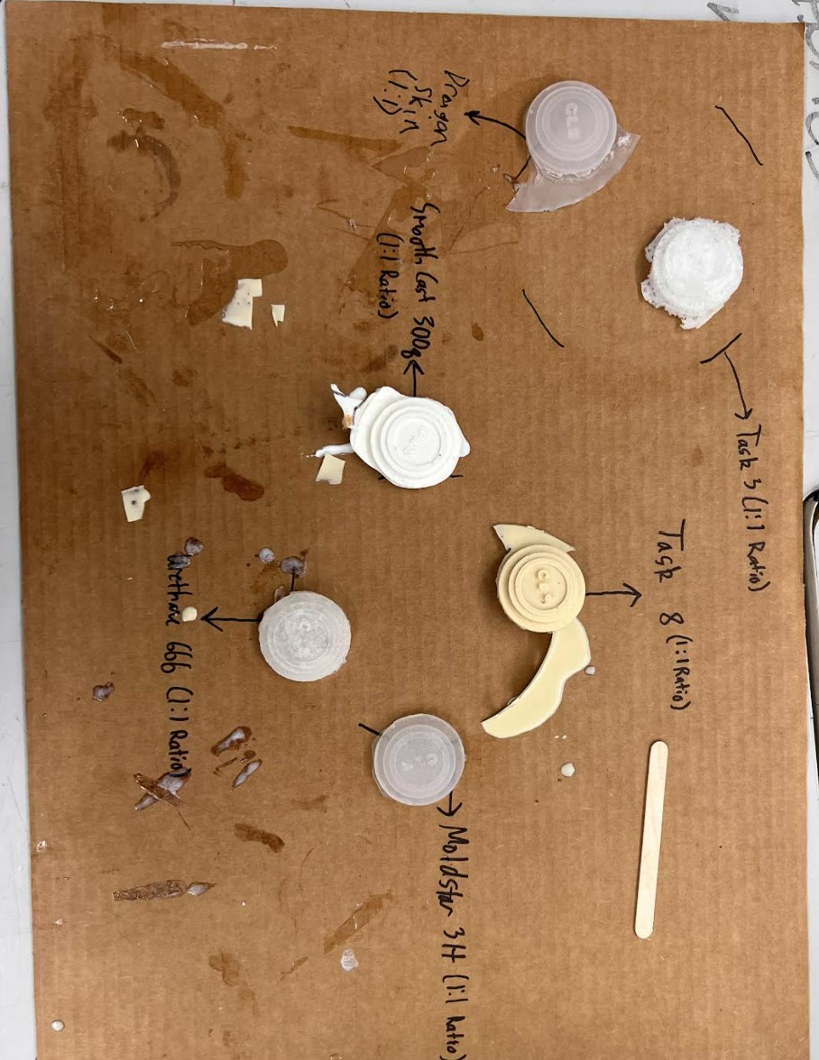
Here is the summary from the group page.
Overall the molding and casting materials can be split into rigid and flexible ones, or those that are bendable after hardening and those that aren’t. Out of the ones we tested, which were the Task 8, Smooth Cast 300, Dragon Skin, Moldstar 20T, Task 3, and Urethane 666, all of the materials utilized a 1:1 ratio between parts A and B, with varying cure times and pot lifes. For example, a material like Task 8 has a pot life of 2.5 minutes and cure time of 15 minutes, which is relatively short compared to a material like Dragon Skin 10, which has a pot life of 8 minutes and a cure time of 75 minutes. In addition to varying cure times, some of the materials release more heat than others in the chemical reaction, most notably the Task 8 and Smooth Cast 300. The ones that were rigid were Task 8, Smooth Cast 300, and Task 3, the ones that released the most heat. The flexible ones were Dragon Skin and Mold Star 20T, with Urethane 666 being somewhat flexible.
You can find more information about each material on their respective datasheets linked above.
You can find more information about the group work for this week on the group site.
Week 14 Files
Click here to access my files for the week.