9.0 Molding and Casting
This week, we were asked to design a mold around the stock and tooling that we will be using. We have been asked to mill it (rough cut and 3-axis finish cut), and use it to cast parts. For “extra credit”, we can use more than two mold parts.
From the early discussions of my project, it has always been my plan to design a mold of my Falcon-9 rocket with its boosters. My plan was to mill it out (using milling wax as the medium) twice (or repeating the process twice) and use hard/durable resin in it. As I discussed this with colleagues/classmates Nidhie Dhiman and Scott Moulton, they posed the idea that I make molds of the silhouette of crowds of people watching the Falcon-9 rocket launch. I began to explore images from Google searches of “crowds cheering silhouette”. Sifting through many of them, Scott Moulton suggested I make molds of my husband and grandson watching the rocket launch. Nidhie Dhiman suggested using exact silhouettes of the two of them, and I began to design this.
Designing Silhouettes
I refined a Google search, and I eventually found this image. I tried to copy the image, bring it into Corel Draw and trace a bitmap of it. But when I did this, the clear features kept getting blurred or deleted.
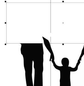
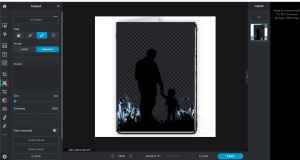
Scott Moulton suggest that I use a website called Pxlr, and he showed me how to import the image and start removing unwanted exterior pixels in the silhouette. The images below show my process of modifying the silhouette in Pixlr.
| Images of Experimenting with Pixlr | Description |
|---|---|
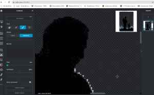 |
Removing pixels located near the face. |
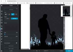 |
All pixels around the grnadfather and grandson are removed. |
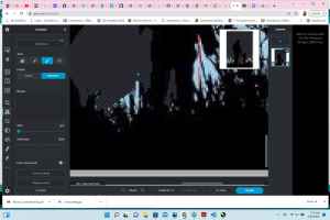 |
Starting to remove pixels from the middle grass area. |
 |
Removing and re-shaping the grassy areas on the exterior of the legs. |
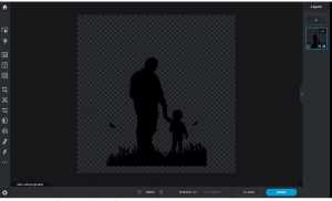 |
Finalized silhoeuette, ready for mold design. |
 |
This is how the file turned out in Pxlr. While the silhouette outline is extrememly faint, I think I ccould have modified it in Corel Draw to work. |
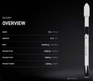
On Thursday, March 24, I wanted to start designing the mold for my silhouette, and this caused me to have to think about the size that I would make it. I realized that– if I were going to make all items in my object proportional, then I needed to plan out the size of my rocket at the same time. I thought about designing and 3D printing my Falcon-9 rocket using the resin printer in the Charlotte Latin School Fab Lab. In my proportionality quest, I needed to know the dimensions of the Falcon-9 rocket. Once agaian, I did an Internet search, and I found the SpaceX Falcon 9 dimesions on this actual SpaceX site. The length (height) of the Falcon 9 rocket is 70 meters (or 210 feet)– which I converted to 2,520 inches.
I began to do the proportionality calculations based around my husband’s height–75”. I set up the following equation based on an 8” Falcon 9 rocket. (This is slightly under the max Z value allowed in the resin printer in the Charlotte Latin School fab lab).
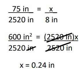
The calculation shows how big (in inches) that the silhouette of my husband would need to be, and my grandson in the silhouette would be even smaller! After trying out more rocket:husband dimensions, I found that by making the rocket 20”, I could get my husband’s silhouette height to be 0.59”. While this was better, I still felt it was too small. If I created the rocket to be 20”, then I would have to print it in 3 parts in our resin printer, and the overall size of my device was getting very large.
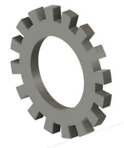
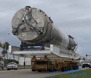
On Friday, March 25, I had a visit from colleague/classmate, Nidhie Dhiman. As I explained my dilemma to her, we started to brainstorm design modifications around the horizontal movement of my project. I showed Nidhie Dhiman how SpaceX now transports their rockets to the launch area. NASA used to use a crawler for the Space Shuttles, and I had originally wanted to use this slow-moving process in my design. However, when I researched (a few weeks ago) what SpaceX uses, I found that they use a modified large truck to transport it to the launch site, and the truck then hydraulically lifts the rocket into its vertical launch position. We used simple objects (small boards and scrap pieces of wood) to visually see how this could work in my design. That’s when Nidhie Dhiman came up with the idea to cast and mold the tires on the truck using silicone! I was so excited about this idea; I searched through the plastic bins of lego and K’NEX pieces stored in the Charlotte Latin School Fab Lab, and eventually settled on the one below.
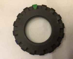
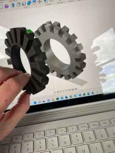
This tire seemed to be the most like the one in– what I now knew to be called– the SpaceX Transporter Erector Launcher. To see how the “teeth” on one side of the tire aligned, I placed two rulers intersecting over the tire, and I learned that the teeth were made up of diameter lines that cross-sected the entire circle. This would prove to be valuable information later on in the design.
I began to design the tire in Fusion 360.
Designing the Tire
Before I could start my design in Fusion 360, I had use callipers to measure the dimensions of the tire. I found the inner hole diameter (where the wheel and axle would come in contact) to be 50 mm, and the outer diameter of of the tire to be 88 mm. The thickness of the entire tire was 14 mm. To design the tire, I used Fusion 360, and the following table shows the screenshots and descriptions of my work.
| Screenshot | Description |
|---|---|
 |
As I began designing, I started with a cylinder, and I intended to make this original cylinder the middle/hole of the tire. Next, I wanted to make a larger circle around it, and extrude it to the needed height. As I examined the tire further, I actually wound up abandoning the use of cylinders because I realized that the two sides of my tire were not symmetrical. I would have to design each side individually. |
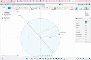 |
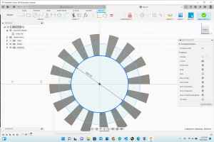
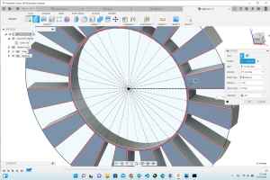
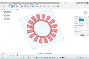
I created the external circle with a diameter of 88mm. I counted that there were 16 “teeth” and 16 indentations between teeth on each side of the tire. (I had to place a piece of green tape on it to mark the tire for counting the teeth). I divided 360 degrees/ 32 (pieces of the circle) and got that the internal angles had a measure of 11.25 degrees. |
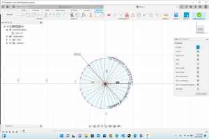 |
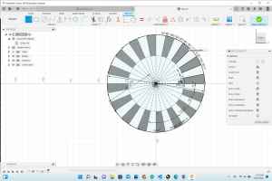
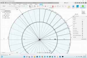
Using “construction lines”, I divided the circle into 32 equal wdges with angles measuring at 11.25 degrees. |
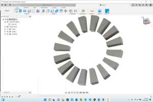 |
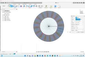
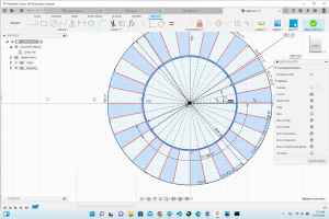
For one side of the tire, I selected every other “pie wedge” and extruded it to 7 mm (half of the overall thickness of the whole tire). |
 |
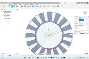
On the opposite side of the tire (a new design altogther), I repeated the first three steps and placed another circle at the center with a diameter of 60.5 mm. |
 |
I redrew the 11.25-degree “wedges of the pie” as construction lines. I drew permanent lines onto the construction lines between the 88mm-circle and the 60.5-mm circle. |
 |
I selected every other “pie wedge” and extruded them -7 mm so that they were in opposite directions from the first side. |
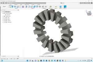 |
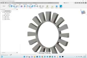
Both sides of the tire were symmetrical at this point– alternating in their “wedge” pattern. |
 |
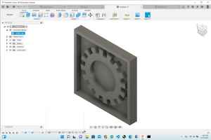
I created an offset plane on the front face, and I drew a new circle on it with a diameter of 60.5 mm. I then extruded this new portion of the design to 14 mm (the overall thickness of the tire). |
 |
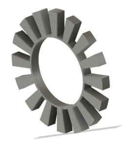
This is what I thought was the “completed tire”, but I realized the two sides were not identical. I backed up in the “timeline”, trying to determine the best place to make modifications. |
 |
At the Charlotte Latin School Fab Lab, there are 13 students, and three working desktop CNC machines. At this point in my design, I decided to make a cast/mold of only half of my tire. This required me to have to design 1/2 of the tire again by itself. I repeated the steps above, with the “thicker” ring. (I felt that a 3-mm ring on the internal side would make the cast/mold very unstable; so I picked the side of the tire with a ring having a larger surface area). Before I could make this new 1/2-design, I wanted to finish the new side so that I could refer back to this design with my final project. |
 |
Once again, I selected every-other pie wedge (measureing 11.25 degrees each). |
 |
I extruded the pie wedges 7 mm. |
 |
I added another circle with a diameter of 53 mm. |
 |
I clicked on the 50-mm circle and the 53-mm circle (together forming a 3-mm ring), and I extruded this “internal ring” 7 mm. |
 |
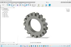
This shows the completed side 1 of my tire (separate from side 2). |
 |
This shows the completed side 2 of my tire (separate from side 1). |
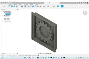 |
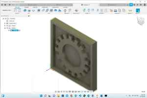
To turn side 2 of my tire into a mold, I had to create a box around it. I then added a slightly larger box around the first one, and I extruded the “box ring” 10 mm. This enabled the sides to be 3 mm taller than the wheel, and allows for the liquid to pour over top of the soon-to-be milled out tire. |
 |
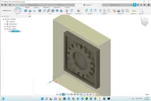
As I made the sides higher, I really doubted how to make this part of the mold. This image shows my “logic”/thought process, as I tried to determine how the hardening liquid would generate a cast. At first, I thought I had to make it a hole; but I was reversed in my thinking. |
 |
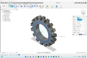
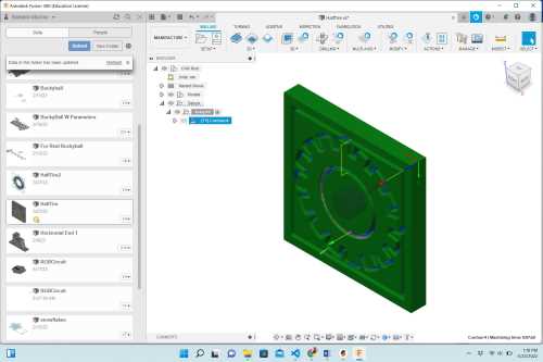
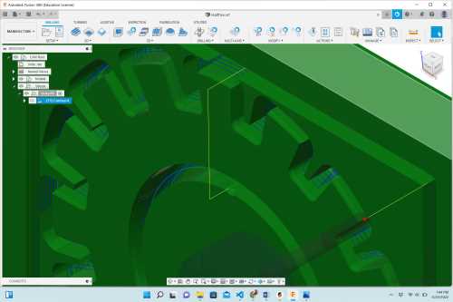
This is the final design that I planned to mill on the Bantam Desktop Milling Machine in the Charlotte Latin School Fab Lab. |
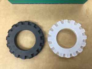
The following image shows the comparison of the actual tire and my designed tire.
Setting up the CAM File
On Sunday, March 27, I went in to the Charlotte Latin School Fab Lab to try to mill my mold for casting and molding. When I arrived, four other students (Nidhie Dhiman, Aaron Logan, Alaric Pan, and Andreiw Jiang) were already there. They suggested that in order to prepare my design for milling, that I follow the instructions in Bantam Tools and Fusion 360.
As I set up my design (in the Manufacturing tab of Fusion 360), I listened as Alaric Pan discussed his design with others. He was making a 2-part mold, and I really wanted to change my plan and make both sides of my tire. I spent about an hour modifying my design so that I could make it a 2-part mold that included the vent and “pipeline” for adding the material. Hearing that the others were creating jobs for the desktop milling machines that were multiple hours in length, I decided to abandon the 2-part mold. My tire was already larger than the objects designed for milling, molding and casting. I feared that my job was going to take too long and would delay others in our Fab Academy group (of 13).
The following table contains images and descriptions of some of the CAM file setup.
| Image | Description |
|---|---|
 |
I created a square base under the tired design and added a wall. |
 |
I placed the design into the graphic material (wax in Fusion360). |
 |
I downloaded the tool library and selected the correct bits for each pass. |
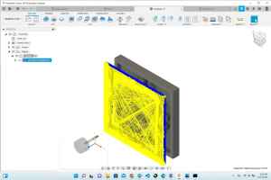 |
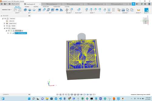
This shows the first tool path generating the setup and predicted mill time. |
 |
As the file was processing, it kept “getting stuck” at 57.3%. Thinking there was something wring with the wi-fi at the school, I restarted this tool path processing three times. On the third time, colleague/classmate, Nidhie Dhiman looked at my settings and found an extra 0 in one of the fields. |
 |
This is the fourth attempt at processing the two toolpaths. The first one processed well, but the second pass kept freezing at 73.6%. It was very close to finishing, but it would never finalize. I decided to look through the settings again. |
 |
Once again, the toolpath process could not be finalized and got stuck. This time, I noticed that the units were wrong in selecting the tools. Also, Nidhie Dhiman informed me that I should not be halving the bit diameter when using the 1/16” bit. |
 |
This shows the toolpath being correctly processed– finally. |
 |
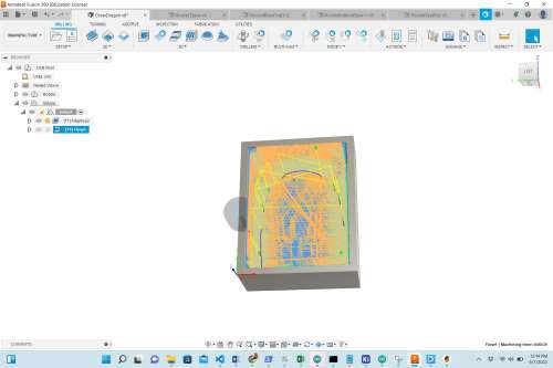
I added a 3D post processing contour finish in the final setup. I selected a 1/8” ball end bit for this, and it smoothed out the corners near the lowest “bed” of the tire. |
 |
This is just a close-up view of the 3D contour finish added in the post processing setup. |
Milling the Mold
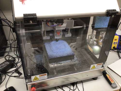
Before beginning to mill my design, I had to generate a piece of machinable milling wax that was big enough to “house” it. I obtained two blocks of machinable milling wax from the Charlotte Latin School Fab Lab, and heated two interior sides with a heat gun until the sides were shiny (starting to melt). When their surfaces were slightly melted, I quickly pushed the two blocks together, and I held them in that position. Colleague and classmate, Nidhie Dhiman was there to lend a hand. As I held the two blocks tightly together, Nidhie worked the heat gun over the adjoining seams.
||
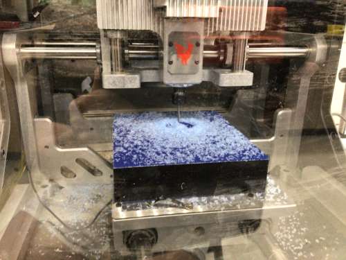
I was now ready to set up my design for milling on the Bantam Desktop CNC Machine in the Charlotte Latin School Fab Lab. I had never used this machine (as it is our latest addition), and I had to heavily rely on the workflow established by colleague, Zack Budzikowski.
Addendum: When I worked on my final project, I wound up molding and casting the crew dragon (Or nosecone) of the rocket. I am adding that portion of my final project below. I milled a wax mold of the crew dragon that has smooth tilted or curved surfaces instead of “steps” towards Z-axis.
Molding and Casting Crew Dragon
At this point, I was ready to prepare my nose cone for milling in our larger, Bantam milling machine at the Charlotte Latin School Fab Lab.
| Image | What Was Done Here |
|---|---|
 |
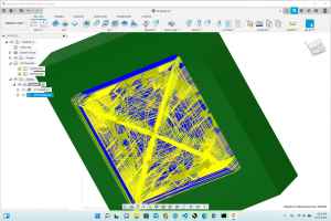
This image shows the start of the adaptive clearing (the rough) pass. |
 |
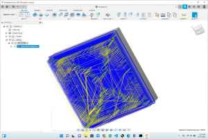
This is the second pass, the “Morph” 3D smoothing pass. For time’s sake, I wound up not carrying out this pass. The job without it was over 4.5 hours long. |
 |
I fused two large blocks of wax together (by using a heat gun to melt them), and I reiforced them with a perimeter of gorilla tape. This image was taken about 10 minutes into the 4.5+ hour job. |
 |
This shows the milling process after about an hour. |
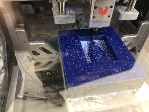 |
Roughly one hour into the job, I paused the milling machine and vaccuumed the pile of wax chips. |
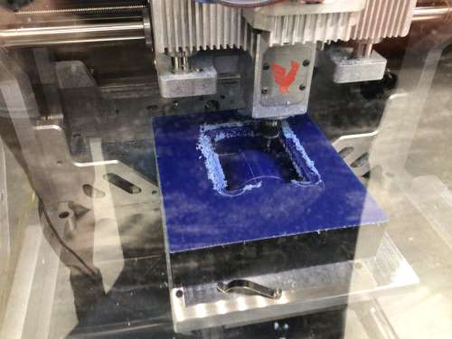 |
After about 3 hours, I paused the milling machine again so that I could vaccuum it again. However, I noticed that the collet was running into the sides of the wax. I decided to continue on with the job at this point though because it appeared as though the areas around the rectangular rim had already been cleared out. When I went to start the job up again, there was a glitch with the computer that would not let me simply press “play”. I had to restart the computer, and the milling machine all over again. Before doing this, I had to manually turn the threaded rod in the machine that was responsible for the Z axis because if the machine re-homed, it would likely run into the wax. (Colleague Zack Budzichowski suggested I do all of this.) Once I had raised the Z axis, I was able to start the job again, but it had to be started from the very beginning. So the part that was already milled out was “air cut” all over again. This was a time delay that was unfortunate. |
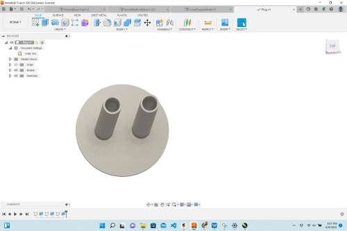 |
Knowing that I was going to have to make a 2-part mold, I designed a “plug” for pouring the final material into the molds (to make a casting). I wound up not using/needing this in the end, but this would actually be utilized in the final day of my project work – INSIDE of the rocket’s base. |
This video shows the milling of the crew dragon mold.
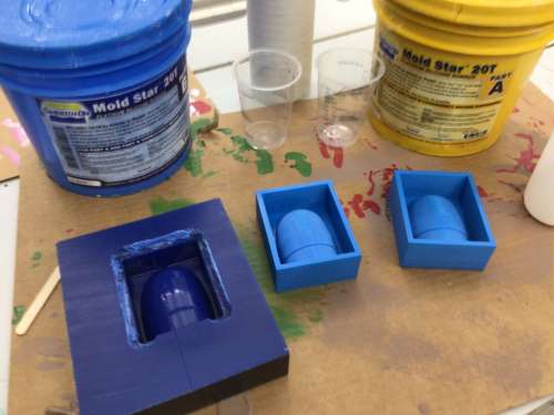
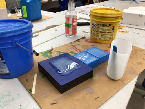
Since I did not do the 3D “Morph” pass, I decided– when the job was done– to again use the heat gun to smooth the surface of the wax. This actually worked beautifully, and I was happy to have made that decision. As a backup, I also decided to 3D print the nose cone (on two different 3D printers in the Charlotte Latin School Fab Lab). When it came time to pour the silicone (for the soft mold), I decided that I would just go ahead and pour it into all three of the molds. I first heavily sprayed each mold with “Smooth-On Universal Mold Release”.
I wound up deciding to just use the two 3D-printed molds (since it would save a little time). The following images show my molding and casting setup.
 |
 |
|---|---|
 |
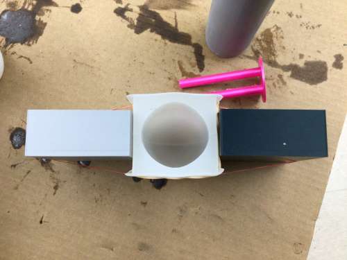 |
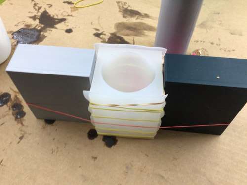
In order to create an optimal shape for the nose cone, I had to stregically use rubber bands. (Classmate Alaric Pan showed me how had used rubber bands with his molding and casting.) I also used two blocks on the end to provide pressure in the middle of the mold. For the silicone, I used Moldstar 20T, and for the hard cast, I used Smoothcast 300.
The following video shows me carrying out the molding and casting process.
The following image shows the molded crew dragon, and how I modified it for attaching the 3D-printed black fins. I used the band saw in the Charlotte Latin School Fab Lab to trim the (gray) rocket body “pipe” I had used when molding it.
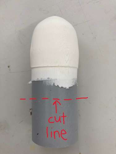
I then used the sanding machine to sand the molded material so that it fit snuggly into the crew dragon fins. Once this was done, I was able to attach it to the rocket’s body.
Bantam Desktop Workflow
Bantam Desktop CNC Milling Machine Workflow (adapted from workflow written by Z. Budzikowski, March 24, 2022 for the Charlotte Latin School Fab Lab).
| Needed Materials/Tools |
|---|
| Bantam Desktop CNC Milling Machine |
| Machinable Milling Wax Block |
| 1/8” Ball Nose End Mill Tool |
| 1/16” Ball Nose End Mill Tool |
| Double Sided Nitto Tape |
| Handling G-Code |
|---|
| 1. After creating the design in Fusion 360, export the file’s G-code for each tool path. |
| 2. Upload both G-code files to the “Engproj” account. |
| 3. Download all G-code files (for each tool path). |
| Software |
|---|
| 1. Open Bantam Software (red rooster icon). |
| 2. Click on “Initial Setup” (in upper left screen). |
| 3. Open the G-code file that was downloaded. |
| 4. Select 1/8” Ball Nose End Mill tool. |
| Material Setup |
|---|
| 1. Obtain callipers and measure wax block and note measurements without Nitto tape. |
| 2. Adhere double-sided Nitto tape on the bottom of the wax block. |
| 3. Remove backing from Nitto tape that was adhered to the wax block. |
| 4. Affix waxy block to milling bed by pressing the wax blank down in the bottom left corner. |
| 5. When prompted, add measurements of wax block and click “Next”. |
| 6. In the “Material Offset” field, there is a 0.001” already populated. This is the thickness of of the NItto Tape (without the paper backing). Leave this value alone. |
| 7. Click Next. |
| Plan Setup |
|---|
| 1. Confirm that the correct file (the one you donwloaded) is indeed in the blue banner at the top of the screen. |
| 2. Verify (or change) the X and Y coordinates based on where the material has been placed in the milling bed. |
| 3. Verify that the Z-axis values are correct; the milling should be shown to begin at the top of the wax block. |
| 4. Click “Next”. |
| Summary Run Job |
|---|
| 1. Ensure the front cover the Bantam Desktop Milling Machine is closed. |
| 2. Review and verify that all of the information perviously entered is correct. |
| 3. Double check that information in the blue banner “Plan Summary” box is accurate. |
| 4. Veryfy “Tool Selection” and “Plan Placement”. |
| Start Milling |
|---|
| 1. Click on “Mill Single File” (if milling one toolpath file at a time), or “Mill All” (if toolpath files are uploaded and intended to be milled at the same time). |
| 2. Run the job; remain at the machine until job is complete. |
| 3. Change the tool (if more than one is used) when prompted. |
| 4. When job is complete, vacuum maching using the shop vacuum. |
| 5. Using “scraper”, remove the wax block material/job from the milling bed. |
| 6. Close front “lid”, and clean area of all tools. |
When milling, you should have at least two tool paths, a roughing pass (adaptive clearing), and a smooth pass (3D finishing). Depenging on how you set up the milling job in your desktop milling machine (for me, this was a Bantam Desktop Milling Machine), these tool paths can either be run together or as separate jobs. If you decide to run these two tool paths as separate jobs, be sure not to remove the material when the adaptive clearing process is complete.
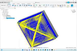
For me, I ran these two processes separately. I used the “Contour” 3D tool path after the adataptive clearning pass as shown in the image below.
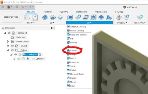
In milling molds (out of any material) it is important to understand how the Z axis is involved in the process. When setting up the manufacturing process in Fusion 360, you will see the word “Steps” many times. The milling machine removes material from the top of the material, and it deepens the steps (in the Z axis) in the roughing passes. In going deeper into the material, all three axes must ne used in circular motions to slowly remove material with each “deepening” step of the Z axis. This leaves round, circular patterns left beingd in the material. The adaptive clearing (rouging) tool path/pass is different from the 3D pass in that the height of steps in the Z axis is drastically decreased. The 3D tool path/pass removes the circular patterns left behind from the adaptive clearing tool path/pass. The 3D tool path is necessary in smoothing the material for molding and casting.
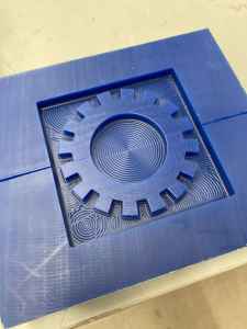
The following image shows the circular patterns after the rough (adaptive clearing) path.
References:
Machining Wax 1 Machining Wax 2 Fab Lab Feed and Speeds Calculator Ben Z. Yuan: Week 8: Molding and Casting
||
Molding and Casting
| Number | Safety Precautions When Working With Molding & Casting Materials |
|---|---|
| 1 | Read the MSDS Sheets for the material you are using/working with to enure you follow proper safety– ie) storage, ventialtion, safety gear. |
| 2 | Put on rubber gloves and safety goggles. Wear apron to protect clothing if desired. |
| 3 | Mix Part A and Part B according to instructions on labels on container. Make note of mixing ratios, for example, 1 Part A: 1 Part B. |
| 4 | Using accurate measuring containers, (I suggest using Multipurpose Disposable Plastic Measuring Cups - Baking, Cooking, Epoxy Resin, Mixing & Measuring Cups)measure specified amounts of each part of the molding material. I found that adding slightly more of Part B provides better hardening results. |
| 5 | Determine (from material label) the “pot time” of the material with which you are working. Using a sturdy spoon or wooden popsicle stick, mix the molding materials for just under the specified time. |
| 6 | Determine (from material label) the “cure time” of the material with which you are working. |
| 7 | Pour material into prepared molds. |
| 8 | Using fists, pound on surface on which the materials are resting for about five minutes to cause bubbles to rise to surface as much as possible. |
| 9 | After cure time is up, and wearing rubber gloves and safety goggles, remove the material from the mold(s). |
| 10 | Repeat steps 1-9 for the second stage of molding and casting. |
||
| |
| |
|
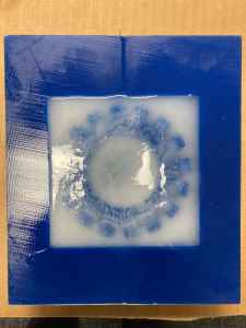
After allowing the Dragon Skin NV (Platinum Cure Silicone Rubber) to cure for nearly 17 hours, it still did not set. The video below shows me removing the dragon skin material from the milled awax.
||
As I dug deeper into the milled wax, the Dragon Skin was much harder. I wondered if I had let it sit longer if it would have solidified completely.
Knowing that the harder plastic worked well (when we tested the materials as a group), I decided to mix Smooth Cast 3000 (Bright White Liquid Plastic) and pour it into the milled wax.
||
With fellow classmate–Andrew Jiang– I mixed and poured Mold Star 20T (Platinum Silicone Rubber) into my mold. During our group work, we did not realize that we had Dragon Skin NV (Platinum Cure Silicone Ribber); I thought is would be good to make a second prototype of silicone for comparison.
||
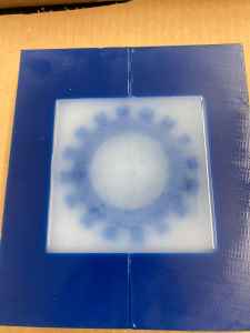
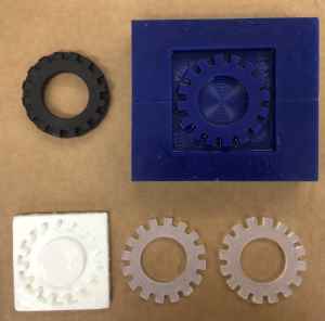
The following images show the progression of my tires.
| From Left to Right In Sequence | Molded and Casted Tire Comparison |
|---|---|
 |
 |
This week, I found this–“falcon_users_guide_042020.pdf”– which seems to have a lot of useful information in it about the Falcon 9 and Falcon Heavy rockets. For my final project, I will likely make a 2-part mold to make the tires for the SpaceX Transporter Erector Launcher. The following images show information about the Falcon 9 and Falcon Heavy rockets and the SpaceX Transporter Erector Launcher.
For our group assignment this week, we were asked to review the safety data sheets for each of the molding and casting materials in our Fab Lab. We then were asked to prepare and compare test casts with each of them. We worked as a group together on March 24 until we got the project completed. With Avery Horvath, I helped mix all of the products and helped to make observations of the molds. We divided up the product MSDS’s. To see our work, please visit our site. To see what I did on this work, please visit this site.
Links to Files: DataSheets Fusion360 File OBJs STLs