3.0 Computer-Controlled Cutting
Vinyl Cutting
This week, Dr. Gershenfeld stated that the vinyl cutter is the most under-used machine in the Fab Lab, and the laser cutter is the most over-used machine in the Fab Lab. On Wednesday afternoon, our group (five of us) sat down to meet. We all began making our stickers.
In the Charlotte Latin School Fab Lab, it is trafition to make a sticker and place it on the window of Mr. Dubick and Dr. Taylor’s office. I had actually designed my sticker last week, but the only documentation I had of it was the final result (shown in Screenshot 1 below).
For this week’s vinyl cutting assignment, I wanted to make a sticker that is related to my final project. The first thing I did was an Internet search for a SpaceX logo. There were a lot of images to choose from, but I chose this one because it looked as though it was a silhouette with no background. I copied the image, opened Silhouette Studio (the software for our vinyl cutters), and placed the copied image onto the work “surface”. From the right-hand tool options (Screenshot 2), I selected the “trace” tool. I then had to “Select Trace Area”, and I highlighted the logo only, and Silhouette Studio then traced the logo/made a bitmap of it.
![]()
Once the SpaceX logo had been traced, I noticed that the silver “slash” through the “X” at the end was not being picked up by Silhouette Studio’s tracing feature (seen in Screenshot 3). I began to modify the parameters (increasing the threshold) of the newly created bitmap in an attempt to get the “X” traced, but it did not work. The only way to get the “X” to appear was to increase the threshold to the point that everything else was not legible (Screenshot 4). I decided that in order to get the silver slash through the “X”, that I would cut this illegible version and discard everything else.
Screenshots 5 and 6 show the finalized bitmaps of my SpaceX logo. I searched through our vinyl scraps box in the CLS Fab Lab, and I was thrilled when I found a blue that resembled the SpaceX blue. I also pulled out a silver piece to cut for the slash through the “X”. I placed the blue scrap on the tacky cut mat, and loaded the “paper” in the vinyl cutter. To cut it, I clicked on “Send” from Silhouette Software on the computer. I repeated this with the silver scrap piece of vinyl material. Screenshots 7 and 8 show the blue and silver vinyl pieces mounted on the tacky cut mat as they were loaded into the vinyl cutter and about to be cut.
![]()
As I was searching for my SpaceX logo earlier, I came across this unoffical SpaceX logo, called SpaceX Starman. I wondered if I could get this logo to work in a vinyl cutting. Now that I had cut the blue and silver SpaceX logo, I wanted to try the SpaceX Starman, but this one contained three colors (black, gray and white)/three layers in the end. I repeated the same process to make a vinyl-cut sticker. (Screenshot 9 shows the bitmap trace of the SapceX Starman logo). I once again rummaged through the scrap box and thankfully found all three.
Colleague (and Fab Academy student), Nidhie Dhiman, showed me some new vinyl options that had recently been purchased. I found a piece of sparkly black, and I decided I wanted to try to use that for my black background as it would have a starlit appearance. In handling this sparkly balck vinyl (Screenshot 10 below), I could tell that it was much thinner than the vinyl I had always used. I ran the cut using the vinyl cutter, and as predicted (warned by Nidhie Dhiman), the cut came out poor (Screenshot 11). I seached for black vinyl in the scrap box, found a perfect piece, and re-cut the SpaceX Starman logo on shiny black vinyl. Screenshot 12 shows all five of my vinyl-cut stickers together along with the transfer paper that I would now need for combining all of my layers in each design and transferring the logos onto a final surface. The black, silver and white would be used together (in layers) to create the SpaceX Starman sticker. Silver would be the lowest layer with white and black on top of it.
![]()
In creating the two logos, I needed to use fine-tipped tweezers and a scalpel to separate the other colors (blue/silver and gray/balck/white respectively). I found this to be the most-challenging part of my logo design. As I got deeper into the separation of vinyl from the paper backing, I began to notice that the blade on the vinyl cutter was dull and needed changing. The image below shows my final vinyl-cut logos on the outside case of my laptop. Some of the rough edges of the SpaceX Starman show the effect of the dull blade.

This weekend, I did more Internet searching for logos, and I found this Falcon 9 SpaceX logo, and I think I will include this in my final design. I feel that my grandson will think this logo is cool. Another cool option that I think my grandson would like is this logo for the Crew Dragon. The amount of available space on my molded rockets will determine which one I wind up using. I also feel that I could put the Falcon 9 logo anywhere on the outer electrical housing of my project.
Parametric Designing
I have come to realize that parametric designing cannot be done in 2D design softwares (like Inkscape and Corel Draw) by simply using object clones. So this week, I began to look closer at 2D designing in Fusion 360 (as I still cannot access SolidWorks). Sadly, I also realized that the previously designed box for the electrical housing of my final project also needs to be re-designed because I utilized tabs in it. Tabs are not “felxible” enough to utilize with more dense materials (like 1/8” acrylic or plywood) that I had planned to use.
After the class with Dr. Gershenfeld on Wednesday, I knew that I still had work to do in learning how to make parametric designs work. The first thing I did was watch this tutorial, Creating Parametric Designs in Fusion 360. What I didn’t realize was that a parameter can be set after making a design; originally, I thought that the parameter would have to be identified at the start of designing a project. After watching this tutorial, I decided to test out a parametric value in Fusion 360.
During our evening of group work (Wednesday), I did a lot of research in trying to determine the necessary export files from SolidWorks and Fusion 360. (This research is documented on my Week 3.5 Group Assignment Page). With this research, I learned something critical from this site; I found that if a design is made in Fusion 360, it can be exported as a .dxf file. This file can then be opened in Corel Draw, and it can be further lasercut using the appropriate settings. So I set off to re-design my Bucky Ball– this time in Fusion 360.
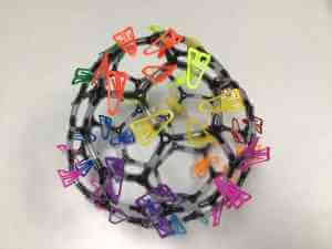
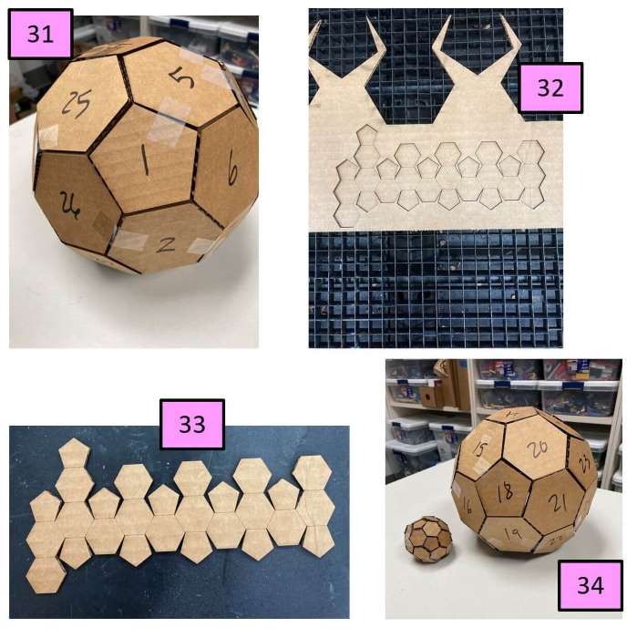
On the drive to work on Thursday, my husband infomed me that upper school chemistry teacher, Mrs. Jessie Selner, had a model of a Bucky Ball. I decided to visit her and see if I could borrow it. When I designed the Bucky Ball in Corel Draw, I was making that drawing on a false assumption– that there were only two pentagons on the poles with hexagons filling in the rest of the sphere. I obtained and examined the Bucky Ball model from Jessie Selner, and I realized there were many pentagons– more than just two at the poles. So I decided to mark all of the pentagons with colored plastic paperclips to determine the actual arrangement. The image below shows what the model Bucky Ball looked like when I had completed this task.
After examining the Bucky Ball Model, I saw that the pentagons sometimes were actually placed next to another pentagon, and there was seemingly no “rhyme or reason” as to the arrangement. So I resorted to an Internet search about the molecular arrangement of the 5-C and 6-C sugars in a Bucky Ball. Site 1 and Site 2 provided some interesting information:
Information Found and how this Affects My Design of a Bucky Ball
-A bucky ball contains 60 carbon atoms. This means that there are 60 carbon atoms with 3 bonds each. This totals 180 potential joints that will need to be addressed.
-Full name is “buckminsterfullerene”. This has no relevance to my design.
-Bond angles are 120 degrees. Any joint angles would have to be 120 degrees in design.
I started to think about how I would address and connect the joints in my laser-cut Bucky Ball. After a discussion with Tom Dubick about this, he led me to a software (called Cuttle), looked interesting in that it might be able to help me address the 3D nature of my Bucky Ball. In fact, when I went to this site (which turned out to be full of parametrically created kits), it had a sphereical 3D design–similar to mine– on it. In looking at the design on this page, I noticed how each side of the sphere were connected, and I decided to create a “connector piece” similar to the one on the Cuttle page. Upon first glance, I thought I could simply make a 120-degree joint. So I designed the one shown in Screenshot 13 (below) in Fusion 360; it is merely two straight pieces with a 120-degree joint between them. I also tested this file out with Corel Draw by exporting it as a .dxf, opening it and modifying it in Corel Draw. It worked.

At this point, I wanted to start designing the 5-C and 6-C sugars in Fusion 360 because I needed to see how I would use the connector. Before making the design though, I decided to click on the picture from the Cuttle website that looked similar to my sphere. Low and behold, it was actually Nadia Bremer’s Fab Academy assignment from a previous year; it was called “Parametric Press-Fit Construction Kit. I did not want to actaully read her project page because I didn’t want to obtain any designs from her. From what I could tell, her spheres had fewer faces than my Bucky Ball. I did look again at her connectors, and I realized that my simply-designed 120-degree connector piece would not likely work. It needs something to “latch onto”.
I decided to go back to design my pentagon and hexagon snowflakes again– this time in Fusion 360, and I wanted to be able to change their parameters properaly. First I created a pentagon, and I right-clicked on it and selected “Repeat Edge Polygon” (as shown in Screenshot 14 above). I was quickly able to design the 30-pentagon-shaped snowflake, and the 18-hexagon-shaped snowflake (in Screenshots 15 and 16 above).
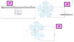
It was now time for me to test out my parameter. I created a “Side Length” parameter (shown in Screenshot 17). I deployed the parameter (in Screenshot 18), but I realized that what I thought was the length was actually the height of the slanted side (Screenshot 19). Knowing that the functionality of the parametric setting actually worked, I “undid” this action and sent the .dxf file to Corel Draw to add “notches” in the sides of each snowflake.
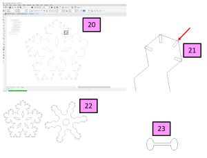
I eye-balled the placement of the notches (as shown in Screenshot 20) in Corel Draw. I used the “Virtual Segment Delete” button to remove the overlapping areas from the notches in the snowflake edges. The final snowflakes are shown in Screenshot 21. Screenshot 22 shows the overall result of deleting all of the overlapping portions in Corel Draw. Knowing that the cardboard I was using was going to be flexible, I thought I could design something differently to hold the snowflakes together in the newly created slots. I quickly skecthed a dumbbell shape (Screenshot 23)in Corel Draw and decided to laser cut these as well in the laser cutter.
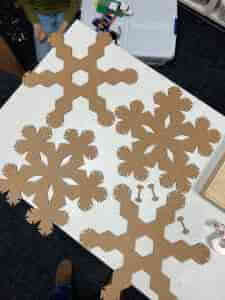
This image shows the giant hexagon and pentagon snowflakes after they were laser cut (along with three of the “dumbbell” connector pieces). The dumbbell connectors did not work well at all, and I needed to think of a new design.
In order to try to remedy how the connector pieces would work, I had to bring the two snowflakes together in Fusion 360. I struggled greatly with how to do this precisely/accurately in Fusion 360, and I eventually looked to the Internet for help. I found this site, and after attempting to do this for about 30 minutes, I realized my snowflake designs were too dissimilar to get the sides to line up properly. Instead, I descided to design the Bucky Ball using regular pentagons and hexagons in Fusion 360.
Once again, to test parametric functioning, I made a pentagon (with a base length of 0.6”). I deployed a “Side Length” parameter of 0.5”, and this was successful in changing the dimensions of all sides of the pentagon. (Screenshot 26 shows this test). Since I now wanted to just use pentagons and hexagons in making the Bucky Ball, I looked up to see if I could find out the arrangement as if it were cut open and flattened. I found this site and learned that its name is a “truncated icosahedron”. So I set off to design this in Fusion 360.
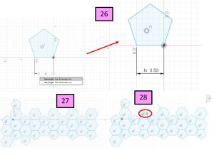
At this point, I was well-versed in how to make and manipulate the polygons. I was quickly able to create the truncated icosahedron shape (seen in Screenshot 27), and I tested out the “side length” parameter (making it 2”). It worked near perfectly (Screenshot 28); there was one errant line that I accidentally created at some point.
Once this was created, I decided to scale the whole model in Corel Draw to fit onto a piece of cardboard that we have plenty of in the Fab Lab (dimensions of 27” x 16”). I made all of the lines hairline (0.001” thickness). However, there were lines in the document that I wanted to be scored (rather than cut). So I made these lines red in color (R: 255, B: 0, G: 0), and I moved them to a new layer of their own in the Corel Draw Object Managers window. (Screenshots 29-30 show the design in Corel Draw with the red score lines created and the new layer created in the Objects Manager window).

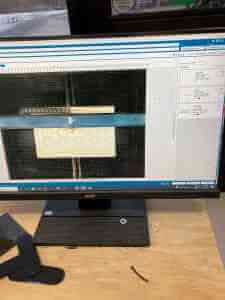
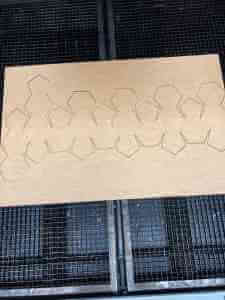
The images below show the file loaded into the laser cutting software on the Fusion Pro in the CLS Fab Lab and the resulting job after it was completely cut (all in one piece).
The images below show two Bucky Balls with different dimensions (from changing the parameters in Fusion 360). In Screenshot 31, the side dimensions are 2”. Screenshots 32 and 33 show the truncated Bucky Ball with 0.2” dimensions, and Screenshot 34 shows the assembled Bucky Balls with 2” and 0.2” joint lengths.
Since the kerf on the Fusion Pro Laser Cutter that I was using was 0.14”, this could really add up if each pentagon and hexagon were cut out all of the way. However, at least one side of each of the 11 pentagons was scored and not cut, and this helped to reduce the kerf that added up with them. Four of the hexagons also had only one side that was scored, and the kerf that resulted from 5 sides of these hexagons (rather than 4 cut sides of the pentagons) would have closely been equal. Obviously those shapes had more surrounding “gaps”. Since I had taped the first versions of the bucky ball (parametrically, in three different sizes by the time I was finished), I was able to bring the edges closer together with the tape. Bringing the sides together without tape definitely had advantages. I would find (much later) that it was the kerf that was making the Bucky Ball difficult to put together with connectors.
So far, the two Bucky Balls that I actually cut were held together with tape, and I needed to make the joints press-fit. The first time I tried the press-fit pieces (with the giant snowflakes and dumbbell-shaped pieces), it did not work. I thought about what the junctions and connector pieces needed. The junctions on the truncated icosahedron (giant piece of all of the pentagons and hexagons) needed a “slot” wide enough for the connector to fit into, and the connect pieces needed a way to account for the bond angles (120 degrees) between each of the 5-C and 6-C sugars (pentagons and hexagons respectively). I decided that it would be easiest to add the holes to the sides of each free-sided pentagon and hexagon in Corel Draw. Before I added the “slots” where the connector pieces would go, I decided to count how many slots I would need for the whole truncated icosahedron. I placed a piece of clear celophane over a computer screen with the truncated icosahedron outline on it and marked the location of each slot (as shown in Screenshot 35 below). After counting 101 junction areas on the giant piece, I now wanted to design how big the slots would be and where they could be positioned in the design. I used a white board to map out my thoughts and do a little trig to determine how far away each slot needed to be in order to be in contact with the slot on the oposing side when it was folded. I had a collaborative session with colleague (and mechanical engineer, Zack Budzichowski), and I showed him my plan for what I called a “claw-like” connector (shown in Screenshot 36 below). Zack suggested I could also try adding a living hinge to the connector pieces to allow for built-in tolerances.

Both connector pieces would require a small square “slot” in the parent piece that was sqaure in shape and 0.15” x 0.15” dimensiins. I added all 101 of them to the file in Corel Draw; this was very time-consuming because I had to properlay space them roughly 0.3” away from the edge of the pentagon and hexagon, and they had to be at the proper angle and centered in the middle of the side. After placing all of the slots on the document, I then designed the living-hinge connector piece. This was a simple design in Corel Draw, and I was able to copy and paste it to reach the 101 needed pieces. I once-again made the lines that would be scored red in color (to separate the laser cutter settings for scoring and cutting). Screenshot 37 above shows this, and Screenshot 38 shows the truncated icosahedron with “slots” being laser cut.
Once I had the one-piece icosahedron cut, it was now time to laser cut the living hinges. This is where my project got derailed. While the truncated iscahedron was cutting, I observed that the small (0.15” x 0.15”) slots had– what I call– “double ups”, where there were multiple layers from copying and pasting the designed slots in Fusion 360. Another faulty design aspect of the slots was identified as construction lines (in the form of “X’s” in the small slot squares) from Fusion 360 into the slots to Corel Draw. Both of these issues caused the laser cutter to pass repeatedly over the very small area outline of the slot-squares. The cardboard was starting to burn in a few of the slots, and I decided to stop the job. I went back to the file in Corel Draw and removed the double ups and the construction lines in all of the 101 square slots. The second laser cutting of the truncated icosahedron was considerable faster once these were removed. Now I had to move on to cutting the connector pieces.
The connector pieces were very small in size, and the living hinges (three living hinges on each connector piece– one in the middle and one on each end). The lines that made up the living hinges were also extrememly close together on the connectors that only had a 0.15” width. In addition, I had 120 living hinges spaced very close to each other on the Corel Draw file. When I went to cut them (on the Fusion Pro in the CLS Fab Lab), there was so much power in such a concentrated and confined area on the cardboard, that a fire quickly arose. I immediately stopped the job and reset the laser housing to its home position in order to remove the burning cardboard. When the fire was extinguised, the burn area was about 4” in diameter. Feeling quite defeated at this point, I went to speak with Tom Dubick.
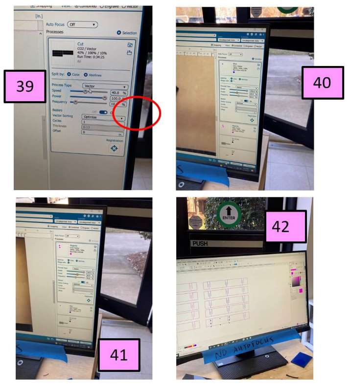
Tom made several suggestions about what I could do at this point, and he stopped what he was doing to show me. We went back to the Fusion Pro, and Tom showed me how to increase the speed (to 80%) to prevent the laser from focusing on one area for too long. (Screenshot 39 shows where we changed this setting on the Fusion Pro). We tested cutting the connector pieces again, and the living hinges were again starting to burn. Tom Dubick then suggested that we increase the speed again to 100% and decrease the power. This worked better, but the living hinges were getting completely cut off due to the low density and composition of the corrugated cardboad. For the next test, Tom Dubick suggested that we make two sets of connectors different colors and use color mapping when we select the settings. Screenshots 40-43 show that we kept the speed increased and reduced the power even more in each test. We were eventually able to successfully cut the connector pieces without burning them.
When I tested the newly (and successfully) cut connector pieces, they did not work at all. As I bent them, they crubled and fell apart due to the minimal amount of material in corrugated cardboard. (Seen in Screenshots 43 and 44 below). I was able to quickly design my second connector idea (shown in Screenshot 45 below). I cut one of these connectors and tested it, and IT WORKED! I duplicated this one into a document containing 120 of the connectors and cut those. I was then able to assemble the final, press-fit Bucky Ball. (See all three Bucky Balls in Screenshot 46 below).

This is how it looked in the end, as I finished putting it together as a FULL PRESS-FIT BUCKY BALL!
