11.0- 12.0 Group Project Week– Mechanical Machine Design
This is Mechanical Machine Design week. Way back, at the start of “Electrical Design” week, Charlie Horvath and I were cutting PCB’s for our group late at night. As we searched that evening for desktop milling machine bits, we were somewhat frustrated by the fact that it was difficult to locate the correct bits (many of them had been “filed”/put away incorrectly). We talked about how cool it would be to make some sort of machine that could easily locate materials in the Charlotte Latin School Fab Lab. We posed this idea to the group, and they took our thoughts to a new level.
I wound up desgining the bit box bases and the bit box caps. I also drew the “schematic”/drawling of the electrical components (after Avery had finalized them). Nidhie Dhiman and I got the NEMA17 motor working and designed the iPAD case and the front door of the “Wheel-O-Bit”.
Getting NEMA17 Stepper Motor Working with L298N Motor Driver
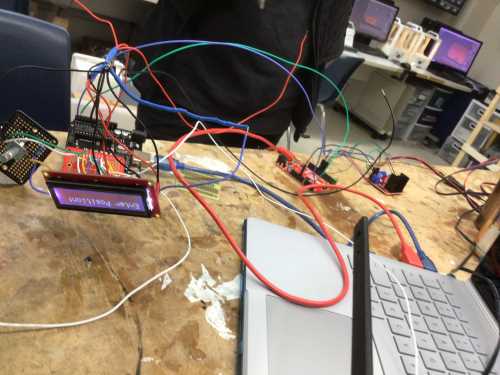
On April 6, colleague/classmate, Nidhie Dhiman and I started to work together trying to get one NEMA17 Stepper Motor functioning properly. As Nidhie Dhiman and I worked to get one NEMA17 Stepper Motor working, we used the same 12V power supply with an L298N Motor Driver attached to the NEMA17 Stepper Motor. Since I had not used theL298N Motor Driver with a NEMA17 Stepper Motor, I researched and relied heavily upon a few wesbites.
The first website I used – called ““SKR Pro V1.1 - TMC2208 UART v3.0 (BigTreeTech)” was useful in understanding the rationale behind the wiring we would use for the NEMA17 Stepper Motor. However, this wound up not be an ideal site in the end because a CNC Shield was not utilized.
I then searched again and found this site– “MC2209 and TMC 5160: Guide for MKS Gen L and SKR V1.3”; this too wound up not being great because he was really only comparing the different motor drivers that could be used in conjunction with NEMA17 Stepper Motors that were being replaced on a 3D printer. It was after this video that I began to find more useful information.
This site showed me we needed a GRBL file when using NEMA17 stepper motors. I followed this link, and I was eventually sent to this github site that contained the source code for the .h files and an extensive collection of C files. In addition to this, I found a “GCode Sender” site that would be useful for mhy final project in developing GCode for coordinates in my SpaceX Launch Alert System. This site may also be fruitful in developing coordinates for our “Milling Bits Storage Concept”.
“This final site” that I found was incredibly helpful in how to wire the NEMA17 Stepper Motor to the L298N Motor Driver. Although this viewo showed how to connect two small DC motors to the L298N Motor Driver, Nidhie Dhiman and I were able to logic our way through the connection of just one NEMA17 Stepper Motor. This site actually showed a diagram of how the NEMA17 Stepper Motor should be connected. After wiring it, we eventally got the NEMA17 Stepper Motor to respond (similarly to how my NEMA17 Stepper Motor had responded with the CNC Shield a few days ago). The motor would vibrate for a short period (the central axis spattering back and forth in a “confused” motion), and then eventually “die out”, stopping the vibration altogether.
After several attempts to remedy this, we realized that the motor responded better when Nidhie Dhiman held her fingers under the IN1, IN2, IN3, and IN4. She seemingly was completing the circuit whenever she touched the ends of the IN1 and IN4 pins with a forefinger on each hand. It dawned on me that she was literally conducting the current through her fingers, and I remembered that we had removed the lateral headers on each side of the EN1 and EN4 pins. We quickly found the headers and repositioned them back onto the L298N Motor Driver to the left of the IN1 pin (the ENA pin) and to the right of the IN4 pin (the ENB pin).
After this, we plugged it all in again with the 12V power supply, and the motor continued to “die out”. We had a conversation with Dr. Adam Harris, and as we examined the power supply, Dr. Harris realized we had an AC 12V power supply and we were trying to use with a DC motor. Ugh! Feeling incredibly dumb, Nidhie Dhiman searched the drawer full of 12V power supplies, and she was able to find only one that was a DC 12V power supply. We plugged this in, and the NEMA17 Stepper Motor then began fucntioning beautifully as “commanded” in the Stepper One Revolution Arduino file (attached below). The follwing video shows our work and FINAL SUCCESS of getting a NEMA 17 Stepper Motor to function properly with a L298N Motor Driver.
||
Designing and Printing Bit Box Base and Bit Box Cap
The following table shows the steps (and description) of how I designed the bit box base and bit box cap in Fusion 360.
| Photo | Description |
|---|---|
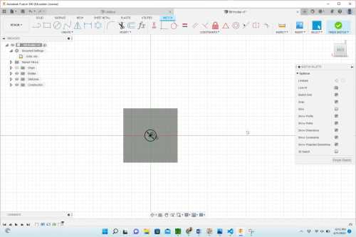
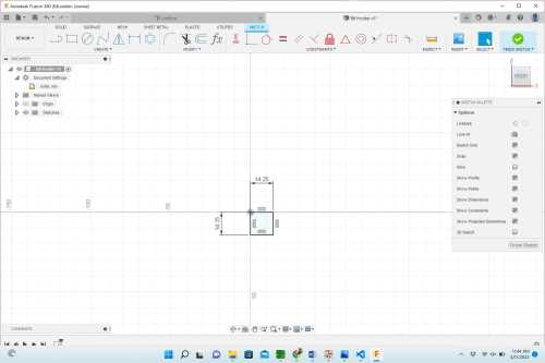 |
Make a square with dimensions of 14.25mm x 14.25mm. |
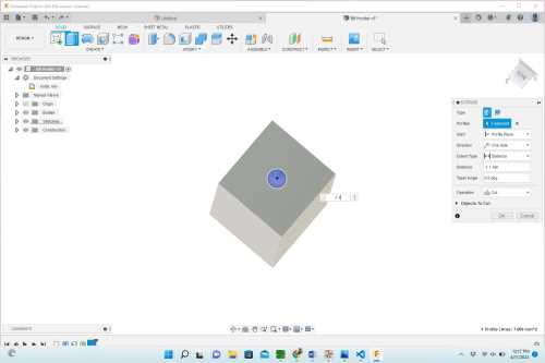
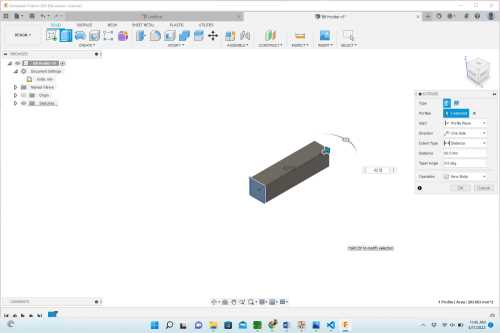 |
Extrude 62.5mm from the front to the back. |
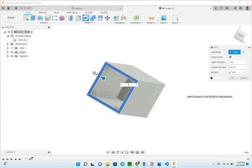 |
Make the new 3D feature a shell (with a 1 mm shell diameter). |
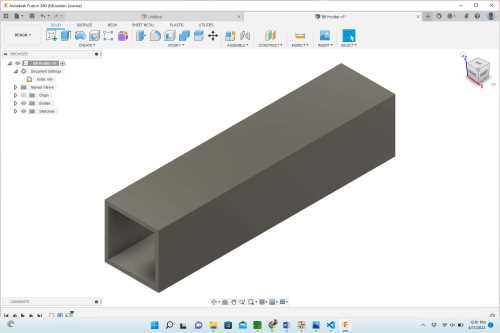 |
This is what the bit holder looked like after it was shelled. |
 |
Add an offset plane to the bottom of the bit container. Make a (center) circle with a diameter of 3 mm. |
 |
Make the center circle a “hole”. This then completes the design for the bottom of the bit box/container. |
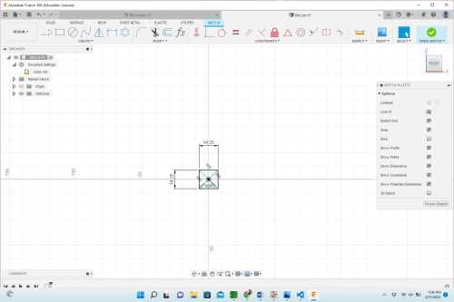 |
To begin making the bit lid, start by making another square with the dimensions of 14.25mm x 14.25mm. |
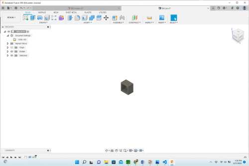 |
Extrude the base rectangle 10mm from front to back. Make the new 3D cube a shell with a diameter of 1mm. |
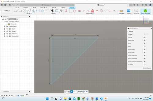 |
Create an offset plane on the bottom of the cap. Determine the points needed to form an isosceles right triangle by measuring out lines that are 2.75mm in length from each side of the right angle. |
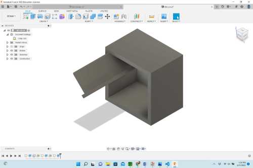 |
Using the pre-determined points, make a “T-shape” on the bottom (offset) plane. Extrude this “T-shape” 20mm. |
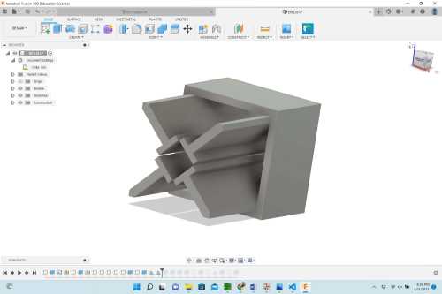 |
Repeat the last two steps for each of the for corners. (Or, select all of the faces of the extruded “T-shape” and select “Mirror” using both the X and Y axes until all four corners contain the “T-shape”.) |
 |
The original four “T-shapes” in each right angle needed to be re-designed because the opening in the middle was too large–preventing them from gripping and holding tightly onto the bit. This shows the new “curved” design of the “T-shapes” in the right angles. |
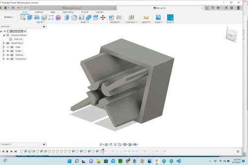 |
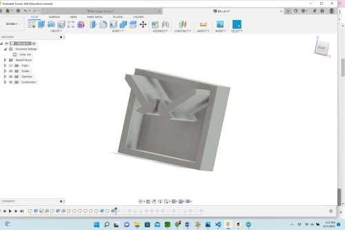
This shows the final cap design with bit grips working well. |
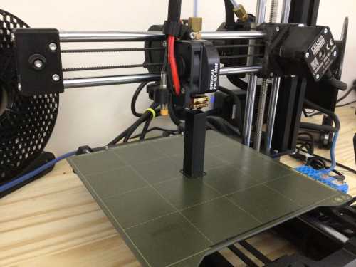
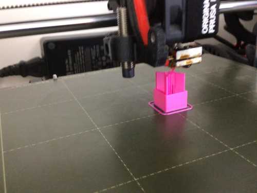
The following images show the final designs as they were and after they had been 3D printed using Prusa printers in the Charlotte Latin School Fab Lab.
 |
 |
|---|---|
After the base and the cap were done being 3D printed, they were joined together. However the cap was very loose, and the original cap could not hold onto a bit.
 |
 |
 |
|---|---|---|
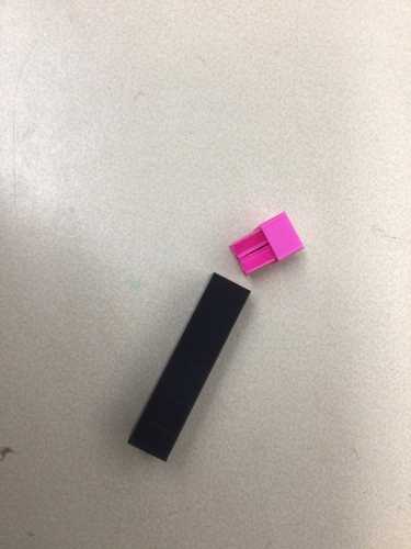
| This shows the two pieces (bit box/container)– base and cap together after 3D printed. | This shows the first designed cap placed on top of the bit box/container base. | This shows the assembled bit box/container base and cap placed in one of the bit trays. |
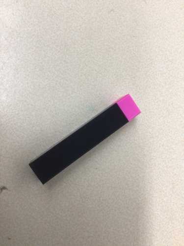
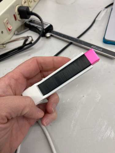
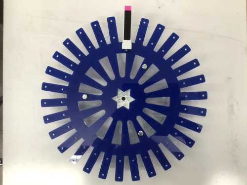
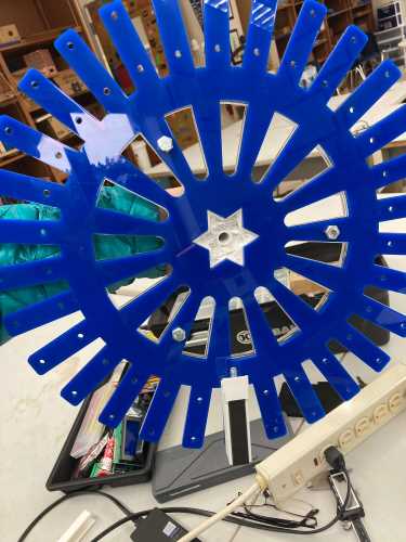
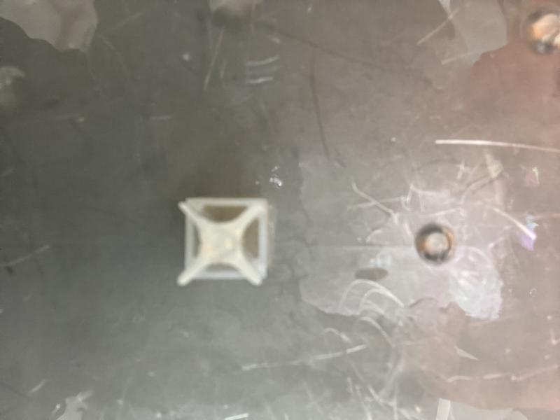
The bit box/container base fit perfectly into the bit tray (as seen in the image below on the left). However, when the cap is placed on the base, and the two pieces are turned upside down, the cap falls off (shown in the image on the right). The bit box/container cap was then redesigned (as mentioned above). The following two images show the bit box/container base and cap as they were placed into the wheel.
 |
 |
|---|---|
Once the cap was re-designed (image below on the left), and 3D printed again, we took a desktop milling bit and placed it in it (image below on the right). The bit was held snuggly, but after a few times of testing the cap with the bit, one of the internal “T-shapes” broke.
 |
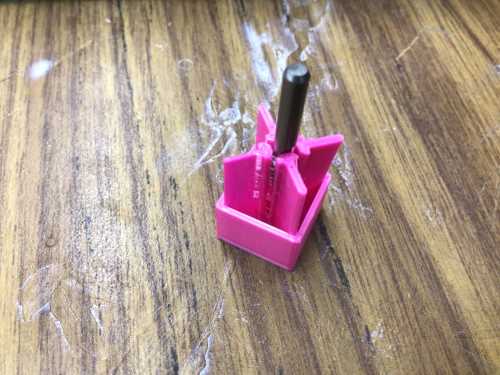 |
|---|---|
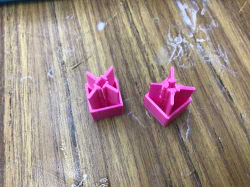
The following two images show the newly assembled bit box/container that wound up being much better than tthe first. When the bit is held by the four curved “T-shapes”, it causes the sides to push out slightly. This puts pressure on the inside of the bit box/container, and the cap stays on. However, when we handled both verion 1 and version 2 of the bit box/container cap, both of them broke. We decided to try printing them in the Formlabs (Prusa) Resin 3D printer in the Charlotte Latin School Fab Lab. The following images show us using the resin 3D printer.
 |
 |
|---|---|
| Bit Box Cap After Resin Printing (Nidhie Dhiman with me) | Top Version of Bit Box Cap After Resin Printing (Nidhie Dhiman with me) |
We tested the one bit box cap, and it fit perfectly into the bit box base. When we added an actual bit, it too worked better than expected.
Nidhie Dhiman set up the remaining bit box caps for resin printing (30 of them), and the following video shows me finishing them. (I took them out of the Resin 3D printer– which took over 12 hours– and I put them in the resin wash and final curing box). As I did this, one of my former student D.S. came to “help” and see what they looked like.
||
Designing and Laser Cutting iPAD Case
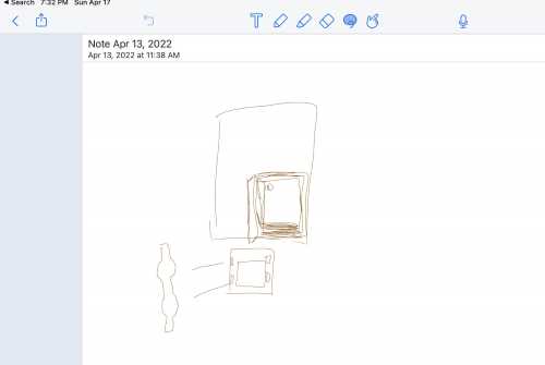
For our Universal Bit Holder/Organizer, Nidhie Dhiman and I sat together and designed the iPAD case that would be placed into the front “door”/face of the entire device. Since Nidhie Dhiman had created the checkout system using Reftab software, we needed to make sure that the iPAD would be mounted at an optimal height. The camera on the iPAD needs to be able to scan a bar code on the sides of the bit box bases, and we had to make precise measurements. As Nhidie made and called out measurements, we drew out a rough sketch of the iPAD holder in the Notability app on my iPAD (shown below), and we used Corel Draw to design it.
The following table shows how Nidhie and I collaborated together to design the iPAD case.
| Image | Description |
|---|---|
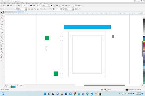 |
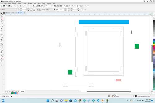
The iPAD used was a 7th generation iPAD with dimensions of 9.8” × 6.8” × 0.29”. A box was drawn with dimensions of 8” x 11.5”, and a second box with dimesions of 6.25” x 8.25” was placed in the exact center of the larger box. The two boxes created a “frame” that would serve as the outer covering of the iPAD “case”. We decided to use slot-fit sides, and to place the vertical slots exactly 1” from each corner, we used a 1” x 1” colored box as a spacer for slots that were 1.185” x 0.25”. (We planned to use clear acrylic that was 0.23” thick). Once the slots were placed, one vertical side piece was created so that it had rounded “tabs” that would fit into the previously created verticla slots. The rounded tabs were created by making an oval with the same (long) diameter as the height of the slots, and this oval was placed on the outer edge of a 0.6” x 10” rectangle. The segment delete tool in Corel Draw was used to remove the overlapping lines. A small (gray) spacer was created to make sure each verticla slot was the exact same distance from the outer edge, and a turquoise long spacer was created to make sure they were consistently parallel to each other. |
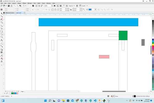 |
Similarly to how the vertical slots were created, the 1” x 1” green “spacer” box was used to place the horizontal slots. We now used a pink “spacer” box to ensure the horizontal slots were the same distance from the inner part of the front “frame”. |
 |
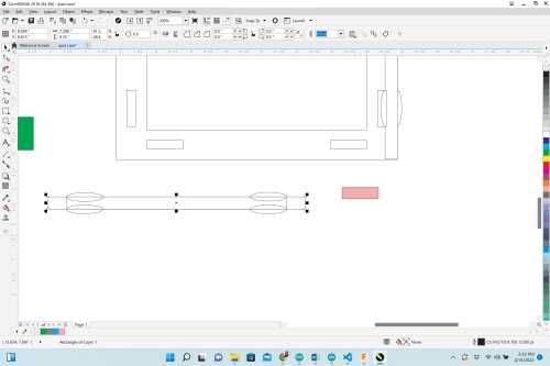
To make a horizontal side piece, a 6.26” x 0.839” rectangle was placed on the bottom horizontal portion of the “frame”. The two slots were copied and pasted and the same pink spacer was again used to ensure they were equidistant from the bottom line. |
 |
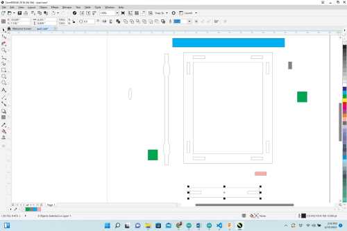
Ovals with the same long length as the slots were again placed on the outer part of the horizontal piece rectangle, and the segment delete tool was used to remove the overlapping areas. The copied and pasted rectangular slots were also deleted.each side piece was duplicated, and all lines were made hairline for laser cutting. It was at this point that we performed a test cut of the iPAD case on coardboard, and we realized that the bottom side pieces were too short. |
 |
This shows how we modified the bottom side pieces to make them the correct length so they would come into contact with the vertical side pieces. |
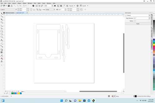 |
This shows the final design of the iPAD case. After laser cutting it a second time on cardboard, we realized that we neglected to do two things: 1) We forgot to allow access to the power button on the bottom of the iPAD’s front screen; and 2) we realized tha the iPAD was sitting slightly too low inside the case. We decided to add a 2” circle to th center of the inside bottom (the inner horizontal line) and use the segment delete tool to remove the overlap. To remedy the low-position of the iPAD, we used the cutout pieces from the slots to “lift” the iPAD inside the case 0.24”. Coincidentally, this also provided space for the iPAD’s charge cord which we also had not accounted for. Finally, we removed the top horizontal slots because this would allow curators to remove the iPAD easily by sliding it upward. |
| As we performed this test cut, we realized that there were lines that had been “doubled up” in Corel Draw. This caused the laser cutter to make two passes over the same lines, and this can sometimes result in the cardboard catching on fire. Thankfully, this did not happen. We were able to remove the doubled-up lines when we modified the design in Corel Draw. |
Designing and Laser cutting Front Door
Once again, Nidhie Dhiman and I worked together to design the front door of our Wheel-O-Bits, and this piece was also intended to be cut out of clear acrylic with a 0.23” thickness. The iPAD cases needed to be positioned and adhered to the front face so that the iPAD camera would line up with the barcodes on the bit base bases. In order for curators of the Wheel-O-Bits to be able to access and re-stock the bits, we needed to place hinges on the front. We found three hinges in the Charlotte Latin Schoo Fab Lab and used callipers to measure their outer dimensions and screw holes. We also decided to place the hinges on the right side of the box to allow more support for the weight of the iPAD and its case.
| Image | Description |
|---|---|
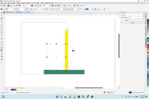 |
To ensure that the slots on the bottom of the side pieces on the iPAD case were correctly aligned with the position on the front door, we went back to the iPAD case design file in Corel Draw and grouped them. For the area of the front door, we made a rectangle with dimensions of 19.437” x 21.93”. This allowed the front door to lay flush with the upper surface of the Wheel-O-Bits box. Nidhie and I carefully measured where we wanted the iPAD case placed on the front door by taping the iPAD case together and marking its position on the door with tape. We then measured the distance from the bottom and the right side of the door. We made yellow and green spacer rectangles to correctly align the iPAD case’s bottom slots. |
 |
Using the dimesions of the hinges, we created a small rectangle with three screw holes. We grouped the four items and copied and pasted it twice so that there were three in all. We placed the first hinge in the center of the right vertical side by sliding it along the right-side line until the “midpoint” alert appeared. Since the hinges really just needed to be placed in nearly equal distances, we again utilized a recagngular spacer to ensure the top and bottom hinges were the same distance from their horizontal lines. |
 |
This shows the final design for the front door. We removed the rectangles around the hinges (leaving just the screw holes). We thought about rastering the hinge positions in addition to vectoring the screw holes, but we realized this would not look as asthetically “clean”. |
| This shows us test-cutting the front door case on cardboard. We found that the iPAD case we previously designed fit perfectly in the front door, and its position was also perfect. |
Nidhie and I used Weld-On #16 Thickened Acrylic Glue to glue all of the pieces together. We were so excited about how nice it looked and how well the designs fit together.
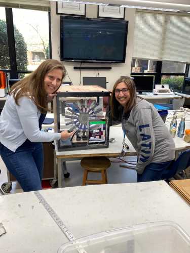 |
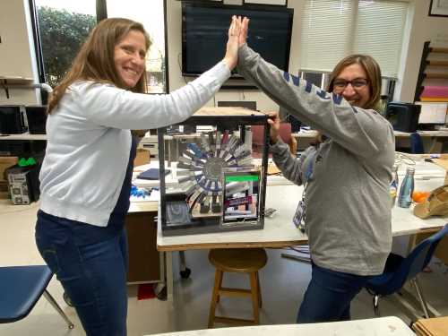 |
|---|---|
| Success Picture #1– It works! | Success Picture #2– Great team work! |
To see the work of our who group, please visit our site.
Arduino and Electronics Controls
After Avery Horvath had designed the code and wired the two Arduino Uno’s with the NEMA17 Stepper Motor (with driver), I made the following drawing of her circuitry.
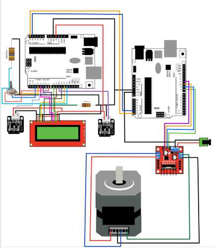
Avery and I then began soldering the electronics for the Wheel-O-Bits.
The following table and images show some of the steps of soldering the circuitry of the “Wheel-O-Bits”.
| Image | Description |
|---|---|
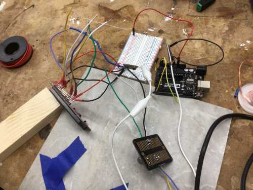 ) ) |
This shows our soldering midway through the process. We needed to stop at this point and retrieve the limit switch (on the piece of wood) to ensure it worked before moving forward with the soldering. We initially were planning to solder the wired directly onto the Arduino pins, but we wound up making a change to that plan later on. |
 |
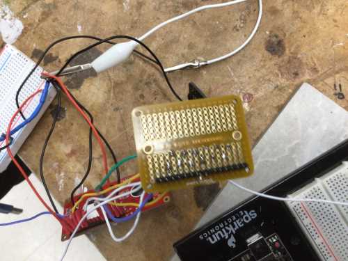
This image shows our idea of trying to use a perforated board (in lieu of the breadboard we had been using). We attempted to use male header pins with it, but we realized (sadly a few wires into it) that we did not account for the “space” between pins 7 and 8. The male header pins did not fit into Ports B and D in the Arduino Uno. We tried modifying this by removing a pin, but the space between pins 7 and 8 was not the same width as the space between other pins. |
 |
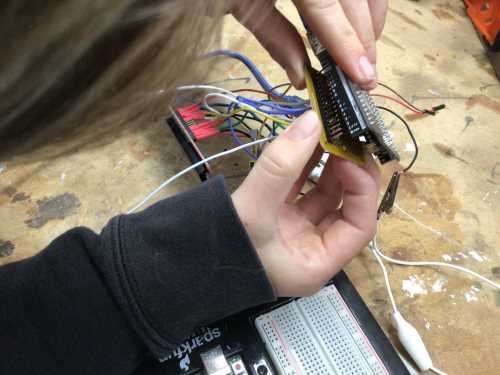
Avery was able to bend the male headers so that they would indeed fit through the perf board. In doing this, we were able to quickly run diagnostic tests as we soldered the remaining components, and we were not having to re-wire between tests and adding other components/wires. |
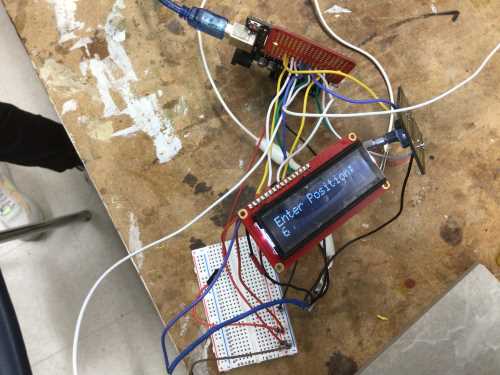 |
This shows the first test we ran with the LCD after wiring the pins and components that would be operated by Arduino 1. |
 |
Although this image shows the LCD positioned upside down, this shows all of our soldering complete (outside of wiring the three wires with/to the two limit switches). |
## Adding Neopixel Strand to Wheel-O-Bits– Nidhie Dhiman and Barbara Morrow
Using Nidhie Dhiman’s SAMD11 and ATTiny 412 PCB’s we decided to add 28 (WS2812) Intelligent Control LED Integrated Light Sources to the upper front area of the “Wheel-O-Bits” Asset Management System. Since Nidhie had used this for her Outputs Week, we felt we could easily do this. While it did take less than an hour to get the Neopixels finctioning as planned, we did run into a couple of problems.
When we tried to upload Nidhie’s code, it contained a loop, and we were not sure how to go about removing the loop.
One of Barbara Morrow’s students (J.R.) had found and shared LED Strip Effects Generator, which is a quick and easy way of generating Arduino code for a strip of LED’s. We were able to use this site to generate the following code:
#include <Adafruit_NeoPixel.h>

class Strip
{
public:
  uint8_t   effect;
  uint8_t   effects;
  uint16_t  effStep;
  unsigned long effStart;
  Adafruit_NeoPixel strip;
  Strip(uint16_t leds, uint8_t pin, uint8_t toteffects, uint16_t striptype) : strip(leds, pin, striptype) {
    effect = -1;
    effects = toteffects;
    Reset();
  }
  void Reset(){
    effStep = 0;
    effect = (effect + 1) % effects;
    effStart = millis();
  }
};

struct Loop
{
  uint8_t currentChild;
  uint8_t childs;
  bool timeBased;
  uint16_t cycles;
  uint16_t currentTime;
  Loop(uint8_t totchilds, bool timebased, uint16_t tottime) {currentTime=0;currentChild=0;childs=totchilds;timeBased=timebased;cycles=tottime;}
};

Strip strip_0(28, 2, 28, NEO_RGB + NEO_KHZ800);
struct Loop strip0loop0(0, false, 1);

//[GLOBAL_VARIABLES]

void setup() {

  //Your setup here:

  strip_0.strip.begin();
}

void loop() {

  //Your code here:

  strips_loop();
}

void strips_loop() {
  if(strip0_loop0() & 0x01)
    strip_0.strip.show();
}

uint8_t strip0_loop0() {
  uint8_t ret = 0x00;
  switch(strip0loop0.currentChild) {
  }
  if(ret & 0x02) {
    ret &= 0xfd;
    if(strip0loop0.currentChild + 1 >= strip0loop0.childs) {
      strip0loop0.currentChild = 0;
      if(++strip0loop0.currentTime >= strip0loop0.cycles) {strip0loop0.currentTime = 0; ret |= 0x02;}
    }
    else {
      strip0loop0.currentChild++;
    }
  };
  return ret;
}
This code did not work. As we continued to troubleshoot, we wound up using the code Nidhie originally had. We felt that the issue was that the generated code above was trying to program via an ISP programmer. The programmer we were using was set up to be UPDI. Tom Dubick assisted us in removing the loop that was causing issues. The code we used is shown below.
#include <Adafruit_NeoPixel.h>

class Strip
{
public:
  uint8_t   effect;
  uint8_t   effects;
  uint16_t  effStep;
  unsigned long effStart;
  Adafruit_NeoPixel strip;
  Strip(uint16_t leds, uint8_t pin, uint8_t toteffects, uint16_t striptype) : strip(leds, pin, striptype) {
    effect = -1;
    effects = toteffects;
    Reset();
  }
  void Reset(){
    effStep = 0;
    effect = (effect + 1) % effects;
    effStart = millis();
  }
};

struct Loop
{
  uint8_t currentChild;
  uint8_t childs;
  bool timeBased;
  uint16_t cycles;
  uint16_t currentTime;
  Loop(uint8_t totchilds, bool timebased, uint16_t tottime) {currentTime=0;currentChild=0;childs=totchilds;timeBased=timebased;cycles=tottime;}
};

Strip strip_0(28, 6, 28, NEO_RGB + NEO_KHZ800);
struct Loop strip0loop0(0, false, 1);

//[GLOBAL_VARIABLES]

void setup() {

  //Your setup here:

  strip_0.strip.begin();
}

void loop() {

  //Your code here:

  strips_loop();
}

void strips_loop() {
  if(strip0_loop0() & 0x01)
    strip_0.strip.show();
}

uint8_t strip0_loop0() {
  uint8_t ret = 0x00;
  switch(strip0loop0.currentChild) {
  }
  if(ret & 0x02) {
    ret &= 0xfd;
    if(strip0loop0.currentChild + 1 >= strip0loop0.childs) {
      strip0loop0.currentChild = 0;
      if(++strip0loop0.currentTime >= strip0loop0.cycles) {strip0loop0.currentTime = 0; ret |= 0x02;}
    }
    else {
      strip0loop0.currentChild++;
    }
  };
  return ret;
}
| Future Development Opportunities |
|---|
| Re-design bit box caps with thicker grip at their bases |
| Mill PCB’s with microcontrollers that would reduce down to one board |
| Generate a design that can house more bits |
| Shorten bit boxes to reduce outer mass |
| Prevent user from removing bit prior to checking it out |
| Adapt outer casing for wall-mounting to create a lower profile |
| Add more lighting effects with enhanced lighting (lights chasing the wheel) |
To see our group work with mechanical design/machine design, please visit our site.
Links to Files: Datasheets CDRs STLs GCodes