10.0. Outputs
This week, we were given the assignment to add an output device to a microcontroller board you’ve designed and program it to do something. A few weeks ago, I was able to get my SMD RGB LED to light and pulse the colors of the rainbow. I had thought about using that RGB PCB for this week’s assignment, but in a discussion with Dr. Fagan on March 30, he stated he wanted me to get my stepper motor working this week. So I set off to glean as much information about stepper motors that I could in the time I had.
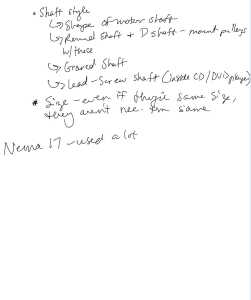
In my final project (the SpaceX Launch Alert), I plan to use at least two NEMA17 stepper motors. The first think I did was watch “Nema 17 Stepper Motor with Arduino CNC Sheild V3 (A4988 Driver) | 100% Working Arduino Code”. In this video, I learned some good information about the CNC-shield; I will likely use one of these with the 2 motors in the final project. I plan to have movement in two axes (X and Y) with the NEMA17 motors, and I will potentially use another stepper motor (possibly to mimic the hydraulic lift of the Falcon 9 rocket into launch position by Spacex’s Launcher Erector Vehicle).
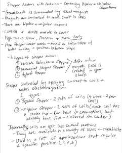
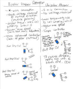
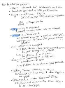
Tom Dubick compiled a list of tutorials for all of the Charlotte Latin School Fab Academy students. I watched “Stepper Motors with Arduino - Controlling Bipolar & Unipolar stepper motors” and took the following notes.
 |
 |
|---|---|
 |
 |
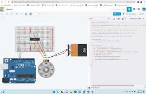
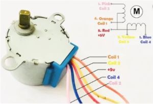
I recently realized that TinkerCAD Circuits now has stepper motors and ATTINY 412’s in it, and I wanted to do a simulation in TinkerCAD before using actual materials. I did an Internet search and found “Stepper motor simulation in TinkerCAD”. I followed this tutorial and set up the circuit as shown in it. Instead of using an ATTINY 412, I used an arduino with an L293D stepper motor driver and Small Reduction Stepper Motor - 5VDC 32-Step 1/16 Gearing. (I think this is the correct identification of the stepper motor in TinkerCAD because it is the only one I could find that had five wires with the same matching colors).
 |
 |
|---|---|
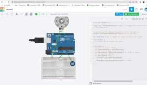
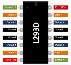
| In this example, the code uses a “stepper.h” file and utilizes pins 8, 9, 10 and 11 of the arduino. I realized from this that I should understand the pinout for the L293D stepper motor driver (shown below). | A potentiometer is used to control the stepper motor in this example. There is no motor driver utilized, and a “stepper.h” file is used here too. |
 |
 |
The next evening, March 31, I was ready to do some work with actual materials. During COVID quarantines, our students were given Elegoo Starter Kits as they worked from home. I had one of these kits in my possession, and it had a 28BYJ-48 Stepper Motor with Stepper Motor Driver Board that uses a ULN2003 IC.
In this video (below), I used an Arduino (Sparkfun Red Board), a 28 BYJ-48 5V Step Motor, and a ULN2003 Motor Controller Board. The code used the “Stepper One Revolution” from Arduino and Stepper Motor Configurations. I wired this smaller stepper motor directly to the Arduino as I had learned from the TinkerCAD exercises.
I was very excited that this worked on the first try. I decided to try one of the two codes from the TinkerCAD activity using the same materials.
||
The motor was seemingly trying to rotate when I tested it again, and I could feel it vibrating, but spinning never occurred. The video below shows this test.
||
I again attempted to get the same Arduino code working (shown in video below). I started to notice the four LED’s on the Motor Controller Board, and I compared their behavior from the first video where the stepper motor worked. Here, the LED’s seem to be “muttled” and the stepper motor does not seem to be working properly. In the first video, the LED’s blink in an alternating/controlled fashion.
||
In one final test with the small stepper motor (below), there seemed to be a short or loose connection in one of the jumper wires. The LED’s on the Motor Controller Board continue to show electrical “confusion”.
||
It was now Friday, April 1, and I was excited that I at least had one small stepper motor working, but I really wanted to get one of the NEMA17 motors working. I also needed to program the stepper motors without the use of an Arduino board, and I started to translate how that would happen from the Arduino to the pins on my ATTINY 412 PCB. Since the small stepper motor used four pins on the Arduino board, I thought about the remianing number of available pins on my ATTINY412 PCB’s, and I raised this concern that I would need at least four of those remaining pins to Tom Dubick. I also explained that I will likely need at least two stepper motors (and potentially three) in my final project. Tom Dubick suggested I look at using an ATTINY 1614.
 |
 |
|---|---|
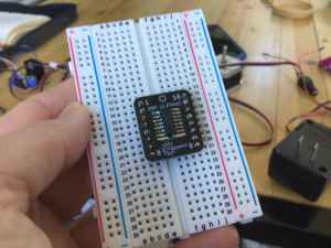
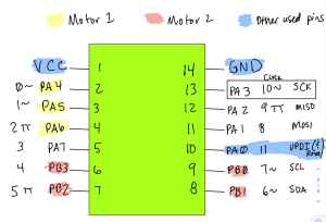
| I looked at and re-drew the pinout for an ATTINY 1614 chip, and read portions of the datasheet for it. | I then soldered an ATTINY 1614 chip to an SOIC board and placed it into a breadboard. |
I was having difficulty understanding how I was going to wire the arduino to the ATTINY 1614 chip in the breadboard, and I looked at this “How to use Arduino Uno” for help. I had finished teaching for the day (still Friday, April 1), and I sat with colleague/classmate, Nidhie Dhiman asn she was also troubleshooting her project for this week. At that time, Nidhie was adding her “config” file to her neopixel strand code, and she was much further along than I was. Working next to her, I learned that I too would need a “config” file once I had replaced the arduino in my setup with my SAMD11 PCB. In that session, Nidhie sent me this link that showed me how to open a new tab in the Arduino IDE to add the “config” file once I had it. I searched the Internet for a “stepper.h config” file, and found this site which had a config.h file under “stepper.c file”. I would use this a couple of days later.
On Saturday, April 2, I began looking at video tutorials about the NEMA17 stepper motor. One video, “DIY Pen Plotter with Automatic Tool Changer | Arduino based CNC Drawing Machine”, was ideal in helping me to see how NEMA17 stepper motors were used in three axes. My final project should include NEMA17 stepper motors in only the X and Y axes, but the movement and carriages used in this video showed a different design from what I had envisioned. I planned to add some of the images from this vidoe to my final project page.
I watched “L298n Dual H-Bridge Motor Driver : DC Motors : PWM : Stepper Motors : Eye-On-Stuff”. This Motor driver would allow me to use two stepper motors, and it might be a good option if only two are used in my final project. However, my goal was to get one NEMA17 motor working before attempting to incorporate a second one.
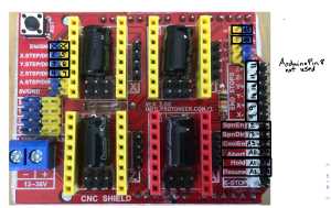
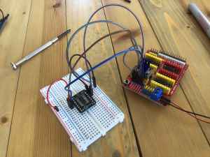
In this video–Arduino CNC Shield V3 and A4988 Hybrid Stepper Motor Driver, CNC Shield pinout, wiring, code, DIY, there was great help in understanding how the CNC Shield worked with the Arduino board. I decided to mimic what was being done in this video using the Arduino (Sparkfun Red Board), Two Trees NEMA 17HS4401 Stepping Motor, A4988 W/Heat Sink Module, and CNC Shield that I had in my possession at home. One thing I learned from this video was how the Arduino board was connected to the CNC Shield. I decided to take a photo of the CNC Shield I had and make the Arduino pin notes on it.
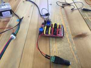
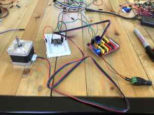
I began to assemble the NEMA17 Stepper Motor with the CNC Shield and 12V Power Supply. The images below show the steps I took to prepare this “apparatus”.
| Image | Description |
|---|---|
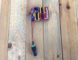
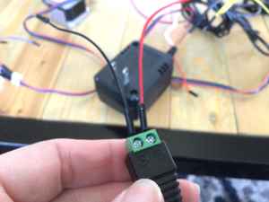 |
I connected the red PWR wire to the (+) terminal and the black GND to the (-) terminal. This would be plugged into the 12V power supply. |
 |
I connected the PWR and GND wires to the CNC Shield. |
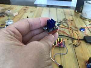 |
This shows how I attached a heat sink to the Big Tree Tech TMC 2208 V3.0 Motor Driver. |
 |
I placed the Big Tree Tech TMC 2208 V3.0 Motor Driver to the CNC Shield (with the Pwr and GND wires also attached). |
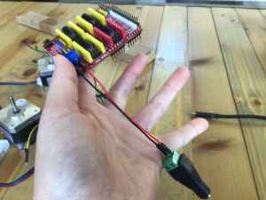
 |
This shows the wires of the NEMA17 Stepper Motor alongside the CNC Shield apparatus. |
 |
Here, I connected the black wire to the GND rail and the red wire to the PWR rail. |
 |
With the ATTINY 1614 soldered onto the SOIC and placed into the bread board, I wired the pins to the proper pins. |
 |
I connected the NEMA17 Stepper Motor to the CNC Shield. |
The following videos show a long (a very, very long) series of tests done on Saturday, April 2, along with short explanations of what was done.
In this video clip, I verified and loaded the code for one NEMA17 Stepper Motor. I really wanted this code to work because I was unsure if the “stepper.h”/”config” file was going to work if I was forced to use it.
||
After loading the “One Stepper” code onto the Arduino Board, I placed the pins of the CNC Shield into the pins of the Arduino board. The pins of the NEMA17 Stepper Motor were plugged into the upper left portion (in the “X” quadrant) of the CNC Shield. Finally, I plugged the 12-volt power supply into the CNC Shield. The video below shows that when I did all of this, the motor turned on, but it eventually (seemingly) shorted out/stopper vibrating. The central axis never turned.
||
In this video, I tried the code once again on the NEMA17 Stepper Motor. I wondered if I had the Big Tree Tech TMC 2209-v.3.0 (with heat sink) upside down. After trying it in two different configurations, the motor only vibtated but the central axis still did not spin. This only happened with the “En” portion of the Big Tree Tech TMC 2209-v.3.0 (with heat sink) was aligned with the “En” on the CNC shield. In this “position”, it seemed incorrect to me because the writing on the Big Tree Tech TMC 2209-v.3.0 was upside down when the two “En” (Enable) “corners” were aligned.
||
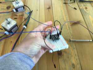
Frustrated after watching numerous videos about the CNC Shield and NEMA17 Stepper Motors, I decided to return to the smaller stepper (28BYJ-48) motor I had been using with the Arduino board. To start the work with this smaller (28BYJ-48) stepper motor again (and maybe needing to gain confidence after being deflated by the NEMA17), I loaded the code once again. This led to numerous tests, and eventually me working up the courage to try my SAMD11 programmer in place of the Arduino board. The image below shows the “build” of the small 28BYJ-48 Stepper Motor and the Stepper Motor Driver Board.
||
As mentioned earlier, I knew that I was going to have to use the “config” file in a new tab in the Arduino IDE when I substituted my SAMD11 programmer in for the Arduino board. This vidwo below shows me testing the config code with the “One Revolution Stepper” (in place of the “stepper.h” arduino library). This action resulted in an error with the UPDI connection.
||
I realized that I had the VCC and the UPDI pins switched on my SAMD11 programmer. Once I corrected this, the code uploaded to the board properly. This was literally the only thing in Fab Academy that did not take an hour to solve.
||
Thinking about the pins, I did an Internet search and found this link that made me realize I had the wrong pins connected to the stepper motor. I checked the wiring of the 28BYJ-48 Stepper Motor and the Stepper Motor Driver Board, and it seemed to be correct. I changed the four pins of the Stepper Motor Driver Board from 0, 1, 2, and 3 to 4, 5, 6, and 7, and this at least caused the LED’s on it it to light up. I had to be very certain when pinning these pins. The SOIC had sixteen pins, but the ATTINY 1614 only had fourteen pins. The last two “spots” were empty, and it would be easy to accidentally place one of the pins in the empty spots.
||
I made adjustments, and I wasn’t sure the code was actually controlling anything. I re-uploaded the code, and this time, I got the UPDI error again. I was very irritated because I thought I had already rectified this issue.
||
In the video below, I realized that the ATTINY 1614 SOIC was not properly pushed into the breadboard. (This made me pretty much hate breadboards). The 28BYJ-48 Stepper Motor started to vibrate. I started to notice how the LED’s were behaving in all of these tests, and I remembered that the magnet passes over two sets of coils in the stepper motor. The “back and forth” movement/pattern of the LED’s on the Stepper Motor Driver Board was giving me an indication of what was happening inside.
||
I wondered if I had changed the pins of the Stepper Motor Driver Board too soon (while there were other errors existing). I re-pinned to pins 0, 1, 2, and 2 and successfully uploaded the “config” file to the ATTINY 1614 chip again.
||
Really wanting the 28BYJ-48 Stepper Motor to spin properly (clockwise and then counterclockwise), I– once again– went back to pins 4, 5, 6, and 7. And once again, I got the UPDI error.
||
Being quite the pro at resolving the UPDI error issues, I was quickly able to get the 28BYJ-48 Stepper Motor to pulse correctly, but still it would not spin around the cetnral axis. I could also see that the LED’s on the Stepper Motor Driver Board were very “controlled” and clearly repetitive. I knew that I was getting close to figuring out the proper way to connect and code it.
||
To satisfy my curiosity, I decided to really examine the behavior of the LED’s on the Stepper Motor Driver Board if I reversed the current. I was still very puzzled as to why there was not spinning of the central axis.
||
When I looked closer at the black tape on the central axis, I noticed that it was actually “twitching” in the correct directions albeit very slightly. The cideo below shows a closeup of this twitching.
||
In the next test, I was able to get the black tape to visibly rotate in one full step as it should. The video shows this. However, the code tells the 28BYJ-48 Stepper Motor to rotate first clockwise and then counterclockwise. Still, the 28BYJ-48 Stepper Motor only moved in the clockwise direction (as seen in the video below).
||
Now that I had the code halfway working with the 28BYJ-48 Stepper Motor, I wanted to see what changing the steps in the code changed in its behavior. In the video below, I changed the steps per revolution to 100 (cut in half). This video shows the result.
||
I decided (in the video below) to once again cut the steps per revolution in hald (down to 50).
||
I reduced the steps per revolution down to 5 in this video.
||
When I did the previous tests, the patterns of the LED’s were so clear. I was able to show this clearly in this video. Since the central axis only spun sometimes, I wondered if the 28BYJ-48 Stepper Motor was faulty.
||
This thought led me to increase the number of steps per revolution. The video below shows what happens when this value is increased to 250 (from the original 200 steps per revolution in the original code).
||
In the video below, I increase the number of steps per revolution to 400 (doubling the original 200).
||
And finally, I increased the number of steps per revolution to 500. The 28BYJ-48 Stepper Motor seemingly stopped functioning, and I wondered if I had reached (or exceded) its limits.
||
This video shows the central axis of the 28BYJ-48 Stepper Motor alternating directions and FINALLY WORKING AS INTENDED. Now it was time to ditch the bread board and design the PCB.
||
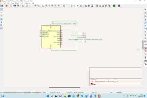
As I thought about the design of the PCB, I decided to place an ATTINY 1614 chip (only) in the center of it. I opened KiCAD, and I added the symbol for the ATTINY 1614 chip. Of the fourteen possible pins, three would need to be occupied by the VCC, GND, and the UPDI pins (pins 1, 14 and 10 respectively). This left eleven pins that I could use– eight of them I tested extensively for an entire day. I put a 3-pin male header on the “top” of the PCB and connected the traces from VCC, GND and UPDI to them. I then grouped Arduino pins 4, 5, 6, and 7 on the “bottom” of the PCB.
 |
 |
|---|---|
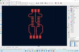
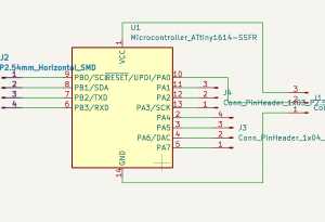
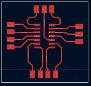
After I created this PCB (that looked like the top view of Thanksgiving Day turkey), I decided to also group (Arduino) pins 0, 1, 2, and 3 (ATTINY 1614 pins 2, 3, 4, and 5 respectively) along with (Arduino) pins 4, 5, 6, and 7 (ATTINY 1614 pins 6, 7, 8 and 9 respectively) so that either set of pins could be utilized to interchangeably run either one motor or two motors at the same time. I then grouped the three remaining pins– Arduino pins 8, 9 and 10 (ATTINY 1614 pins 11, 12 and 13 respectively). With each group of pins, I placed a set of male headers in an arrangement of either three or four and connected the headers to the legs of the ATTINY 1614 chip with 0.4 mm traces.
 |
 |
|---|---|
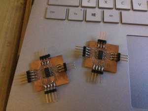
On Monday, April 4, I milled and stuffed two identical PCB’s (as shown below) at the Charlotte Latin School Fab Lab.
||
On Tuesday, April 5, I began testing my PCB’s with my 28BYJ-48 Stepper Motor and Stepper Motor Driver Board. The following videos show my tests done. In the end, I needed to have more power in the Stepper Motor Driver Board.
||
||
||
||
IT IS WORKING PERFECTLY!
After completing all of my individual work for this week (and not being able to get my NEMA17 Stepper Motor working correctly), it was when I was working on our group project with colleague/classmate– Nidhie Dhiman– when I realized what the issue was with my work with the NEMA17 Stepper Motor. For the Mechanical-Machine Design weeks (weeks 11 and 12), our group was using a NEMA17 Stepper Motor to spin a “wheel” for organizing the desktop milling machine bits.
NOTE: The following information will also posted on my work for next week’s Mechanical Machine Design Group Project as part of my portion of work done on our project.
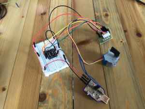
As Nidhie Dhiman and I worked to get one NEMA17 Stepper Motor working, we used the same 12V power supply with an L298N Motor Driver attached to the NEMA17 Stepper Motor. Since I had not used the L298N Motor Driver with a NEMA17 Stepper Motor, I researched and relied heavily upon a few wesbites.
The first website I used – called ““SKR Pro V1.1 - TMC2208 UART v3.0 (BigTreeTech)” was useful in understanding the rationale behind the wiring we would use for the NEMA17 Stepper Motor. However, this wound up not be an ideal site in the end because a CNC Shield was not utilized.
I then searched again and found this site– “MC2209 and TMC 5160: Guide for MKS Gen L and SKR V1.3”; this too wound up not being great because he was really only comparing the different motor drivers that could be used in conjunction with NEMA17 Stepper Motors that were being replaced on a 3D printer. It was after this video that I began to find more useful information.
This site showed me we needed a GRBL file when using NEMA17 stepper motors. I followed this link, and I was eventually sent to this github site that contained the source code for the .h files and an extensive collection of C files. In addition to this, I found a “GCode Sender” site that would be useful for mhy final project in developing GCode for coordinates in my SpaceX Launch Alert System. This site may also be fruitful in developing coordinates for our “Milling Bits Storage Concept”.
“This final site” that I found was incredibly helpful in how to wire the NEMA17 Stepper Motor to the L298N Motor Driver. Although this viewo showed how to connect two small DC motors to the L298N Motor Driver, Nidhie Dhiman and I were able to logic our way through the connection of just one NEMA17 Stepper Motor. This site actually showed a diagram of how the NEMA17 Stepper Motor should be connected. After wiring it, we eventally got the NEMA17 Stepper Motor to respond (similarly to how my NEMA17 Stepper Motor had responded with the CNC Shield a few days ago). The motor would vibrate for a short period (the central axis spattering back and forth in a “confused” motion), and then eventually “die out”, stopping the vibration altogether.
After several attempts to remedy this, we realized that the motor responded better when Nidhie Dhiman held her fingers under the IN1, IN2, IN3, and IN4. She seemingly was completing the circuit whenever she touched the ends of the IN1 and IN4 pins with a forefinger on each hand. It dawned on me that she was literally conducting the current through her fingers, and I remembered that we had removed the lateral headers on each side of the EN1 and EN4 pins. We quickly found the headers and repositioned them back onto the L298N Motor Driver to the left of the IN1 pin (the ENA pin) and to the right of the IN4 pin (the ENB pin).
After this, we plugged it all in again with the 12V power supply, and the motor continued to “die out”. We had a conversation with Dr. Adam Harris, and as we examined the power supply, Dr. Harris realized we had an AC 12V power supply and we were trying to use with a DC motor. Ugh! Feeling incredibly dumb, Nidhie Dhiman searched the 12V power supplies, and she was able to find onlhy one that was a DC 12V power supply. We plugged this in, and the NEMA17 Stepper Motor then began fucntioning beautifully as “commanded” in the Stepper One Revolution Arduino file (attached below). The follwing video shows our work and FINAL SUCCESS of getting a NEMA 17 Stepper Motor to function properly with a L298N Motor Driver.
||
Our group assignment this week was to measure the power consumption of an output device. To see our work on this assignment, please visit our site. To see my work on this group project, please visit this site.
Links to Files: Datasheets Arduino_config GRB Files