2.0 Computer Aided Design- Modeling A Possible Final Project
This week, I began work in creating a design for my final project in Fusion 360. One of my students, M.K. (initials), created a CNC Drawing Machine for her final project this pas Decemeber. Her work contained some of the mechanisms I could use in my project– mainly the servos and guide rails or double rods. To start, I watched this tutorial from DIY Machines that M. K. used in generating her CNC Drawing Machine. I would like to test out using both the rails and the two-rod mechanism in my project, and I was thinking that for the first iteration, I would test out the rails for the horizontal movement and vertical movement of my Falcon 9 rocket. Although M. K. used the .stl files included in the tutorial, I wanted to design similar pieces that fit my project needs and specifications.
At Charlotte Latin School , we have scaffolded our engineering courses such that they spiral and advance in skill difficulty. For Computer Aided Designing (CAD), we begin with TinkerCAD in 7th grade, and being a Google Suite School, we move to Google Sketchup in the 8th grade. When students complete our Engineering Design Methods I class (the first level available for a high school student at Charlotte Latin School), they become fluent in Fusion 360. Having exposure to all three of these CAD tools, I am the least knowledgeable about Fusion 360, and I decided that this would be a good place to start with designing parts for my project in that it would take me out of my comfort zone.
Before I began my first design, I took a number of photos of M. K.’s CNC Drawing Machine from different angles so that I could somewhat replicate the mechanics (if possible). I needed to know the specifications of the parts I anticipate to include in my SpaceX Launch Alert. I looked up the following parts and their specs (if digitally available online). For the linear rail, I ordered a 30 cm rail, but I did not know the width. I used digital callipers to measure the width of M.K.’s linear rail used in her CNC Drawing machine. That value was 9.35 mm, so I rounded it to 9.5 mm (to allow for some movement).
-
4-8 x15 x 45mm Linear Bearing: These are used –most likely– for iteration 2– to hold the long rods. These may not be needed at all.
-
2-8 x 15 x 25mm Linear Bearing: These will be used in conjuction with the Servos in turning the belt for movement of the SpaceX Falcon 9 Rocket.
-
2-12v Nema 17 stepper motors: These stepper motors will be the main objects generating the linear movement of the Falcon 9 Rocket.
-
GT2 Timing belt and pulleys: We already had the timing belt in the Charlotte Latin School Fab Lab, so this was not ordered. This timing belt has “teeth” on it so that, when wrapped around a circular “joint”, it is held in place. It is going to be very important that the width of the circular joint is correct. The timing belts will be wrapped around the ball bearings housed within the 3D designs for the horizontal ends 1 & 2 and vertical ends 1 & 2.
-
2-Micro servos: I ordered these to determine if this smaller motor could sufficiently power the belts with the weight of the Falcon 9 Rocket on it. I am doubtful that they will have enought torque and fluid movement to make the rocket move as slowly as I need it to move.
-
2-Stepper drivers - TMC2208: These will control the rotation of the stepper motors so that they spin smoothly and generate the movement of the timing belt that the Falcon 9 Rocket is strapped to.
-
2-Contact switches: Contact switches will be at the ends of the Falcon 9 Rocket’s horizontal and linear lengths. Once triggered, these contact swtches will hopefully trigger the vertical sequence after completing the horizontal sequence, and end the vertical sequence/initiate the resetting of the device (reversing the spin direction of the stepper motors).
-
1-Arduino CNC Shield: I am not sure if this is needed, but I ordered one (to have and not need rather than need and not have).
-
4-8mm Chromed Steel Rod (35cm x2 & 5.5cm): These will likely be for the second iteration of the design. I felt like I should try using the linear rails for the horizontal and vertical movements of the Falcon 9 Rocket first. I fels like there was less likelihood of a failure with just the linear rails in each plane. If these are used, I will modify the end postions so that the rods fit inside the 3D-printed parts and allow for some “wiggle” room to prevent breakage of the PLA.
-
2-30cm long linear rails with block - MGN12H: These will be used in the first iteration of the design, and it is my hope that the movement of the blcoks on the linear rails will provide smooth and slow movement of the Falcon 9 Rocket.
-
12v power supply: This will be the power source for the entire device.
-
Barrel Connector - Female: This will be used to connect my circuit boards and servos to the power supply.
Fusion 360
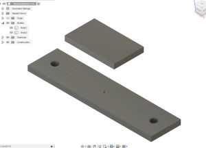
Although I have completed eight of Kevin Kennedy’s Learn Fusion 360 Tutorials in preparation for Fab Academy, I was really nervous in being able to navigate such a robust CAD software, and I definitively did not make this first 3D design efficiently. (After all, two of the eight tutorials I completed ended up in faulty design issues that I could never resolve– espcially with the ice cube tray and the whiskey bottle). I had a few spots of trouble as I modeled my “Horizonatal End 1”; generally, the overall shape of this design is simiar to the one in the DIY Machines- CNC Drawing Machine Tutorial. I started with making the horizontal base piece. I knew the dimensions I wanted the outer casing to be, and I made the base dimensions slightly smaller. I have included my reasoning for each design aspect below.
| Image | Fusion 360 Steps |
|---|---|
 |
|
| 1. Draw a Center Rectangle with dimensions of 30 mm x 125 mm. | |
| 2. Extrude the rectangular base 5 mm. | |
| 3. Create a Center Circle with a diameter of 6.35 mm, and add construction line down the middle of the bar. | |
| 4. Add a vertical construction line down the middle of the bar. | |
| 5. Under “Create” select “Extrude”. Add a (-6 mm) value. | |
| 6. Under the “Create” tool, select “Mirror”. Select both of the circles as the “Profiles” and select the newly created construction line running through the middle of the bar. | |
| 7. Select “OK”. | |
| 8. Since the extrude “Distance” is – 6.0 mm, it will “hole” the areas. (This will make a hole going through the 5 mm base. | |
| 9. Hit “Finish Sketch” in the upper right-hand corner. |
| Image | Fusion 360 Steps |
|---|---|
 |
|
| 1. Select “Construct”, and choose “Offset Plane”. | |
| 2. In the “Sketch” Palette on the right, select “Construction Line” under “Line Type”. Then create a center rectangle that is 68 mm long and 30 mm wide. | |
| 3. Hit “Finish” in the upper right corner. Select “Offset Plane”. Set the distance to 40 mm. | |
| 4. 12. Select the newly created parallel offset plane, and create a center rectangle and make the dimensions 50 mm x 30 mm. | |
| 5. Extrude the newly created rectangle 5 mm to match the lower 5 mm base piece. |
| Image | Fusion 360 Steps |
|---|---|
 |
|
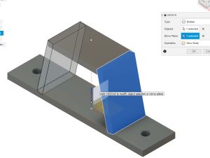
| 1. Under the “Construct” dropdown, select “Plane through two edges”. | |
| 2. Under “Create” dropdown, select 3-point rectangle and make the rectangle. | |
| 3. Select the right-side two edges from the top and bottom bars. | |
| 4. Select the newly created rectangle, and extrude it -5.0 mm, but under the “Operation” dropdown, select “ New Body”. | |
| 5. Create a construction line down the middle of the object in order to create a mirror. To do this, select “Finish”, and under the “Create” tab, mirror the slanted side as shown. | |
| 6. Create a plate off of the lateral two slanted sides. |
| Image | Fusion 360 Steps |
|---|---|
 |
|
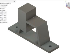
| 1. On the newly created plane, create a new rectangle and extrude this new rectangle 30 mm. | |
| 2. Construct another plane through two edges. | |
| 3. On the same plane that was just created, make another rectangle with measurements of 32.268 mm. | |
| 4. Extrude this rectangle 30 mm (to the dimensions of the previously created rectangle). | |
| 5. Select “Finish Sketch”. |
| Image | Fusion 360 Steps |
|---|---|
 |
|
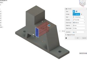
| 1. There needs to be a space to embed the 8 x 15 x 25 mm ball bearings. The timing belt will be wrapped aroung this ball bearing, and connected to the servo at the ball bearing space on the opposite side. |
| Image | Fusion 360 Steps |
|---|---|
 |
|
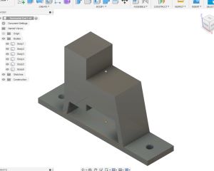
| 1. On the same plane that was used to create the switch trigger area (above), create a rectangle that is 30 x 8.1 (to form a tall, vertical-oriented rectangle). | |
| 2. Extrude this rectangle 30 mm. Be sure to select “Cut” this time. | |
| 3. Using the cursor, select the entire object and click on “Join” (above the “Modify” button). |
| Image | Fusion 360 Steps |
|---|---|
 |
|
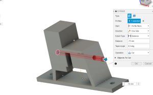
| 1. On the left side of the object, make a circle that is 5.5mm in diameter, and extrude it (making sure to select “Cut”. | |
| 2. Make a square on the top with the dimensions of 30 mm x 9.5 mm. Extrude this square -2 mm to create a “channel” for the linear rail. |
| Image | Fusion 360 Steps |
|---|---|
 |
|
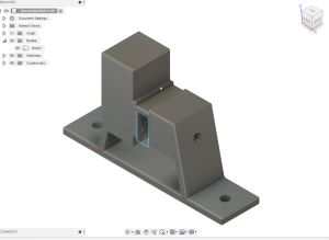
| 1. Select all 90 degree edges, and filet them with a 1 mm measurement. |
Solid Works
I have never used Solid Works.
In the spirit of challenging myself as much as possible, I decided to give it a try. Given that we have access to SolidWorks through Fab Acadmey (for a year), I went to log on, but my password did not work. After a couple more attempts, I decided to select “Forgot My Password”; I clicked on this and looked for the promised email. I never received the email. The next morning, I spoke with Tom Dubick, and I mentioned that I could not access my account. After also speaking to colleague, Nidhie Dhiman, she also could not access her newly created account (through Fab Academy). Fellow Fab Academy classmate, Charlie Horvath, is well-versed in SolidWorks, and I asked him if I could use his SolidWorks account to test it out.
To start, I watched Ultimate SolidWorks Tutorial for Absolute Beginners- Step-By-Step. As I began this video, a newer version popped up, (Ultimate SolidWorks Tutorial 2021 for Beginners (In depth explanation) Part 1), and I switched to that one instead. As I watched the tutorial, I realized that SolidWorks is similar to Fusion 360 in that all 3D objects are designed with first drawing a sketch of the shape. As I watched the tutorials, I took notes so that I could play around with SolidWorks when done. One thing unique to SolidWorks is that when you select a tool, there is a “shadow-like” visual of the tool you have selected to use. Also unique to SolidWorks, as you move the cursor around the origin, dashed blue lines appear. These lines are actually temporary construction lines; they also appear when you draw a second entity around any other entity. (In Fusion 360, you had to designate a line to be a contruction line). As more entities are added, more temporary construction lines will appear.
I then watched Ultimate SolidWorks Tutorial 2021 for Beginners (In depth explanation) Part 2. In this second part, I learned how to change: the dimensions of sketch that has already been created, the colors/change the appearance of a sketch, and how to create fillets on a sketch.
I decided to do the things mentioned in the tutorial.
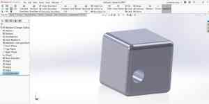
I created a 10” x 10” cube with filleted edges (radius of 1”) and a 1” through-hole in the middle of the cube. To do this, I first selected the “front plane” and activated the line tool by clicking on it once. Using five points, I drew a rectangle until it was a closed figure. In the upper left-hand corner, I selected “Smart Dimension” and clicked on it to activate it. I then clicked on one of the sides to highlight it, and I clicked again away from the rectangle to place a value of 10. I changed all four of the sides of the rectangle to have a value of 10. The following screenshot shows my design of this.
TinkerCAD
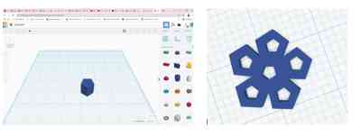
In my quest to make a bucky ball (and not having access to SolidWorks), I wanted to see if designing it would be easier in TinkerCAD– a basic and simple software. TinkerCAD is not a tool that I would readily use for my final project because it does not have robust tools (for example, placement of objects above the plane are difficult). One very frustrating aspect of TinkerCAD (that other CAD softwares have) is the ability to go back into the timeline and modify the object you are designing. In TinkerCAD, if I changed my mind about the measurements of my object, I had to keep using the “Edit” + “Undo” button. The following screenshot shows the creation of my pentagon snowflake.
Inkscape
The SpaceX Launch Alert system will need to have “housing” for all of the components. I have decided that I will laser cut this part out of either 1/8” acrylic or 1/8” plywood. I am very well-versed in Corel Draw, and once again, I decided to go out of my comfort zone and use Inkscape. This week, Dr. Gershenfeld alluded to parametric designs and algorithmic designs. The more I thought about this, I wanted to try to make the housing for my final project so that it can be cut on literally any material by changing just one setting. Believing this to be what an algorithmic design is, I decided to conduct an Internet search to learn about them. It was in sifting through the information online that I confirmed the choice to use Inlscape rather than Corel Draw. I could not find out how to do this in Corel Draw, but there were videos of how to create them using Inkscape. I began by watching Inkscape Parametric by none other than my colleague and friend, Tom Dubick. (It was completely accidental that I found his video).
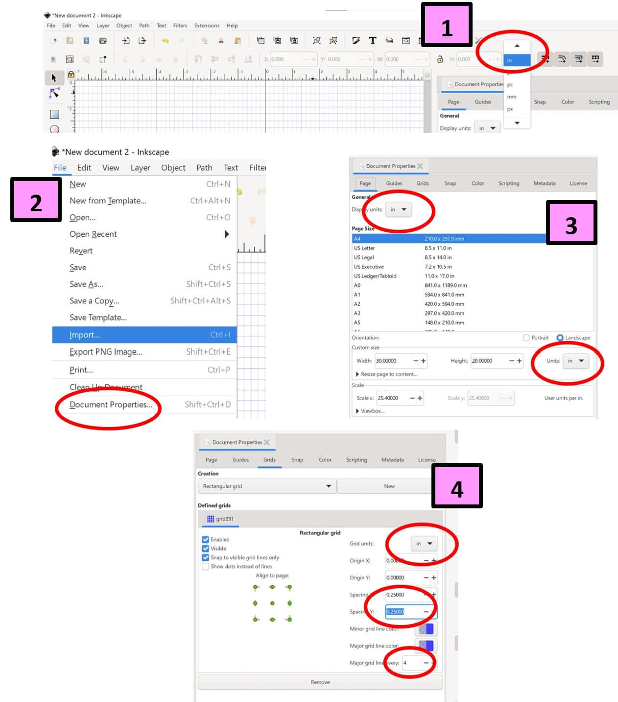
Upon opening a new document in Inkscape, the first thing that I did was change the units to inches in four places. The first place was in the upper right portion of the tool bar (as shown in Screenshot 1). In the upper left corner of the new document, from the “File” dropdown button, I selected “Document Properties. When the “Document Properties” window opened, I changed “mm” to “inches” in two places (as shown in the Screenshot 2 & 3), and I entered custom document dimensions of 40” x 40” (horizontal and vertical respectively). In the same window, I selected the “Grid” tab, and selected “New Grid”. I changed the unit there to “inches”, and changed the “Spacing X” and “Spacing Y” grid values t0 0.25 each, and I selected the number “4” under the “Major grid line every” dropdown button (as shown in Screenshot 4). These last two things mean that every minor line in the document is 0.25 inches, and every major grid line in the document in 1.0 inch. I also made sure that “Snap Grid” was turned on. (This really helped when trying to make the tabs on my electrical housing becuase I knew the small rectangles were indeed touching the large one. This is necessary for “joining” all of the small rectangles to the large one).
I was then ready to start making my electrical housing unit for my “SpaceX Launch Alert” device. I would really like to laser cut my design on colored acrylic, but I am not sure if I will use 1/8” or 1/4” acrylic. This is why I wanted create a parametric design– for the ability to interchange the material without having to redraw it if I changed my mind about the material later. For the first design, I decided to assume that I would use 1/8” acrylic, and I am choosing dimensions that are easy to scale.
Designing Bottom Piece
I started with designing the base of the electrical housing similarly to a tabbed box. I created a small rectangle with the dimensions of 0.125” x 1.0 “(as shown in Screenshot 5). I then cloned this small rectangle by selecting it and clicking on “Edit” in the upper left corner (as shown in Screeshot 6), and I selected “Clone” from the dropdown. To create the larges surface of the base, I created a larger rectangle with the dimensions of 35” x 5”. (The linear rail I plan to use in my first design is 30” in length, and this would leave 5” for creating the vertical arm– the left side of the device. Both the horizontal arm and the vertical bar of the entire unit need to house a servostepper motor with dimensions close to 2” x 2” in size). I copied and pasted the small cloned rectangle 11 times to create tabs on one of the long sides of the bottom piece.
I then tested the tabs to make sure they indeed change in size by changing the original rectangle. I changed the height of the original small rectangle from 0.125” to 0.5”. The size of the 11 cloned rectangles indeed changed size, but they now overlapped halway over the large rectangle. This actually made me realize that this was the factor I would need to change to if I decided to switch to 1/4” acrylic because the amount overhaning was now 1/4”. I wondered if the small cloned rectangles would increase in size if I joined them to the larger rectangle (choosing “Union” from the “Path” dropdown as shown in Screenshot 7), and I tested it. From this test, I learned that the small rectangles (tabs) on the large rectangle no longer function as a clone if the “Union” button is initiated. If I use 1/4”-thick material or if I do decide to change the material thickness to 1/4”, I will have to “Union” everything again before laser cutting (in either instance).
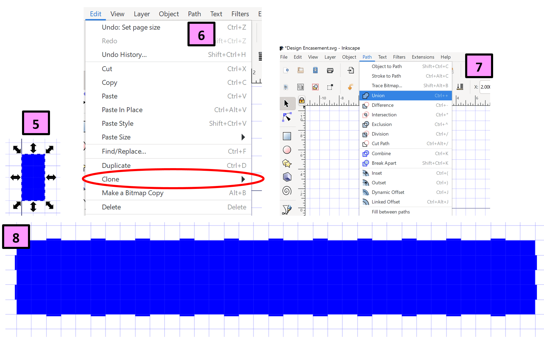
To complete the bottom piece, I simply copied the 11 small rectagles (tabs) from the top, and pasted them on the bottom (as shown in Screenshot 8). Since the eleven small rectangles were clones, the new, copied and pasted ones were also clones of the original. I completed the bottom piece by adding two small-rectangle clones to each end of the large rectangle (also shown in Screenshot 8).
Designing Sides of Horizontal Arm
To make the sides of the horizontal arm, I copied and pasted the large (35” x 5”) rectangle. It was in making this rectangle that I realized I used the wrong units! The linear rail–previously mentioned– is 30 cm long, not 30 inches! One cm is equal to 0.394 inches; I used an online conversion tool to get this value. So I went back to modify the original design. Screenshot 9 shows the change the horizontal size from 35” to 20”. I was now ready to make the sides.
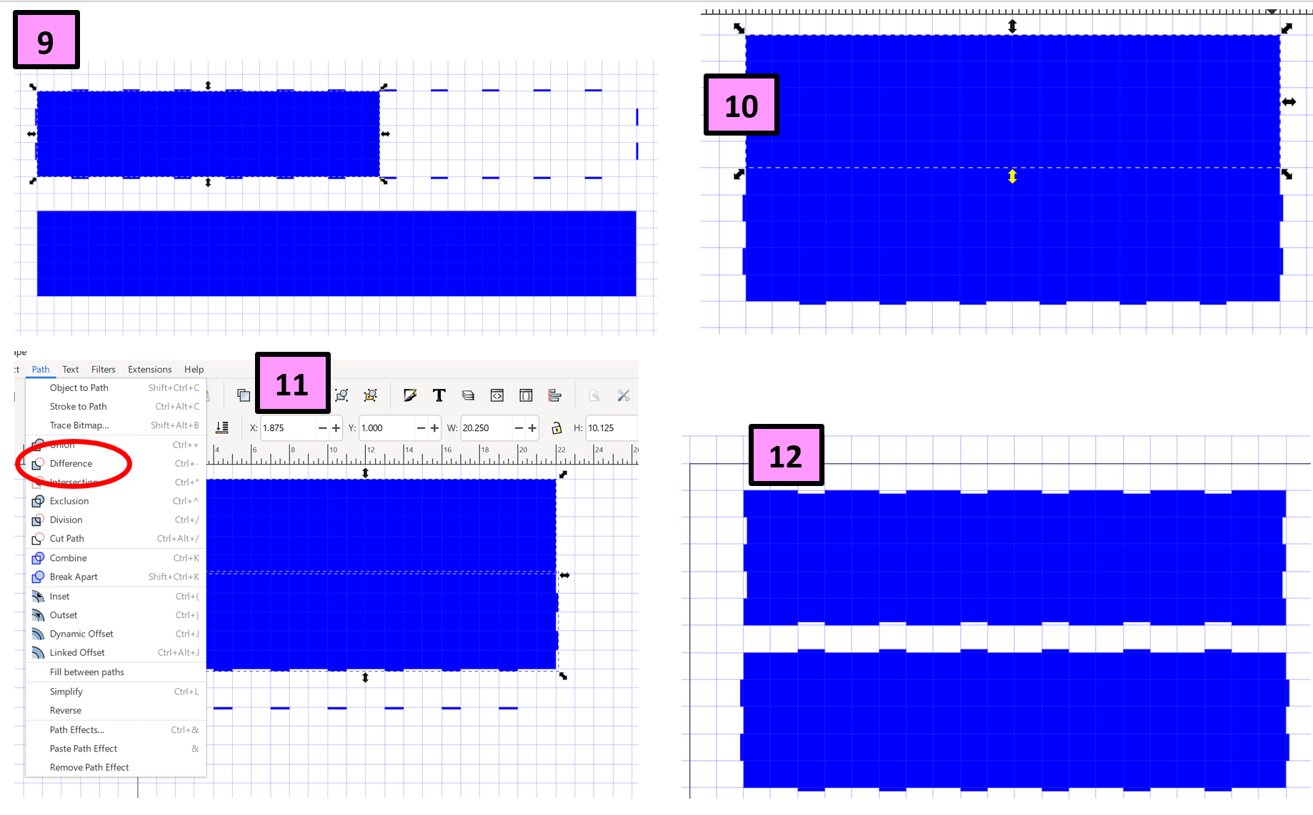
I copied and pasted the 20” x 5” rectangle, and I placed it on top of the tabbed bottom. Trying to difference the side to make it have inward tabs, I had to make sure that the tabbed bottom piece was overlapping the side rectangle. Once positioned this way, I chose “Difference” from the “Path” dropdown tool (see Screenshot 11). However, when I selected “Difference”, the bottom, tabbed part disappeard (even though the top piece now had the inverse tabs). To remedy this, I copied the bottom base, differenced the two rectangles and pasted the tabbed bottom back into the document. I repeated this with all of the sides of the rectangle. Screenshot 12 shows how the side of the horizontal housing unit looks. Then, all that needed to be done was copy and paste the newly created side for the other side. Screenshot 13 shows this.
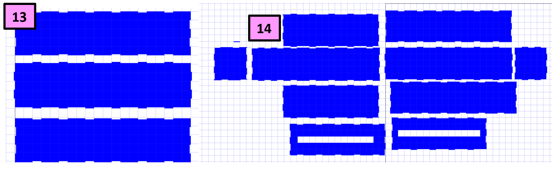
I decided to lay the pieces out according to how they will be placed together. This helped to see how the top and small end would need to be created. I made a 5” x 5” rectangle for the end piece and differenced it with the three sides that were already made. It was at this point that this design was starting to make sense to me, and I continued to make the sides as they fit together. I am pretty certain there are mistakes in this design, and I think the only way I will be able to test it out is to laser cut it on coardboard and try to fit it together. Screenshot 14 shows all of the sides together.
Corel Draw
On Monday, February 7, I had a conversation with Mr. Tom Dubick about using Inkscape for parametric drawings. As I had searched for tutorials on how to generate parametric or algorithmic designs in Corel Draw, I was not successful, and I only found tutorials for Inkscape. Tom Dubick then opened Corel Draw and showed me that the “clone” tool is also present in Corel Draw. So I decided I was going to make an artistic paramentric design in Corel Draw.
When I opened the document in Corel Draw, I immediately gave it a name, “Parametric Design”. I was appreciative of the fact that setting up documents in Corel Draw is much easier than in Inkscape. After having a conversation with my husband about parametric designs, I mentioned that I wanted to create a snowflake. Then my husband said “what about a bucky ball–in chemistry”? I did an Internet search about what a bucky ball is, and I realized I could combine my snowflakes with a bucky ball. I found this bucky ball image. After examining the structure of this bucky ball (hexagons arranged around polar pentagons), I then set out to find both a five-sided and a six-sided snowflake. In searching for a five-sided snowflake, I found Make The Edges of a Koch Snowflake With Pentagon Patterns. This seemed to be exactly what I was looking for, and I decided to try this in Corel Draw. I wondered if a six-sided snowflake could be made using hexagons?
I began drawing both a heagon and pentagon in Corel Draw. I realized that it is not as easy as simply making the shapes and arranging them into snowflakes. I had to know the external angles of each figure. IResorting once again to an Internet search, the Math Warehouse site provided the answer: the external angles of a pentagon are 72 degrees, and the external angles of a hexagon are 60 degrees. I created both figures in Corel Draw using horizontal and vertical measurements that were nearly equal in values. I created one hexagon and one pentagon, and I decided to clone them both and test them out. They worked perfectly, and I decided to make a model of the pentagon snowflake first. Screenshot 1 shows that to make a clone, you click on the object, select “Edit” in the upper left, and choose “Clone” from the dropdown.
When making the pentagon-snowflake, I realized that I needed to rotate each clone that I created between 35.5-37.5 degrees so that all five pentagons appropriately lined up with an adjoinging pentagon. Once I had five pentagons arraonged around a center pentagon, I grouped all six figures and cloned that shape (as shown in Screenshot 2 below). It took a lot of testing, but I learned that in order to clone the whole group of six pentagons, I first had to conver the group into a bitmap. Once there was a bitmap, I was indeed able to clone it.
I rotated the cloned bitmap 35.5 degrees and placed it onto the original group of six. (I figured out that once you allow the two groups to touch, the cloned group is no longer a clone of the original– this might become problematic later?). I eventually was able to arrange six “6-cluster” pentagons into one snowflake (as shown in Screenshot 4). I now had to begin making the hexagon snowflakes.
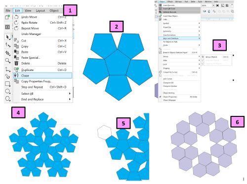
In creating the first hexagon, I sized it so that it was a similar size as an outer side of a pentagon. Screenshot 5 shows this. I fitted numerous hexagons into a snowflake-like shape as shown in Screenshot 6, but this proved to be pointless as the shapes did not align. I decided to look at the bucky ball again and reshape the hexagon snowflake. I decided that I needed a whole side of the hexagon snowflake to touch a full side of the pentagon snowflake. Screenshots 7-9 show the three versions of hexagon figures that I tested.
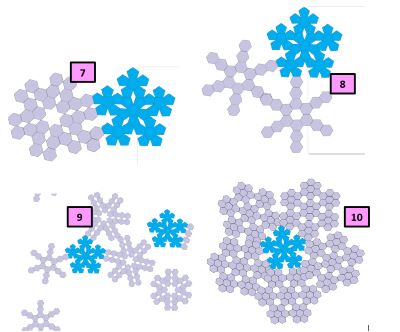
I had a lot of trouble determining what the right hexagon snowflake arrangement would fit on my pentagon snowflake. There always seemed to be either a large gap or an overalp in any arrangement. Then it dawned on me that the reason I could never make them fit was because I was trying to arrange a 3D design in a 2D format. This inspired me to try to build a bucky ball in another 3D CAD software.
Gimp Testing– An Addendum
After my global evaluator suggested it, I decided to try out Gimp. I downloaded the software (which was a lenghty download), and I could never actually open it. After several attempts, I decided to use a computer at the Charlotte Latin School Fab Lab that already had Gimp downloaded onto it.
Gimp
I decided to try Gimp by opening a new page and copying and pasting an image from online. I found my company (The Angelica Institute) logo since I know it well. There were several changes that could be made to the image. (I especially enjoyed reversing the image by seemingly flipping it around). The following images show some of the things I tested with the image in Gimp.
| Image | Description |
|---|---|
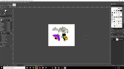
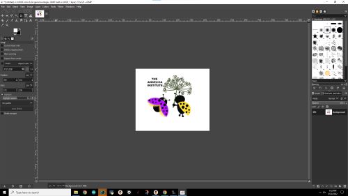 |
This shows the image of The Angelica Institute’s logo. Gimp brought the file in at the same size. |
 |
Here, I was able to blurr and clarify the image as well. I found it beneficial that I could modify one part of the image without modfiying the whole image. |
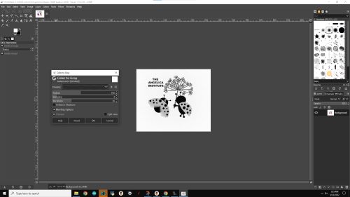 |
Gimp has the ability to turn the image into black and white– this is something that is also available in Inkscape and CorelDraw, but the shades of gray would have to be individually selected in those softwares. |
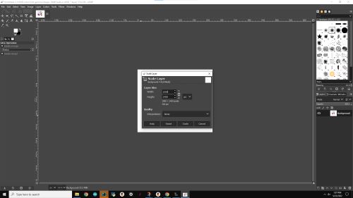 |
Gimp has the ability to change dimensions; one dimesion can be changed without changing the other dimension by selecting “None” at the dropdown menu next to “Interpolation”. If “None” is not selected, the dimensions will change together in ratio to each other. |
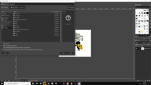 |
When files are saved in Gimp, they are saved as a .xcf file. |