4.0 Electronic Production- Making an In-Circuit Programmer
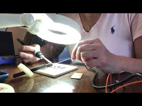
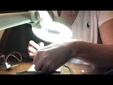
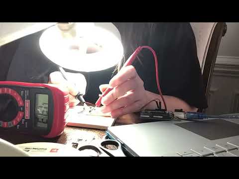
This week, our idividual assignment is to make an in-circuit programmer that includes a microcontroller. This assignment is one that I am nervous about because of the level of surface-mount soldering required. While I have practiced a lot with surface-mount soldering, my hands shake quite a bit at my age. To remedy this a couple of months ago, I designed a tweezer support that could hold LED’s and resistors in place while I soldered them onto a pre-made circuit board. After using the tweezer support with my curved, sharp tweezers, I realized I should modify that design to make it even better. The original tweezer support’s base was curved, and it sometimes slipped when I took my left hand off of it. So I re-designed it (in TinkerCAD– for ease and speed) to make a flattened base. I have attached the original Tweezer Support .stl file and the Revised Tweezer Support .stl file below.
Before starting this week, I did some research to understand the history of programming chips by reading the information at this page. AVR PROGRAMMING – ISP, JTAG, TPI, PDI AND UPDI.
ATTINY 412 Introduction
In January, the adult Fab Academy students at Charlotte Latin School met with Mr. Tom Dubick and Dr. Adam Harris to learn about how ATtiny 412 chips can be used in fabricating an “arduino” board. In that session, I completed the tasks with a lot of guidance from Dr. Harris, and I felt pretty lost in what was going on in each step. I also decided to watch Adam Harris’s video, FabUPDI setup and first use to program a AtTiny412 board], and read the information from this original site. In addition, I read Adam Harris’s article, Simple Fab-jtag2UPDI Board. I combined my notes from my original programming of the 412-chip PCB in January with the steps in Dr. Harris’s video and article. Before attempting a PCB with the ATMEGA, the following work explains what I did with the ATTINY 412 chips.
Work in January– main focus was to practice with using a manufactured Arduino as a programmer for the ATMEGA 412 chip. The following materials and steps outline (mainly) the work done on the coding side.
| Materials |
|---|
| 1, ATTINY4120SSFR Microchip |
| 1, (Manufactured) Arduino Uno |
| 1, Adafruit (8-pin Header) (with straight male pins) |
| 1, 4.7 k-Ohm Resistor |
| 1, Breadboard |
| 1, 5mm Blue LED |
| 1, Adafruit (8-holed) Breakout Board |
| Male-Male Jumper Wires (black–or cool color– for “neutral”/ground, and red– or hot color– for VCC [Voltage Common Collector] + additional colors) |
| HARDWARE ASSEMBLY |
|---|
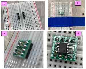
| 1) Cut 8-pin header in half so that two 4-pin headers result. Place the two 4-pin headers on opposing sides of the breadboard as shown in Screenshot 1 (below). |
| 2) Place breakout board onto two 4-pin headers in breadboard and solder it to the headers (shown in Screenshots 2 and 3). |
| Hardware Assembly (continued) |
|---|
| 3) Solder the ATTINY412 microchop into the center position on the breakout board (shown in Screenshot 4 above). |
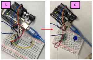
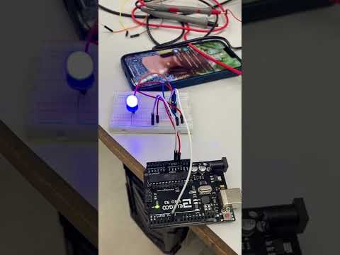
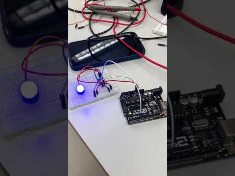
| 4) Wire the manufactured Arduino Uno to the breadboard using male-male jumper wires, and add the 5mm blue LED into the circuit (as show in Screenshots 5 and 6 below). |
| SOFTWARE COMPILATION |
|---|
| 5) Download most recent version of the Arduino IDE onto computer. |
| 6) Obtain a manufactured Arduino board (that will serve as a UPDI [Unified Program and Debug Interface] programmer). |
| 7) To begin adding the Arduino board manager go to Tools –> Boards –> Boards Manager in the Arduino IDE. |
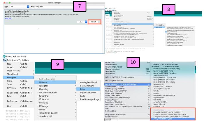
| 8) In the “Search” window, type in “MegaTinyCore” and hit “Enter”. Select “megaTinyCore by Spence Konde” by clicking on “Install” (as shown in Screenshot 7 below). |
| Software Compilation (continued) |
|---|
| 9) Download the “jtag2updi .zip” file. Extract it, and add it to the Arduino IDE by clicking on Sketch –> Include Library–> Include .ZIP Library. |
| 10) Install the most-recent version of the “Official Arduino megaAVR boards” package. |
| 11) Make sure that– under Tools –> Boards– that the ATTINY boards indeed now appear. (See Screenshot 8.) |
| 12) Open the “jtag2updi” code and load it onto the manufactured Ardnuino Uno. (This action converts it into a UPDI programmer.) |
| 13) With the whole apparatus (breadboard with LED and ATTINY chip and the manufactured Arduino Uno) connected to a computer via USB cable, open the example “Blink.ino” file in the Ardunio IDE. (For me, this file was located in the Arduino App under File –> Examples –> Built-In Examples –> Basics 0.1 –> Blink). This is shown in Screenshot9. |
| 14) Change the “Builtin LED” to pin “0” in the Blink.ino code, and select the “Board” to be the ATTiny. (See Screenshot 10 above). |
MY EXPERIENCE WITH THESE MATERIALS/STEPS
When I followed the above procedure, and I did run into some difficulties. I went to this site to download the jtagtupdi .zip file. (See Screenshot 11 below).
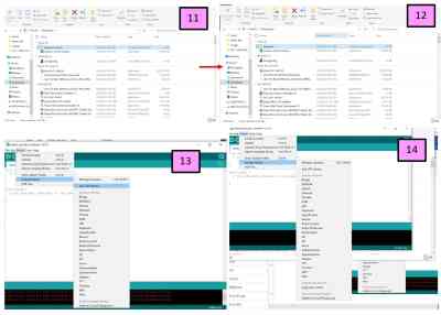
It appeared to download correctly, and I was instructed to rename the file without the word “master” in it (seen in Screenshot 12). I then added the .zip file to the library in the Ardunio IDE (as shown in Screenshots 13 and 14).
Although I had downloaded the jtag2updi file (shown in the downloads folder in Screenshot 15 below), it was not appearing when I tried to select it as the programmer (Screenshot 16). After many attempts, I was eventually able to get the jtag2updi option to show up. I opened the jtag2updi.ino file in the Arduino IDE (as shown in Screenshot 17), and uploaded this code to the Arduino Uno (telling it to now be a “programmer”). I then closed this file. Now it was time to upload the Blink.ino onto the ATTINY412 Microchip. Before doing this, I had to change the “Builtin LED” to pin “0”, and I selected the “Board” to be the ATTinyATTINY412 (as shown in Screenshot 18).
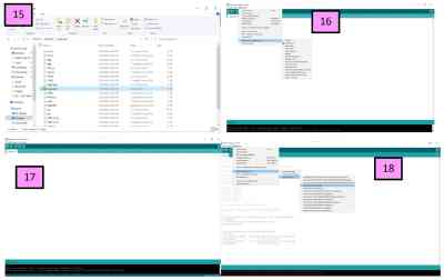
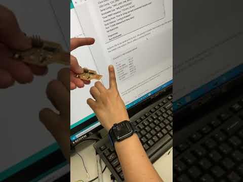
Next, on the Blink.ino file, I selected the “jtag2updi” to be the programmer. (See screenshot 19 below). I hit the upload button to send the code to the ATTINY412 chip, but I got an error message (shown in Screenshot 20). I struggled with this error for about ten minutes. Others in the group had also gotten the error message, and their LED’s still began to blink properly. I had hoped mine would do the same, but nothing changed as I countinued to repeat the process. I decided to switch my Arduino with a new board (the one used by colleague, Nidhie Dhiman that we knew was working). I did not get the same error message, but the LED still did not blink. Screenshot 21 shows this. When Nidhie Dhiman’s Arduino board did not work, I started to examine my soldering work. It appeared that one of the legs on the ATTINY412 chip was not touching the breakout board. I went to solder it again, and while I was doing this, I performed tests with a multimeter on the chip. Screenshot 22 shows that the chip was indeed getting the proper voltage.
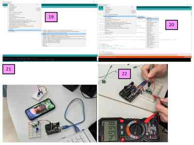
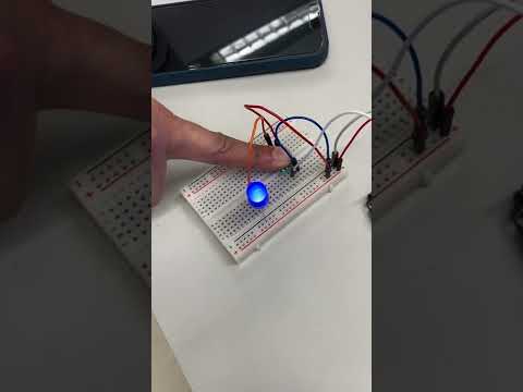
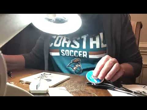
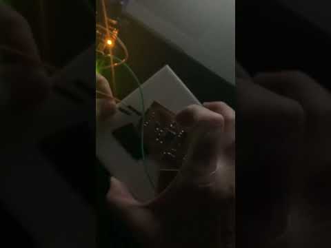
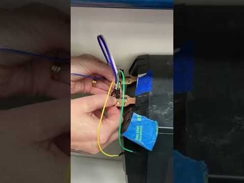
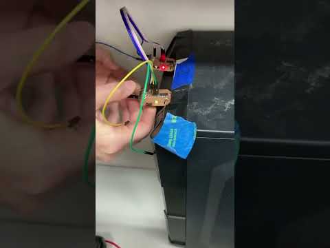
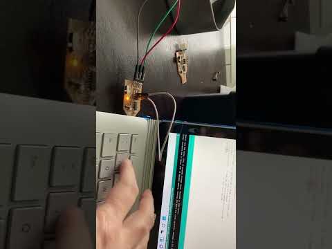
After testing the chip, I plugged the circuit in once again to Nidhie Dhiman’s Arduino; the LED did not blink. Very frustrated at this point, I began testing the voltage in other positions of the chip (as shown in Screenshots 23 and 24). Nidhie Dhiman pushed down on my ATTINY 412 chip, and the LED lit up, but it did not blink. (The short video below shows this). When testing the voltage under the VCC and GRND pins running through the breakout board, it showed there was not enought voltage.
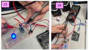
| Pushing On the ATTINY412 Chip | Blink Code Working | Modified Blink Code Working |
|---|---|---|
 |
 |
 |
ATTINY 412 Blinky (More Complex PCB)
| Materials |
|---|
| 1, ATTINY412-SSFR Microchip |
| 1, Yellow Surface-Mount LED |
| 1, 499-Ohm Resistor |
| 1, 4.9 k-Ohm Resistor |
| 1, Adafruit 6-pin (90 degree) Header with straight male pins |
| 1, 1 uF Capacitor |
| Jumper Wires (male-female) |
| Hardware Assembly |
|---|
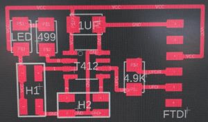
| 1) Download Eagle file from Dr. Adam Harris’s site. |
| 2) Using the workflow outlined by our group and a milling machine, mill the PCB. |
| 3) Tape the PCB down onto a ceramic tile. |
| 4) Solder the ATTINY412 Michrochip into the center. |
| 5) Solder 6-pin (90 degree) header to PCB. |
| 6) Solder the remaining four components. |
| PROGRAMMING THE ATTINY412 CHIP |
|---|
| 7) Using the same manufactured Arduino with the jtag2UPDI code already loaded onto it, use a “cool-colored” male-female jumper wire to connect the GRND on the Arduino to the first pin on the stuffed PCB. |
| 8) Connect the third pin to the 5V pin on the manufactured Arduino (using a “hot-colored” male to female jumper wire). |
| 9) Connect the second pin to pin 6 on the manufactured Arduino. (Note: This is the pin between the GRND and the 5V pin). |
| 10) Open the Blink.ino (Arduino) file on a computer and connect the Arduino to the computer using a USB cable. |
| 11) Change the “Builtin LED” to pin “6” in the Blink.ino code. Select the “Board” to be the ATTiny and the Programmer to be jtag2updi. |
MY EXPERIENCE WITH THESE MATERIALS/STEPS
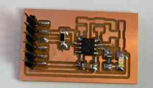
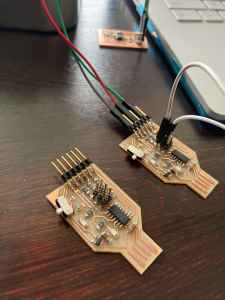
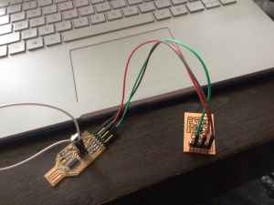
With the previous experience of creating and programming the ATTINY412 chip (written about in the introduction above), I decided to challenge myself this week and use a brand new manufactured Arduino board (rather than using the one that already had the jtag2updi code loaded onto it). I soldered all of the components onto the PCB, and I thought I had done a good job. The image below shows my stuffed board.
I went to program this PCB by following the steps carried out with the ATTINY chip on a breadboard, and I was successful in loading the code onto the ATTINY412 chip (since the code successfully uploaded and I saw the “TX and RX” LED’s light up). However, the LED on the PCB did not blink or light at all. I grabbed a multimeter and began testing all of the pins on the ATTINY chip first. They all showed they were receiving 5V.
Tom Dubick suggested that I now do a conductivity test on the other components on the PCB. When I performed the conductivity test on the LED and the resisitor closest to it, I found that they were not receiving 5V. I inspected the soldering work I had done on the PCB, and fellow classmate and colleage– Scott Moulton– looked closely at it too with magnifiers. He pointed out that the resistor by the LED was not touching the PCB at all. I quickly added more solder to this area, and connected it once again to the manufactured and pre-programmed Arduino board.
This time, I inadvertently reversed the GRND and 5V jumper wires on the PCB. I immediately got an error message on my computer stating that the USB port had been overloaded. I quickly unplugged the USB cord that was connecting the arduino to the computer, and I plugged it back in again. (NOTE: I plugged the USB cord into the same port as before). The LED was not blinking, and I was feeling pretty frustrated at this point. Tom Dubick came over and started to help me once again to perform continuity tests on all areas of the PCB. I added more solder to one of the header pins, and I tried plugging the stuffed PCB in again to the computer. This is when I realized I should try the other USB port on my laptop.
I plugged the stuffed PCB and Arduino board into the other USB port on my computer, uploaded the code, and IT WORKED!
ATTINY 412 MVP (Minimally Viable Programmer/Blinky)
| Materials |
|---|
| 1, ATTINY412-SSFR Microchip |
| 1, Red Surface-Mount LED |
| 1, 1uf Capacitor |
| 1, 499-Ohm Resistor |
| 1, Adafruit 3-pin Header with straight male pins |
| Jumper Wires (male-female) |
| HARDWARE ASSEMBLY |
|---|
| 1) Download the Eagle MVP file provided by Tom Dubick (found on Google Classroom). |
| 2) Using the workflow outlined by our group and a milling machine, mill the PCB. |
| 3) Tape the PCB down onto a ceramic tile. |
| 4) Solder the ATTINY412 Michrochip into the center. |
| 5) Solder the remaining four components. |
| PROGRAMMING THE ATTINY412 CHIP |
|---|
| 6) Using the same manufactured Arduino with the jtag2UPDI code already loaded onto it, use a “cool-colored” male-female jumper wire to connect the GRND on the Arduino to the first pin on the stuffed PCB. |
| 7) Connect the third pin to the 5V pin on the manufactured Arduino (using a “hot-colored” male to female jumper wire). |
| 8) Connect the middle/second pin to pin 6 on the manufactured Arduino. |
| 9) Open the Blink.ino (Arduino) file on a computer and connect the Arduino to the computer using a USB cable. |
| 10) Change the “Builtin LED” to pin “6” in the Blink.ino code. Select the “Board” to be the ATTiny and the Programmer to be jtag2updi. |
MY EXPERIENCE WITH THESE MATERIALS/STEPS
| First Attempt | Second Attempt |
|---|---|
 |
 |
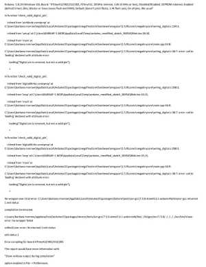
| When I went to program this stuffed PCB, the code indeed made it to the board as I saw the TX and RX lights light up. I wondered if I had soldered my LED and resistor in the reverse wrong position. So I asked my colleagues/classmates. Scott Moulton replied with a photo showing that mine was indeed reversed from what he had soldered. So I set out to stuff the second PCB that I had. | When I went to solder the components onto this second PCB, I saw– as I was taping it onto the ceramic tile– that the trace coming from the 5V pin was not attached at all and was sticking up. Realizing this board was not as cleanly milled as the prevuious one, I attempted to repair the uplifted trace by adding solder to it. This did seem to help, so I continued on with soldering the components onto it. This time, I soldered the LED and its adjoining resistor the same way that Scott Moulton did. Upon completion, I connected the sully stuffed PCB board to the pre-loaded Arduino board and connected all of it to a laptop with the blink code. When I uploaded the code, I got an error message (see table below). I switched USB ports and got a second error message (see table below). For the second error message, I realized I had changed the pin numbers– all except one. I then tried to upload the code again; this time, the code indeed made it from the computer to the Arduino programmer– again the TX and RX LEDS lit up on the Arduino. The LED on the PCB board still did not light up or blink. |
| |
| |
|
| First Error Message | Second Error Message |
|---|---|
 |
 |
At this point, I decided to mill another PCB board, stuff it and program it again. Write about this on Tuesday.
ATMEGA328 PCB
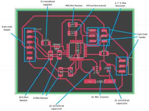
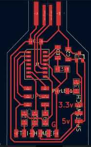
To be clear in my understanding of this circuit, I made a screenshot of Dr. Harris’s circuit design and labeled it. In examining it this closely, it actually helped me to understand and be better able to mentally “trace” the energy flow throughout the circuit.
 { align=center }
The following steps/screenshots/videos show my work with the ATMEGA328 chip and the PCB designed by Adam Harris.
| Materials |
|---|
| 1, ATMEGA328P-AU chip |
| 1, 16MHz crystal |
| 1, 6-pin header with male pins |
| 3, 3-pin header with straight mail pins |
| 1, 4.9-Ohm resistor (I actually used a 4.7-Ohm resistor.) |
| 1, 499-Ohm resistor |
| 1, 10K-Ohm resistor |
| 1, 0.1microfarad surface-mount capacitor |
| 2, 22 picofarad surface-mount capacitors |
| 1, Red LED (surface-mount) |
| 1, Manufactured Arduino Board (to serve as the UPDI programmer) |
| Hardware Assembly |
|---|
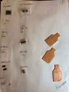
| 1) Download the Eagle file from Dr. Harris’s Fab Site. (In the Fab Lab at CLS, we assembled the parts for creating our Fab-jtag2UDPI Board. The screenshot below shows our parts that we gathered and labeled/taped on a piece of white printer paper.) |
| 2) Using the workflow outlined by our group and a milling machine, mill the PCB. |
| 3) Stuff the board (solder the materials (components) into their appropriate place on the board). Note: We did not have any “reset” buttons in the lab, so we decided we would solder a wire in its place and cut the wire after the board has been programmed. |
| 3) Obtain a manufactured Arduino board (that will serve as the UPDI [Unified Program and Debug Interface] programmer) This board is pre-programmed. Open the example “Blink.ino” file. For me, this file was located in the Arduino App under File –> Examples –> Built-In Examples –> Basics 0.1 –> Blink. |
MY EXPERIENCE WITH THESE MATERIALS/STEPS
| Stuffing the PCB | Troubleshooting (Testing Voltages Across Components) |
|---|---|
 |
 |
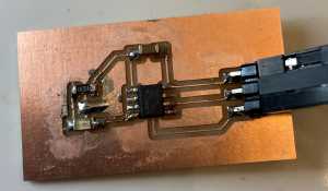
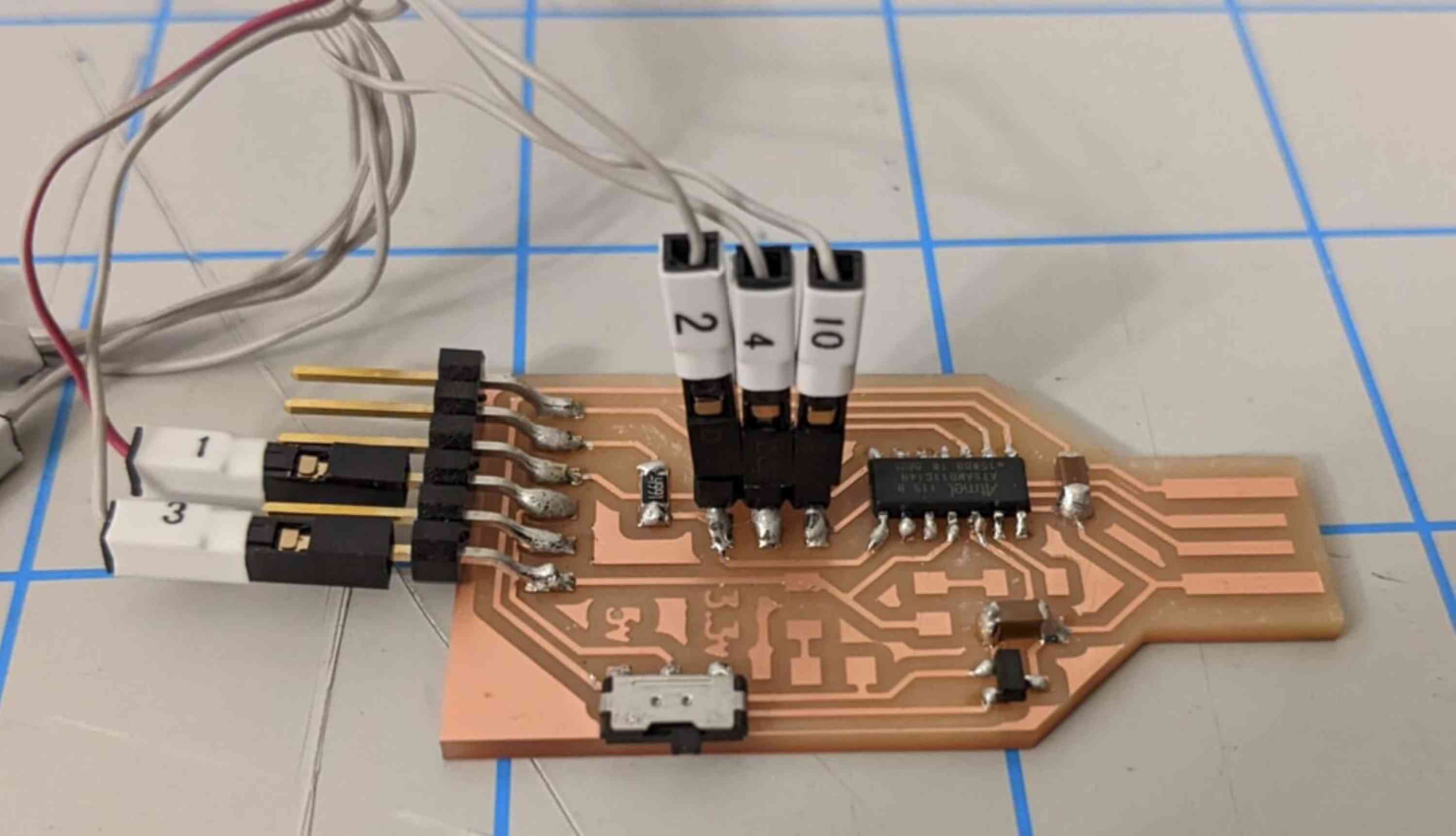
The image below shows my final, stuffed ATMEGA328 PCB.
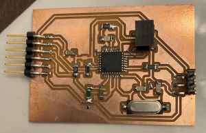
In stuffing this PCB, I was very proud of the soldering I was doing; I have definitely improved. Although the legs on the ATMEGA 328 chip are MUCH closer together, and there are four times as many legs than the ATTINY 412 chip, I learned how to solder this chip using the “swipe or drag” method as shown in SMD Soldering Tutorial - an introduction to drag soldering (beginners electronics). It was difficult in determining which direction the red LED should be oriented, but Scott Moulton and Nidhie Dhiman has sent photos of their lit-up LED.
When I connected the ATMEGA 312 PCB to the pre-programmed Arduino, the LED did not light. I was reminded that Adam Harris had told us that the LED would be very dim at first, and Scott Moulton told me his was dim for about 15-20 seconds. After waiting, the LED never did light up. I have had issues with one of my two USB ports on my laptop, and I tried the other port. When I did this, my laptop did not even register or show that the USB ports were being used. I swapped out the Arduino board for a brand new one, and it did not light up either. I restarted my laptop in the hope this would fix the problem. The built-in LED on the Arduino board was not even lighting, which meant no power was going to it. Restarting the laptop did not fix it; the same thing happened. Feeling completely defeated, it was late at night, and I decided to go to bed.
When I started working again the next morning, I did an Internet search to see how to remedy ports not working on Windows laptop. I found this site, and it suggested that the drivers might need to be reinstalled. I watched Fix USB Ports Not Working in Windows 10, and it had me look into “USB” on the “Device Manager” to see if there was an error message there. Going back to the original article (mentioned above) it suggested that I look for updates on my laptop. I did this, and there was an update for Windows 11. I began the Windows 11 update and restarted my laptop.
When it was rebooted, I again plugged in the pre-programmed Arduino board. The computer made the sound acknowledging the presence of something plugged into the USB ports. However, nothing showed up on the computer to show it there was a USB port being used. The built-in LED on the Arduino board was lit up, and I made the decision to continue to troubleshoot that issue at a later time.
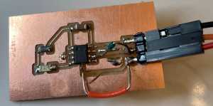
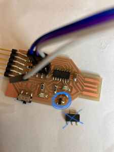
As I continued to troubleshoot the problem of the ATMEGA 328 board not powering up, I decided to check the voltages across all of the components on the stuffed board. When I did this, I found that all of the components had proper voltages. I used this image as a guide along with the image at the top of this page. However, when I traced energy to the chip, I found that one of the legs (the fourth one on the side near the red LED) was not functioning properly. I inspected this leg closely, and I could see that the connection is not good– there was not enough solder. See the circled area in the image below. The video shows me testing the stuffed ATMEGA 328.
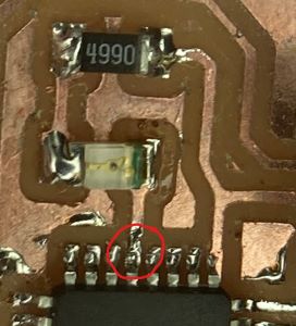

On Tuesday afternoon (February 22), I viewed my stuffed board under the microscope, and indeed, the 4th and 8th pins near the LED had no solder on them. The 8th pin didn’t really matter at that point, but the 4th pin was the GRND pin, and it is critical. I added solder to both pins– thankfully with no solder bridges. I went to power up the board, and the LED still did not light. I decided to solder/stuff another ATMEGA328 board, and I began pulling all of the materials out of the electrical drawers in the Fab Lab.
Soldering the components onto the second ATMEGA328 did not go well. I soldered the chip on first, and my “drag method” did not go well. I had solder bridges on literally all four sides of the ATMEGA chip. After about 30 minutes, I was able to remove the solder bridges using the desoldering braid/wick. Adding more solder to the pins the second time around was easier as I “brushed” the pins to get enough solder onto them.
I continued to solder the remaining components onto the PCB. When I went and plugged it in, the LED did not power up. At this point, I began to collect materials to stuff a third ATMEGA328 board. As I was starting to collect more components, classmate, Avery Horvath, walked into the Fab Lab to work. Avery was confused why her stuffed board was not working. She had checked every component (as I had done), and she was getting correct voltages– EXCEPT in the area above the chip and near the LED (JUST LIKE MY BOARD!). As we discussed all of the tests we had done, Avery and I examined each other’s stuffed boards. Colleague (and electrical and computer engineer), Adam Durrett was nearby, and we asked him for help. Adam realized two things: 1) that we should have been connecting pin 6 on the Arduino to the SCK pin (located just to the right of the LED (middle pin on left – of the 2 x 3 pins); and 2) I was not uploading the code properly. I was reversing the “Board” and the “Programmer”. Once these were remedied, I uploaded the Blink.ino code again, and the LED started to blink! The video below shows both of my boards blinking… one second on, two seconds off.
Knowing that my board was working, Avery and I decided to connect her stuffed board to my Arduino. Avery’s LED began blinking very brightly, and her board worked perfectly. I connected my second board (the one I most-recently stuffed), and its LED also blinked. Neither of my LED’s blinked as brightly as Avery’s, but this was a huge step in the right direction. Now all I had to do was programm the two stuffed ATMEGA328 PCB’s to now be the programmer.
ADDENDUM I am adding this to my write-up as an addendum because what I thought was a working stuffed PCB for the ATMEGA328 chip, was–actually NOT working. I thought that the only remaining thing I had to do was program something else with it.
As I came into the Fab Lab on Wednesday, February 23, I was under the impression that my manufactured Arduino had already been converted into a programmer, and I was ready to transfer code to the new target– the stuffed ATMEGA328 PCB’s . What was really happening was the manufatured Arduino was really just running the blink code for the ATMEGA328 PCB, telling it to blink. I had read Adam Harris’s article numerous times, and I knew I needed to obtain an FTDI cable in order to complete the next steps. As I read the instructions and downloaded software to do this, I was too afraid to actually carry out Dr. Harris’s steps. Knowing that he was coming in to meet with us in person later that day, I decided to “play it safe” and wait for him. In the meantime, Tom Dubick suggested that I upload the bootloader to the manufactured Arduino. It did not work. We tried the same thing using my second stuffed ATMEGA328 PCB, and it also failed.
That afternoon, I milled and stuffed two more ATMEGA328 PCB’s to have on hand when Dr. Harris arrived. I re-watched Adam Harris’s two videos, Programming the UPDI firmware then using the Fab jtag2UPDI I designed and FabUPDI setup and first use to program a AtTiny412 board, and I also re-read Adam Harris’s article/writeup. One writeup, Arduino as ISP and Arduino Bootloaders really helped me to understand the roles in the “Programmer-Target” relationship, and how to change those roles.
When Dr. Harris arrived, and we began to examine the (now FOUR stuffed ATMEGA 328 PCB’s), we realized that the 0-Ohm resistors that were meant to be “jumpers” were both black and green in color on all four of my stuffed PCB’s. Questioning this, Dr. Harris did a multimeter test on them, and he found that the black ones were actually producing 5-V readings, but the green ones were correct. Someone in the lab had mixed the two resistors in the same bin. Of the four boards, the first two that I had stuffed were safe to use as the last two had incorrect, black, 5V resistors on them. Dr. Harris patiently went through each part of the board, and we were able to successfully load the needed bootloader onto Board 1. However, I had to go back and add solder to that 8th leg on the chip near the LED, and I also had to add solder to the 0-Ohm resistor connected to the gorund pin. We spent the next hour trying to upload the needed jtag2updi code onto the board with no success. Dr. Harris began to work on Avery’s stuffed ATMEGA PCB, and similarly, he was able to get the bootloader onto the board, but nothing else.
As Avery and I worked with Dr. Harris, Nidhie and Scott were working with Tom Dubick. Four out of five of us were able to get the bootloader onto the board, but we could not go further. It was at this time that the decision was made to switch to using the SAMD11 PCB’S. Dr. Harris instructed us to use the SAMD11 boards that were known to be functioning properly as programmers to get ours working . (The Charlotte Latin students had many that were indeed working properly, and Dr. Harris also left one of his with us).
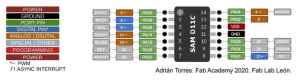
SAMD11 PCB
| Materials |
|---|
| 1, SAMD11C14IC13 (Chip) |
| 1, 3.3v LDO regulator |
| 1, 2x3 pin header |
| 2, uF Capacitors (Surface Mount) |
| 6-pin SMD male horizontal header FTDIPwrLED1 |
| 2, Red, Surface Mount LED’s |
| 1 switch (or 3-pin vertical header) |
| 2, 330 Ohm Resistors |
| 1, 4.99 k-Ohm Resistor |
| 1, 1.2 k-Ohm Resistor |
| 1, 0 Ohm jumper |
| Hardware Aseembly |
|---|
| 1) Download .gbr file from Dr. Adam Harris’s site. |
| 2) Using the workflow outlined by our group and a milling machine, mill the PCB. |
| 3) Stuff the board (solder the materials (components) into their appropriate place on the board). |
| 4) Obtain an Atmel ICE programmer and a windows computer. |
| 5) Download the Windows version of edbg (debugging software). |
| 6) Download the binary of the firmware. |
| 7) Connect up the atmel ICE programmer to the SAMD boardn using the diagram below. |
| Pinout | Pin Usage |
|---|---|
 |
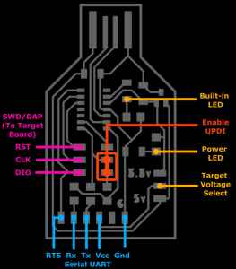 |
| Programming the SAMD (continued) |
|---|
| 8)Download the windows version of edbg firmware. |
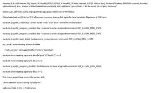
| 9) In the Windows command prompt, type “cd ___” (to the location) you downloaded the files to and type this in the command prompt: “edbg-windows-r24.exe -bpv -e -t samd11 -f sam_ba_Generic_D11C14A_SAMD11C14A.bin”. |
| 10) In the arduino software, go to File→Preferences and click the icon next to “Additional Boards”. Copy and paste this URL address: “https://www.mattairtech.com/software/arduino/package_MattairTech_index.json”. |
| 11) To install the SAMD boards in Arduino, go to Tools→Boards→Board manager. |
| 12) earch for “SAMD” and install the “MattairTech” one only. |
| Programming the SAMD (continued) |
|---|
| 13) Choose a pin to connect an LED to a breadboard. |
| 14) In the Arduino IDE, select “INTERNAL_USB_CALIBRATED_OSCILLATOR” when plugged into the USB port for power and “INTERNAL_OSCILLATOR” when you want it powered without a USB port. |
| 15) Follow the instructions for Arduino code on Dr. Harris’s webpage. |
| 16) Get an ATTiny Blinky board to blink using a “Blink.ino code” from the “Exmaples” in Arduino IDE. Be sure to change “Builtin LED” to pin 0. |
| 17) in Arduino, change the chip to the aATTiny 412. |
| 18) Change the “programmer” to “SerialUPDI – SLOW: 57600 baud, any platform…”. |
| 19) Wire the SAMD board (paying close attention to the jumper wires in the images) on Dr. Harris’s webpage (instructions for Arduino code on Dr. Harris’s webpage. |
MY EXPERIENCE WITH THESE MATERIALS/STEPS
Once the decision was made to switch all of us to using the SAMD11 Board instead of the ATMEGA328, we worked together to pull the materials and mill the new needed PCB’s. This wound up taking much longer than anticipated because we could only mill one board at a time, and it required us to change the bit (and subsequently locate the tool three times) in each job. We tried using three different desktop milling machines in the Fab Lab, but in the end, we found that only one was doing it successfully. (We think the beds were not level after so much use). The machine I was using seemed to produce the best-looking boards. After about two hours, we all had enough PCB’s to stuff two boards each. However, the last PCB (one of mine) looked bad to me. When Dr. Harris and I examined it under the microscope, he showed me that much of the “messy-appearing” copper was just flakes that could be removed with sanding. The image below shows the materials as I left the Fab Lab.
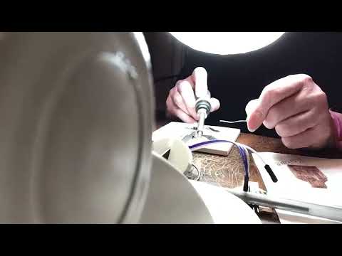
Building, stuffing and programming the SAMD went much better than the ATMEGA. I left the Fab Lab around 11:15 pm that night. I began stuffing my two SAMD11 PCB’s when I got home, but first I had to clean up that last one I milled. I remembered that I had a special fingernail filing board–a SEACRET Buffing Block, and I decided to try it on the both of my PCB’s before adding components to them. I found out that this buffing block worked BEAUTIFULLY on the PCB’s, and it didn’t scratch it at all (like fine sand paper did on previous boards). I was so excited about this buffing block that I shared it with classmate, Charlie Horvath. The following videos show me stuffing both of the SAMD11 PCB’s (at the same time).
As I was finishing up the boards, I realized that we had pulled the 3.3-V regulators were not correct, and that I would have to wait until Thursday morning to finish.
At that point, I read Dr. Harris’s SAMD11C Milti-use Board with the hope of understanding what I would need to do after I added the correct 3.3V regulators in the morning.
When I arrived at the Fab Lab the next morning, I quickly soldered on the proper 3.3V regulators before teaching my classes. After teaching, colleague/classmate–Nidhie Dhiman–was also ready to start programming her stuffed PCB, and we decided to work through it together. We were able to successfully convert all three of the stuffed SAMD11 PCB’s that we had with us. (We used the Command Prompt and the other functioning SAMD11 baords that we had).
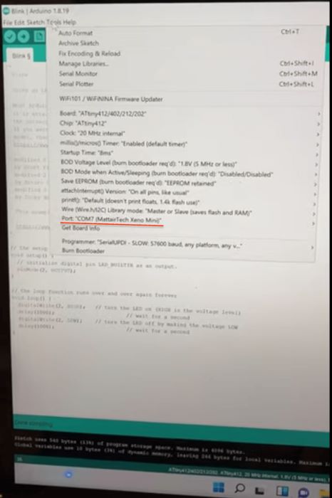
At this point, we were both elated. Colleague, Adam Durrett tested his SAMD board, and it did not work. Since I had two working programmers, I gave him one that he could “play around with”. To prove we were success, we tried to upload an Arduino blink code to our boards. Nidhie was able to upload it onto hers, but I was not. When we plugged my SAMD11 into the USB ports, the “COM7Mattain” port we had been using did not appear for mine. I had to ask Adam Durrett for the SAMD11 board back, and at this point, I had to leave to drive home where I planned to try again.
When I got home, I went to plug in my now SAMD11 PROGRAMMER, and the USB ports were again not working on my laptop. I restarted the laptop, and they still were not functioning. I spent a couple of hours working to get them functioning, and I eventually gave up for the evening. In the Arduino IDE, the correct COM port was still not appearing.
The next morning, I woke up with pink eye, and I wasn’t able to go to work. I was really hoping to get Tom Dubick’s help, but that was not going to happen. I read through Dr. Harris’s article again, and the next thing I did was update my laptop with Windows 11. This update took a really long time! But the good news was that the ports were now working properly, as the drivers were likely fixed during the update. In the Arduino IDE, I was still not getting the needed COM port. I realized I needed to install the two “json” files (one with the ATTINY and one with the SAMD11). Once I did this, I was back on track with the instructions in Dr. Harris’s article, and the correct COM port was indeed there. I had a small hiccup with wiring the SAMD11 board to my ATTINY Blinky board, but I was actually able to figure out that I was using the wring side of the 2 x 3 header.
This is a screenshot of my SAMD11C PCB being recognized by the COM Port of my laptop.
Milling PCB’s with Other Mill Milling Machines and Bantam Software
In preparation for my work with printed circuit boards this week, I decided to research other creative ways of making PCB’s. I found three videos that I found to be interesting (linked below).
TechXposed - Build Your Own Arduino…From Scratch!:
DIY PCB Ink Plotter using Arduino and GRBL CNC - Make PCB at home in few hours:
I was a little familiar with using the milling machines since I recently had my high school students mill dogtags and blocks of wax (to make chocolate molds). However, I had never milled a PCB on my own before. Colleague/classmate Nidhie Dhiman and I had worked together to mill Dr. Adam Harris’s Blinky board. It was in this session, thay I was able to follow Nidhie’s lead in how to use the Bantam software and determine the appropriate bits to use. In early February, Tom Dubick prepared us for this (electrical production) week in showing us how to mill, solder, stuff and verify the functionality of ATTINY412 and ATMEGA328 chips. The following steops show what I have learned in this process.
Using Milling Machines at Charlotte Latin School
This week, I learned how to mill PCB’s on Other Mill Milling Machines in the Charlotte Latin School Fab Lab. All of the PCB’s mentioned in this post were milled by me except for the ATTINY412 Blinky– designed by Adam Harris. As I learned to use the milling machines, I developed the following workflow in two parts: 1) Preparing Materials, and 2) Using Bantam Software. I showed this workflow to colleagues, Nidhie Dhiman and Scott Moulton, and we all decided we would use this workflow on our group page.
Preparing Materials for Milling (on Other Mill)
- Download .gbr file for milling.
- Ensure the other mill is clean and free of debris. Using shop vacuum, suction debris from the metal bed. (Vacuum out any materials leftover from previous use).
- Wipe the bed with alcohol-saturated paper towel.
- Turn on Other Mill milling machine.
- Open Bantam Tools software on computer.
- Obtain new prototype board.
- Add (double-sided) Nitto tape to back of prototype milling board (enough to nearly cover entire surface).
- Use callipers to measure the length, width and thickness of the prototyping milling board with the tape.
- Remove plexiglass safety window(s). (Removing front and both side safety windows provides ample room for both hands inside machine.
- Remove paper backing from (double-sided) Nitto tape and affix prototyping board to the metal bed. Be sure to place the prototyping board snuggly in the front left corner.
- Press firmly on prototyping board so that the entire board comes into contact with the metal bed.
- Firmly press and slide the green plastic “scraper” over the entire surface of the prototyping board to ensure proper adhesion to metal bed.
- Obtain proper bits to be used. (We used a 5-degree [0.005] and 1/32 bits to mill our PCB’s). (Use flat end mills for cutting 2D shapes like circuit boards, flat-sided 3D shapes, and for detail work. Use ball end mills for cutting curves and 3D shapes into woods, waxes, and plastics. Use engraving bits for fine detail work.)
- Insert (and start job with the higher detail) bit into the milling machine.
- Make sure blue rubber covering is on the sharp end of the bit or that the square foam piece is resting under the bit before removing/changing it. (If the bit is dropped, these will prevent the bit from chipping).
- Use small wrenches (one in each hand) to turn the collets in opposing motions to remove/change bits.
- When tightening collets after swapping out the bit, give them one more moderately hard twist to finish.Do not tighten the collet too much, and NEVER fully tighten the collet when there is no bit in it.
- Place your wrenches on top of the milling machine. There are magnetic pockets on the top of the milling machine to keep the wrenches handy while you’re working.
- Put the safety windows back into place.
Configuring in Bantam Tools Desktop Milling Machine Software
The Bantam Tools Desktop Milling Machine Software controls the Othermill. Load PCB (or other) design files into the Bantam Tools software and the program will determine the optimal toolpaths to complete the milling project. Bantam Tools Desktop Milling Machine Software supports the following file types: Vectors (.svg), EAGLE (.brd), Gerbers, and G-code (.nc, .tap, .gcode).
- Open Bantam Software, click File > Open or the Open Files button on the right side of the the software window.
- Navigate to the directory that contains your Gerber files.
- Open the desired Gerber file.
- Select tool (end mill or engraving bit) by selecting “change”.
- Choose tool from “New Tool” dropdown choices. -Install tool by loosening collet and replacing tool. (This may have already been done when preparing the materials for milling).
- Click “continue”.
- Home the mill. Be sure that the installed tool/bit touches the right side of the metal plate, NOT the prototyping board or material being cut.
- Select “Material”– either generic or FR-1. (For milling our PCB’s select “Single-sided FR-1).
- Also under “Material” –> “Size”, enter dimensions in the X, Y, and Z values that were gained using callipers above.
- Under “Placement”, make sure “at left bracket origin” is selected.
- Where the .gbr file is visible on the right-hand side (under the “Open” button), there is a right-facing carrot. Click on this carrot so that a dropdown menu appears.
- Click on the carrot next to “Placement”, and enter the values of where the milling will actually begin. (For our PCB’s, we used an X value of 4 and a Y value of 4.)
- Slide the button on “Parts to Mill” to the right so that “top” is selected.
- Be sure that “Traces”, “Holes”, and “Outline” are ALL selected. NOTE: To make sure these are selected, they must NOT be “lit up” in Bantam Tools Software.
- Under “Milling Tools”, select all of the bits that will be used in fully milling your design. (For our PCB’s, we used the 1/32 Flat End Mill and the 0.005 bit).
- Once all information has been entered, you will not use the tools in the right side of the screen until you start the job.
- Click on Bit Breaker menu choice in upper left corner.
- Make sure the metal clip is clamped onto the prototyping board, and allow the machine to probe material thickness. It is important to use the Bit Breaker tool over every area of the board that you plan to use.
- Replace metal clip into original position on the upper front portion of the metal bed.
- If milling multiple PCB’s, use the “Open” button for each individual (potentially duplicated) file, and repeat steps 5-16 making sure to adjust the “X” and “Y” location values for each one.
- Once all of the information has been entered, click on “Mill All Visible…” in the lower right corner.
- Bantam Desktop Milling Machine Software will alert/prompt you when the tool/bit should be changed.
- If the machine begins to falter, or to run poorly or inconsistently, stop the machine by pushing the large red emergency stop button on the lower right side. You can run the job again, but adjust the settings under the “Advanced” button/carrot based on the reason for the failure/inconsisten cut.
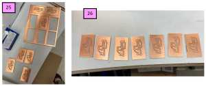
One morning before school the previous week, colleague/classmate, Nidhie Dhiman and I began milling Tom Dubick’s newly created minimally viable programmer (MVP) PCB design. My students were cutting dogtags that week, and this was my first exposure to Bantam software. With Nidhie (who had more experience with the machines and software), I was able to learn about cutting multiple PCB’s in one job. This included changing the positioning (X and Y values), entering bit information, and making sure “Traces”, “Holes” and “Outlines” was selected properly for each file we opened in the software. The screenshots below show the seven MVP PCB’s that we cut that morning.
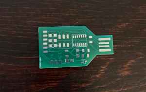
This site shows how to order production quality PCB’s. Nidhie Dhiman sent our SAMD11 PCB to be professionally manufactured. The image below shows the professionally manufactured SAMD11 PCB.
To see my contributions during the group work project, please visit Group Project-Electronic Production.
To see the write-up of group work, please visit Electronics Production-In-House PCB Process.
File Links Tweezer Support Revised Tweezer Support