15.0 Interfacing
This week’s individual assignment is to write an application that interfaces a user with anminput &/or output device that you made.
Preparing
In order to prepare for this week’s assignment, Tom Dubick shared the following video tutorials with all Charlotte Latin School Fab Lab students.
Processing 1– This video was made by Tom Dubick, and I uploaded it to my YouTube account (as an unlisted video).
ProcessingVariableRandom– This video was made by Tom Dubick, and I uploaded it to my YouTube account (as an unlisted video).
Processing Loops– This video was made by Tom Dubick, and I uploaded it to my YouTube account (as an unlisted video).
Conditional Statements in Processing
After watching Tom Dubick’s videos, I wanted to do another search to confirm how I could take an already-compiled Processing code and use it with Arduino. I found Sparkfun’s Connecting Arduino to Processing.
I have been really wanting to get my PIR sensor functioning with my RGB LED, and I thought this week might be a good time to make that happen. I decided to do an Internet search to see if I could find code that had already been written in the Processing IDE, and I came across this site– Make Arduino and PIR motion sensor work in processing code with boolean….
I decided to try this code in Processing myself and see if I could modify it to use with my PIR sensor and my RGB LED PCB’s (from a couple of weeks ago). It was my plan to go from an Arduino code into Processing.
I did more research, and I found a former Fab Academy student’s page– Yuichi Tamiya– and this led me to the Adafruit NeoPixel site. Yuichi also led me to read this site.
In a meeting with Dr. Adam Harris, I discussed my plan, and I decided to do some more research about using neopixels with processing. Colleague and classmate–Nidhie Dhiman– overheard me and mentioned that she was also planning to work with neopixels as well. Nidhie shared “LED ring in Arduino - How to make an interface in Processing IDE to select a color”. This site contained an Arduino code and a processing code that– I felt– would be a good starting place.
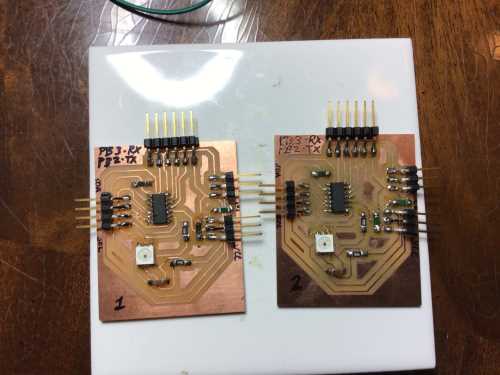
I went into the Charlotte Latin School Fab Lab and did a search for Adafruit Neopixel Ring, and I was able to obtain two rings that are described in the link above (one had 16 LEDs and the other 24). However, when I examined them closely, thy had been soldered before, and there was still solder and partial wire in the connection points. I attempted to remove the solder so that I could add new connectors, but as I did this, it seemed I was damaging the copper “pads”/rings.
![]()
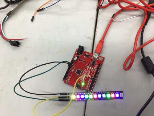
Very disappointed, I noticed a strand of NeoPixels on the soldering table left behind from one of my students. I decided to try this same code on a single 12-NeoPixel strand.
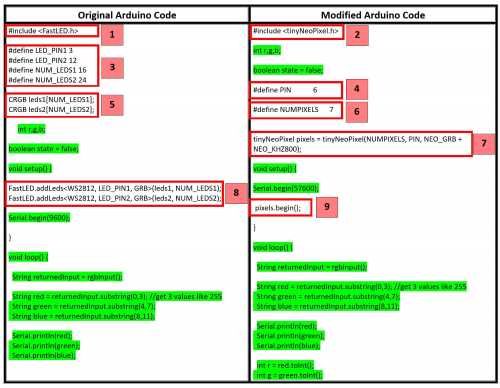
The first thing I needed to do was understand the Arduino code, and I began breaking it down and examining it with Dr. Harris. I felt that after I understood it, I could modify it for any of my ATTiny PCB’s that had available pins. The following images and table describe the differences (in red) between the code I found and modified. The green highlighted portions are shared lines of code.
| Code Section # | Description |
|---|---|
| 1 | This is the Arduino library used for the Adafruit Neopixel ring. |
| 2 | This is the tinyNeoPixel (WS2812) library for a strand of neopixels used with the megaTinyCore. This library replaces the FastLED library used by Adadfruit NeoPixel ring. |
| 3 | Two Adafruit Neopixel rings were intended to be used in this sketch. The first two lines here state which pins will be used on the Ardunino Uno and the last two lines show the number of neopixels are on each ring. |
| 4 | This line of code states the pin number that will be used on the ATTiny1614 chip. |
| 5 | These two lines declare the type of neopixels that will be used. |
| 6 | This line of code determines the number of neopixels in the strand being used. |
| 7 | These are the parameters identified in “tinyNeoPixel pixels” library. |
| 8 | These are the parameters identified in “FastLED” library. |
| 9 | This initializes the NeoPixel library. |
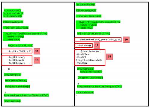
| 10 | This (pixels.Color) takes RGB values, from 0,0,0 up to 255,255,255 |
| 11 | This turns on all the LEDs on the ring to the selected color. |
| 12 | This sends the updated pixel color to the hardware. |
| 13 | These are commands in the FastLED library. |
| 14 | These end the commands (and close the brackets) in the loop. |
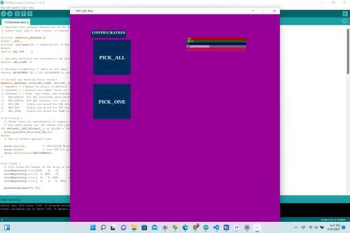
The site mentioned above–“LED ring in Arduino - How to make an interface in Processing IDE to select a color“– (from Nidhie Dhiman) also contained the code for Processing flexible software sketchbook (shown below).
ColorPicker cp;

void setup(){ //Same as setup in arduino

  size(900, 900);                          //Window size, (width, height)
  port = new Serial(this, "COM4", 9600);   //Change this to your port

  cp5 = new ControlP5(this);

  font = createFont ("Georgia Bold", 20);
  font2 = createFont ("Georgia Bold",15);

cp = cp5.addColorPicker("PICKER")
        .setPosition(500,100)
        .setColorValue(color(255,128,0,128))
        ;

Group configGroup = cp5.addGroup("CONFIGURATION")
    .setPosition(90,100)
    .setWidth(150)
    .setHeight(30)
    .setFont(font2)
    .setBackgroundColor(color(0,0))
  ;

  cp5.addButton("PICK_ALL")  // The button
    .setPosition(10, 10)     // x and y relative to the group
    .setSize(160, 150)       // (width, height)
    .setFont(font)
    .setGroup(configGroup)   // add it to the group
  ;

  cp5.addButton("PICK_ONE")  // The button
    .setPosition(10, 200)    // x and y relative to the group
    .setSize(160, 150)       // (width, height)
    .setFont(font)
    .setGroup(configGroup)   // add it to the group
  ;

}

void draw(){  //Same as loop in arduino

  background(150, 0 , 150); //Background colour of window (r, g, b) or (0 to 255)

}

public void controlEvent(ControlEvent c){

  if(c.isFrom(cp)){
    int r = int(c.getArrayValue(0));
    int g = int(c.getArrayValue(1));
    int b = int(c.getArrayValue(2));
    int a = int(c.getArrayValue(3));
    col = color(r,g,b,a);
  }
}

void keyPressed(){

  while(serialMonitor.available() > 0)
  {
    prompt = serialMonitor.readStringUntil (10);
  }

  println(keyCode);

  String sendColor = nf(int(red(col)),3) + "," + nf(int(green(col)),3) + "," + nf(int(blue(col)),3);

  println(sendColor);
  serialMonitor.write(sendColor);

}

void PICKER(){
  port.write('2');
}

void PICK_ALL(){

  port.write('t');

}

void PICK_ONE(){

  port.write('l');

}
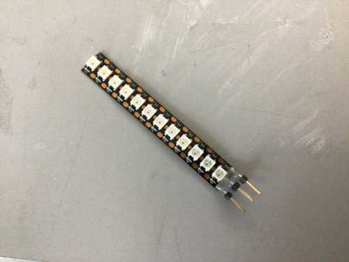
Before attempting to upload and test out these codes, I soldered male headers onto the end for easy connection to my PCB’s. (This was also a trick Nidhie Dhiman had shown me since she had been working heavily with NeoPixel strands).
I needed to wire the NeoPixel strand to an Arduino Uno to make sure that it was functioning properly. I used the RGBW STrand Test code in “Examples–>Adafruit NeoPixels–>RGBWStrandtest”. The
I copied and pasted the code (shown below) into the Arduino IDE. Since I was initially using an Arduino Uno, I was able to use the “already included” Adafruit_NeoPixel.h library.
// NeoPixel test program showing use of the WHITE channel for RGBW
// pixels only (won't look correct on regular RGB NeoPixel strips).

#include <Adafruit_NeoPixel.h>
#ifdef __AVR__
 #include <avr/power.h> // Required for 16 MHz Adafruit Trinket
#endif

// Which pin on the Arduino is connected to the NeoPixels?
// On a Trinket or Gemma we suggest changing this to 1:
#define LED_PIN     6

// How many NeoPixels are attached to the Arduino?
#define LED_COUNT  60

// NeoPixel brightness, 0 (min) to 255 (max)
#define BRIGHTNESS 50 // Set BRIGHTNESS to about 1/5 (max = 255)

// Declare our NeoPixel strip object:
Adafruit_NeoPixel strip(LED_COUNT, LED_PIN, NEO_GRBW + NEO_KHZ800);
// Argument 1 = Number of pixels in NeoPixel strip
// Argument 2 = Arduino pin number (most are valid)
// Argument 3 = Pixel type flags, add together as needed:
//   NEO_KHZ800  800 KHz bitstream (most NeoPixel products w/WS2812 LEDs)
//   NEO_KHZ400  400 KHz (classic 'v1' (not v2) FLORA pixels, WS2811 drivers)
//   NEO_GRB     Pixels are wired for GRB bitstream (most NeoPixel products)
//   NEO_RGB     Pixels are wired for RGB bitstream (v1 FLORA pixels, not v2)
//   NEO_RGBW    Pixels are wired for RGBW bitstream (NeoPixel RGBW products)

void setup() {
  // These lines are specifically to support the Adafruit Trinket 5V 16 MHz.
  // Any other board, you can remove this part (but no harm leaving it):
#if defined(__AVR_ATtiny85__) && (F_CPU == 16000000)
  clock_prescale_set(clock_div_1);
#endif
  // END of Trinket-specific code.

  strip.begin();           // INITIALIZE NeoPixel strip object (REQUIRED)
  strip.show();            // Turn OFF all pixels ASAP
  strip.setBrightness(BRIGHTNESS);
}

void loop() {
  // Fill along the length of the strip in various colors...
  colorWipe(strip.Color(255,   0,   0)     , 50); // Red
  colorWipe(strip.Color(  0, 255,   0)     , 50); // Green
  colorWipe(strip.Color(  0,   0, 255)     , 50); // Blue
  colorWipe(strip.Color(  0,   0,   0, 255), 50); // True white (not RGB white)

  whiteOverRainbow(75, 5);

  pulseWhite(5);

  rainbowFade2White(3, 3, 1);
}

// Fill strip pixels one after another with a color. Strip is NOT cleared
// first; anything there will be covered pixel by pixel. Pass in color
// (as a single 'packed' 32-bit value, which you can get by calling
// strip.Color(red, green, blue) as shown in the loop() function above),
// and a delay time (in milliseconds) between pixels.
void colorWipe(uint32_t color, int wait) {
  for(int i=0; i<strip.numPixels(); i++) { // For each pixel in strip...
    strip.setPixelColor(i, color);         //  Set pixel's color (in RAM)
    strip.show();                          //  Update strip to match
    delay(wait);                           //  Pause for a moment
  }
}

void whiteOverRainbow(int whiteSpeed, int whiteLength) {

  if(whiteLength >= strip.numPixels()) whiteLength = strip.numPixels() - 1;

  int      head          = whiteLength - 1;
  int      tail          = 0;
  int      loops         = 3;
  int      loopNum       = 0;
  uint32_t lastTime      = millis();
  uint32_t firstPixelHue = 0;

  for(;;) { // Repeat forever (or until a 'break' or 'return')
    for(int i=0; i<strip.numPixels(); i++) {  // For each pixel in strip...
      if(((i >= tail) && (i <= head)) ||      //  If between head & tail...
         ((tail > head) && ((i >= tail) || (i <= head)))) {
        strip.setPixelColor(i, strip.Color(0, 0, 0, 255)); // Set white
      } else {                                             // else set rainbow
        int pixelHue = firstPixelHue + (i * 65536L / strip.numPixels());
        strip.setPixelColor(i, strip.gamma32(strip.ColorHSV(pixelHue)));
      }
    }

    strip.show(); // Update strip with new contents
    // There's no delay here, it just runs full-tilt until the timer and
    // counter combination below runs out.

    firstPixelHue += 40; // Advance just a little along the color wheel

    if((millis() - lastTime) > whiteSpeed) { // Time to update head/tail?
      if(++head >= strip.numPixels()) {      // Advance head, wrap around
        head = 0;
        if(++loopNum >= loops) return;
      }
      if(++tail >= strip.numPixels()) {      // Advance tail, wrap around
        tail = 0;
      }
      lastTime = millis();                   // Save time of last movement
    }
  }
}

void pulseWhite(uint8_t wait) {
  for(int j=0; j<256; j++) { // Ramp up from 0 to 255
    // Fill entire strip with white at gamma-corrected brightness level 'j':
    strip.fill(strip.Color(0, 0, 0, strip.gamma8(j)));
    strip.show();
    delay(wait);
  }

  for(int j=255; j>=0; j--) { // Ramp down from 255 to 0
    strip.fill(strip.Color(0, 0, 0, strip.gamma8(j)));
    strip.show();
    delay(wait);
  }
}

void rainbowFade2White(int wait, int rainbowLoops, int whiteLoops) {
  int fadeVal=0, fadeMax=100;

  // Hue of first pixel runs 'rainbowLoops' complete loops through the color
  // wheel. Color wheel has a range of 65536 but it's OK if we roll over, so
  // just count from 0 to rainbowLoops*65536, using steps of 256 so we
  // advance around the wheel at a decent clip.
  for(uint32_t firstPixelHue = 0; firstPixelHue < rainbowLoops*65536;
    firstPixelHue += 256) {

    for(int i=0; i<strip.numPixels(); i++) { // For each pixel in strip...

      // Offset pixel hue by an amount to make one full revolution of the
      // color wheel (range of 65536) along the length of the strip
      // (strip.numPixels() steps):
      uint32_t pixelHue = firstPixelHue + (i * 65536L / strip.numPixels());

      // strip.ColorHSV() can take 1 or 3 arguments: a hue (0 to 65535) or
      // optionally add saturation and value (brightness) (each 0 to 255).
      // Here we're using just the three-argument variant, though the
      // second value (saturation) is a constant 255.
      strip.setPixelColor(i, strip.gamma32(strip.ColorHSV(pixelHue, 255,
        255 * fadeVal / fadeMax)));
    }

    strip.show();
    delay(wait);

    if(firstPixelHue < 65536) {                              // First loop,
      if(fadeVal < fadeMax) fadeVal++;                       // fade in
    } else if(firstPixelHue >= ((rainbowLoops-1) * 65536)) { // Last loop,
      if(fadeVal > 0) fadeVal--;                             // fade out
    } else {
      fadeVal = fadeMax; // Interim loop, make sure fade is at max
    }
  }

  for(int k=0; k<whiteLoops; k++) {
    for(int j=0; j<256; j++) { // Ramp up 0 to 255
      // Fill entire strip with white at gamma-corrected brightness level 'j':
      strip.fill(strip.Color(0, 0, 0, strip.gamma8(j)));
      strip.show();
    }
    delay(1000); // Pause 1 second
    for(int j=255; j>=0; j--) { // Ramp down 255 to 0
      strip.fill(strip.Color(0, 0, 0, strip.gamma8(j)));
      strip.show();
    }
  }

  delay(500); // Pause 1/2 second
}
The NeoPixels lit beautifully, and I was really hoping that they would work well with my ATTiny 1614 PCB’s.
Before attempting to connect the NeoPixel strand to my ATTINY 1614 PCB’s, I uploaded the modified Arduino code (that went with the Processing code above) using a regular Arduino Uno. It uploaded with no problems, and I copied and pasted the Processing code into a new sketch in the Processing IDE. However, when I went to run the code in Processing, I got an error message: “ArrayIndexOutOfBoundsException: Index 2 out of bounds for length 2”.
I did an Internet search, and got this answer… “there seems to be only 2 values in an array object (corresponding to index 0 & 1), thus while accessing index 2, it throws an error”. I was able to go into my Development Management system on my laptop and delete higher-numbered ports in the list of available serial ports. This seemed to work (temporarily anyway), and I was able to open the interface and click on the colored boxes. When I did this, the Rx LED on the Arduino Uno blinked, and I knew I was on the right track.
Although things seemed to be working on the Processing side, I was unable to see anything happening in the serial monitor window in the lower portion of the Processing interface. When I stopped the code from running and went back into the Arduino serial monitor, nothing was there. I knew the code was on the Arduino, but the two codes were not interacting as they should. I decided to see if I could get the serial monitor working with my ATTiny 1614 controller.
I plugged in the 7-NeoPixel strand to my “Child 2” PCB (from the Netowrking unit) into my jtag2updi Arduino, (picture below) to load the code that Adam Harris and I modified.
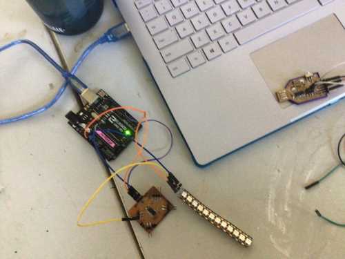
When I ran the code, I got this error: avrdude: jtagmkII_program_enable(): bad response to enter progmode command: RSP_NO_TARGET_POWER. I was very confused by this, and I decided to test the jtag2updi Arduino programmer with a basic Blink code on one of my ATTiny412 blink boards from a few weeks ago. It also did not work with the same error.
I connected my SAMD11C programmer to my Child 2 PCB and kept getting the “pymcuprog.pymcuprog_errors.PymcuprogError: UPDI initialisation failed” error message. I have been seeing this error more often lately, and I was confused why it was occurring. I know that this error is faulty connection to or transmission with the UPDI. Everything was connected correctly. I wondered now if there was a bigger issue with my serial ports.
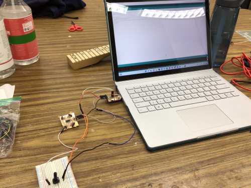
Very frustrated, I decided to do a search for other interfacing examples. I found NY TISCH’sITP Physical Computing, and I was intrigued with the idea of the Processing App responding to the values in the Arduino serial monitor as they were being manipulated by the turning of a potentiometer. This made so much more sense to me. I wondered if there were already compiled Arduino/Processing codes similar to this potentiometer lab. I found the Arduino.cc Create a Graph with Processing.
Once again, I decided to test the codes first using a standard Arduino Uno. I used a small breadboard (mainly to hold the potentiometer as it is being turned) and a potentiometer. The Arduino code (shown below) uploaded with no problems. (It is incredibly short).
void setup() {
  // initialize the serial communication:
  Serial.begin(9600);
}

void loop() {
  // send the value of analog input 0:
  Serial.println(analogRead(6));
  // wait a bit for the analog-to-digital converter to stabilize after the last
  // reading:
  delay(2);
}
I then opened a sketch in the Processing IDE, and I copied and pasted the following code in the work pane.
/* Processing code for this example

  // Graphing sketch

  // This program takes ASCII-encoded strings from the serial port at 9600 baud
  // and graphs them. It expects values in the range 0 to 1023, followed by a
  // newline, or newline and carriage return

  // created 20 Apr 2005
  // updated 24 Nov 2015
  // by Tom Igoe
  // This example code is in the public domain.

  import processing.serial.*;

  Serial myPort;        // The serial port
  int xPos = 1;         // horizontal position of the graph
  float inByte = 0;

  void setup () {
    // set the window size:
    size(400, 300);

    // List all the available serial ports
    // if using Processing 2.1 or later, use Serial.printArray()
    println(Serial.list());

    // I know that the first port in the serial list on my Mac is always my
    // Arduino, so I open Serial.list()[0].
    // Open whatever port is the one you're using.
    myPort = new Serial(this, Serial.list()[0], 9600);

    // don't generate a serialEvent() unless you get a newline character:
    myPort.bufferUntil('\n');

    // set initial background:
    background(0);
  }

  void draw () {
    // draw the line:
    stroke(127, 34, 255);
    line(xPos, height, xPos, height - inByte);

    // at the edge of the screen, go back to the beginning:
    if (xPos >= width) {
      xPos = 0;
      background(0);
    } else {
      // increment the horizontal position:
      xPos++;
    }
  }

  void serialEvent (Serial myPort) {
    // get the ASCII string:
    String inString = myPort.readStringUntil('\n');

    if (inString != null) {
      // trim off any whitespace:
      inString = trim(inString);
      // convert to an int and map to the screen height:
      inByte = float(inString);
      println(inByte);
      inByte = map(inByte, 0, 1023, 0, height);
    }
  }
Immediately, I saw the graphing window. When I turned the potentiometer, the graph began to change (as shown in the two videos below).
The next morning, it was time to get the two codes functioning with my ATTiny1614 PCB. I connected Child 2 to the breadboard with the potentiometer and the SAMD11C programmer.
Once again, I was getting the same errors as I tried to upload the code. I decided to have the IT department at Charlotte Latin School take a look at my laptop to see if there was an issue with my serial ports. After an hour and a half of work on it, it was returned to me (seeimingly better).
I tried to upload the Arduino code onto the “Child 2” PCB (with ATTiny1614 chip), and I got the “Done Uploading” notification! I was so excited, and I quickly started to work on loading the code in the Processing IDE. When I returned to the Arduino IDE, I noticed that the ports were not available anymore for my SAMD11C. I decided to connect the potentiometer (positioned in a breadboard) to my Child 2 PCB and utilize the Tx and Rx pins of a basic Sparkfun Arduino Uno.
Before I connected all of them together, I made sure that there was a basic “Blink” code uploaded onto the Arduino Uno. In that code, I specified that the builtin LED should blink on and off every second. You can see this happening in the following video. This video shows the Arduino IDE and the Processing IDE interfacing using my ATTiny 1614 PCB.
This week’s group assignment was to compare as many tool options as possible. To see our group work, please visit our page. To see my work on this group assignment, please visit this page.