7.0 Computer-Controlled Machining
For this week’s assignment, we were asked to design, mill and assemble something big (~1 m in size). For “extra cresdit”, we could exclude fasteners and glue, and include curved surfaces. Although I was still dealing with issues from the Electronics Design (previous) Week, I was excited to move to this new assignment because I was able to express some creativity. In my final project, I have decided to utilize computer-controlled machining for making the molds of various SpaceX rockets. Since we had to make something big, I could not “kill two birds with one stone” in this week. I wanted to design something with a purpose. So I consulted one of the books that was in the Charlotte Latin School Fab Lab and shared with us by Tom Dubick, called “Design for CNC: Furniture Projects and Fabrication Technique”.
After thumbing through this book, I remembered that a few monthsa ago, I wanted to build a sand play table for my middle grandson. He recently was given kinesthetic sand, and it is stored in a medium-sized plastic bin. Every time that he and his older brother want to play with the sand, they have to put a towel down on the floor, and the cleanup is difficult for them. So I decided to build “my boys” a kinesthetic sand table. I did an Internet search to see if there was a sand table I could use for inspiration. (I realized much later that the sand is not “kinesthetic sand”, it is actually called kinetic sand– good to know). I found This Mobile Sensory Tabel With Four Trays and Lids and thought it would be perfect for my grandsons’ playroom. I wanted to add wheels to it in the end (combining it to look like this one).
Having learned how to make parametric designs in a previous assignment, I actually wound up deciding not to make my design parametric. I knew that I wanted to use plywood that was 0.5” thick, and I felt like this measurement would be somewhat easy to scale. To make the design parametric, I would have to use Fusion 360 or Cuttle. I am fluent in Corel Draw, and given that I was still struggling with the Electronics Design assignment, I needed to use software I would not struggle with– I didn’t have the mental bandwidth to go out of my comfort zone on this one.
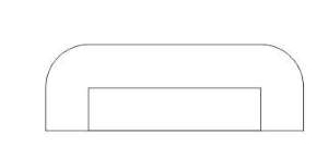
So I began my design in Corel Draw. Before getting too far into my design, I remembered watching an episode of “This Old House” with my husband where they focused on biscuit joints. So I did an Internet search and found this video–How to Make a Biscuit Joint. While I didn’t plan to use actual wooden “biscuits” that are purchased at home improvement stores, I wanted to make the connector joints curved– like larger versions of wooden biscuits. (I would call them “half-biscuit tabs”). When joining two pieces together (at right angles), one piece of the wood would have a curved tab that would fit into a long rectanglular slit on the other piece of wood. I felt that using these “half-biscuit tabs” would allow the two pieces to fit together more snuggly when pounding them into place with a rubber mallet.
Designing for Computer-Controlled Machining
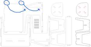
I decided to do a search of Shopbot projects to see if there were any that could be pieced together without using adheasives. This Shopbot CNC Projects was really inspiring, and I wound up deeply examining this desk–“Makers Unite Pay-It-Forward Desk“–which is shown in the image below. (Click on this pdf file to see design information about this desk). The one thing that I really liked about this desk was how the two side pieces fit into the top of the desk with chamfered notches, and once joined, a square wooden peg would hold them both into place.
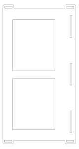
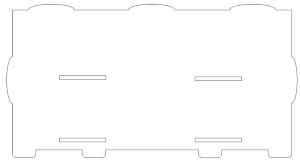
Before I could begin designing a combination version of the desks I found online (mentioned), I needed to know the dimensions of the bins that would hold the kinetic sand in the top. I went on Amazon and began searching for plastic bins that seemed to have somewhat slanted sides and a clearly defined lip at the top. I wound up settling on these Plastic Storage Bins with upper lip dimensions of 14” x 11.75”. The following steps show how I designed the kinesthetic table and the methods I used in Corel Draw. I had planned to use plywood that was 0.5” in thickness, and this was important in designing the slots/connection joints. In Corel Draw, I made the page size 96” x 48”– the size of the Shopbot bed. I wound up needing to make two pages like this to fit all of my pieces for the kinesthetic table.
Desigining the Table Top

- Make a large square with dimensions of 36” x 36”.
- Create a smaller square for the plastic storage bins with dimensions of 13.75” x 11.5”. (These dimensions should accommodate the 14” x 11.75” plastic bins found on Amazon that were previously mentioned).
- Center the newly created rectangle into desired position.
- Copy and paste it three times and arrange/center these around the placement of the first rectangle. (To equally space these drop-in spots for the plastic storage bins, I used rectangles with known desired dimensions as “spacers” and lined the rectangles onto the table’s top, larger rectangle).
- To generate the side “slots” similar to the corners on the “Pay-It-Forward Desk” design, follow these instructions.
| Image | Description |
|---|---|
 |
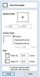
Make an outer rectangle with dimensions of 3” x 1”. Add an inner rectangle with dimensions of 2” x 0.5”, and center it into the larger rectangle. Once centered, click on the center rectangle and use the down arrow on the computer keyboard to make the bottom dimesions of the two rectangles flush. |
 |
Click on the larger, outside rectangle, and unlock the red-circled “lock” in the middle of the four corner-rounding tools. In the top two corner-rounding tools, change the 0.0” to 0.25”. Leave the two bottom corner-rounding tools as they are. |
- Group the two (previously) rectanglular objects by selecting them both and going to Object–>Group–>Group Objects.
- Copy and paste these newly grouped obects twice, and place them on the upper top corners of the larger rectangle.
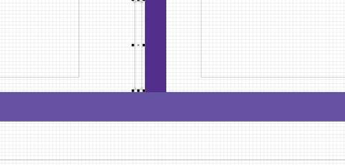
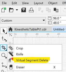
- Use the “Virtual Segment Delete” tool to remove the lines where the objects overlap to generate a solid “handle-like” area on the table’s top.
- Create the slots for the back to fit in by making two rectangles that are 6” x 0.5” in size. Place them at roughly 33% and 66% of the distance from the left side, and 1” away from the long side.
- Create another (vertical) rectangular slot that is 0.5” x 6”, and center it in the center of the table’s top. This will be the spot where the shelf support comes into contact with the top. There will be another shelf support created under it.
- Repeat step 7, but this time, rotate both of them by clicking on them (one at a time) and typing 90-degrees in the “”Angle of Rotate” field in the toolbar.
- Repeat step 8, but this time, adhere these “handle-like” features to the bottome of the table top. SIDE NOTE: It was at this point that I told my son and daughter-in-law the dimensions of the kinesthetic table I was designing for their sons. The “that’s pretty big, Mom” response prompted me to scale the top of the table down quite a bit (to only include two plastic storage bins). I was glad that I ran the dimensions by them at this point; it would have been a lot more work to make modifications to more pieces later. (See modified table top design below.
Designing the Table Sides
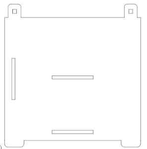
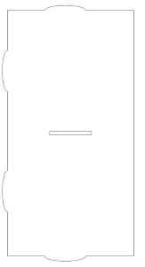
- Create a rectangle with dimensions of 20” x 18”.
- To create the “slots” for the upper corners to fit into the slots of the table top’s corners, repeat step 5 above, but make the outer rectangle 2” x 2”, and the inner rectangle 0.5” x 0.5”. Round the corners of the larger, outside rectangle using 0.5 as the rounding value for the top two corners only.
- Group the newly formed “notch”.
- Copy and paste it, and place the two notches onto the top of the large rectangle.
- Once again, use the Virtual Segment Delete button to remove the overlapping lines to make it all one piece.
- To create the bottom legs of the table, make an outer rectangle with 3” x 1” dimensions.
- Round the top two corners of this rectangle using rounding tool dimensions of 0.5”.
- Copy and paste this newly created leg twice, and place both copies onto the bottom of the rectangle.
- Repeat step 5 to join it and make it all one piece.
- To make the slots where the two horizontal shelves will connect, make a horizontal rectangle that has dimensions of 6” x 0.5”.
- Copy and paste this rectangle twice, and using rectangles with known dimensions, place the slots into place on the side of the table, making sure they are perfectly aligned and parallel to each other.
- Finish the side of the table by creating a vertical slot (dimensions of 0.5” x 6”), and place it to the desired vertical position. I wanted the back piece of the table to come in slightly, so I placed this vertical slot 1” away from the side.
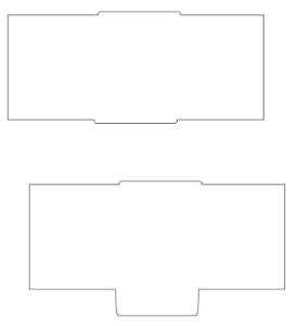
Designing the Back of the Table
- Create a large rectangle that has dimensions of 36” x 18”.
- Copy and paste the bottom leg template from steps 6 & 7 above four times.
- Add the four legs to the bottom of the rectangle, making sure to space them apart to desired positions.
- Use the Virtual Segment Delete button to remove the overlapping lines to make it all one piece.
- To generate the horizontal slots for where the shelves will fit, repeat steps 10 & 11 above. There will be two separate shelves, and the slots will have to be reflected oppositely on each side of the back piece.
- Create the rounded “half-biscuit” tabs by making an oval that has 6” x 1.5”. Align two of these “half-biscuits” so that they are aligned with the two slots previously generated in the top of the table.
- Overlap the ovals halfway on the rectangle in desired position.
- Use the Virtual Segment Delete button to remove the overlapping lines to make it all one piece.
- Repeat steps 5-8, but this time, make one vertical oval that is 1.5” x 6”. This should align with the vertical slot created on the side piece of the table.
Designing the Shelves
Both shelves will be identicial, and they will need to have two slots that fit into the back of the table and one slot that allows a shelf support to be inserted into it.
- Create the large base rectangle that has dimesions of 18.5” x 36”.
- Create the rounded “half-biscuit” tabs by making an oval that has 6” x 1.5”. Align two of these “half-biscuits” so that they are aligned with the two slots previously generated in the back of the table.
- Overlap the ovals halfway on the rectangle in desired position.
- Use the Virtual Segment Delete button to remove the overlapping lines to make it all one piece.
- Repeat steps 2-4 twice, generating “half-biscuits” that are vertical and align with the vertical slots on each side of the table.
- Make a vertical slot (dimensions of 0.5” x 6”), and place it in the center position where the shlef support will fit.
Designing the Shelf Supports
The two shelf supports are not identical. One shelf support will interact with the top of the table and the upper shelf, and the other shelf support will interact with the upper shelf, lower shelf, and the floor.
Upper Shelf Support 1. Create a rectangle that is 18.5” x 7.5”. 2. Create a rectangle that is 6” x 0.5”, and round all four corners 0.2”. 3. Center the rectangle in the midpoint of the longest side, and overlab it halfway over the large rectangle. 4. Use the Virtual Segment Delete button to remove the overlapping lines to make it all one piece. 5. Repeat steps 2-4, but adhere the rectangle to the bottom long side of the shelf support.
Lower shelf Support 1. Repeat steps 1-4 above. 2. For the bottom leg that slips into the long slot in the bottom shelf and comes into contact with the floor, create a rectangle with 6” x 2” dimensions. 3. Round all four corners of the rectangle 0.5”. 4. Center the rectangle in the midpoint of the longest side, and overlab it halfway over the large rectangle. 5. Use the Virtual Segment Delete button to remove the overlapping lines to make it all one piece. 6. Repeat steps 2-4, but adhere the rectangle to the bottom long side of the shelf support.
I saved my Corel Draw files in three formats: .CDR, .DXF, and .SVG.
Milling with Computer-Controlled Machining
NOTE: Images used here were snipped using the snipping tool of my Windows laptop from both this Products- Aspire page and this User’s Manual.
Before testing my design on the Alpha Shopbot, I did three, small-scaled test cuts using the laser cutter in the Charlotte Latin School Fab Lab.
|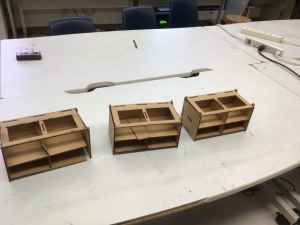 |In the first prototype, I had to make modifications in the dimensions of the back piece. In the second prototype, the shelf supports were too short, and I had to modify their height dimensions. The third and final prototype fit together perfectlly after making the modifications.
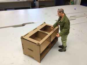
This is my final cardboard prototype with classmate, Charlie Horvath’s GI Joe next to it. (Charlie was using this same GI Joe with his small-scale prototype).
For me this week, the biggest learning curve was in preparing files in Aspire and then utlizing those files for milling on Charlotte Latin School’s Shopbot. Colleague/classmate, Nidhie Dhiman was a huge help in setting up my files for milling in Aspire software (which we use at the Charlotte Latin School Fab Lab for interfacing with the Alpha Shopbot).
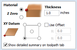
The first thing I did was upload the SVG file that contained the majority of my kinesthetic table parts into Aspire. On the left side of the screen, I “set up” the document by choosing a materials thickness of 0.484” and de-selecting the “Use Offset” box.
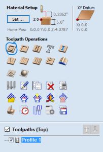
I added dogbones to all of the slots and hard, 90-degree corners in the designs. This was difficult at first because Aspire wanted me to use a 1/8” tool/bit for milling my pieces because the slots were 0.5” in width. I was eventually able to override this and use a 1/4” tool/bit.
Once all of the dogbones were added, I began to create the Toolpaths for the holes and the non-holes in the design.
For the holes, I selected inner pathways, and for the non-holes, I selected outer pathways. I added tabs to the non-hole pieces, and I saved the holes and non-hole pieces as separate profiles. However, when I tried to save the toolpaths, I was getting an error messagae about “unjoined curves” in my design. To resolve this issue, I did an Internet search and found this site–Joining Curves. So I went back to Corel Draw into my design and closed/joined all curves in each piece of the table. I re-exported the files and began the Aspire process again. This time, I was able to save the toolpaths.
I placed the Aspire file into our “Endproj” folders at the Charlotte Latin School Fab Lab, and headed to the Alpha Shopbot to cut out my designed table pieces. I opened the already-compiled workflow for the Alpha Shopbot at the Charlotte Latin School Fab Lab. When I downloaded the Aspire file in the computer wired to the Alpha Shopbot and I clicked on the “estimated time” it stated that the estimated time for the job was over four hours.
After being in the Fab Lab for nearly twelve hours already, I had a legitmate meltdown. There were numerous other people who were lined up to use the Shopbot after my “turn”, and I allowed others to use it in my place. Colleague, Zack Budzichowski had been at the Fab Lab helping everyone use the Shopbot that day, and after a couple of hours, he and Tom Dubick realized that there was an issue with the speed rates when we transferred our files from the computers in the Fab Lab and the computer wired to the Alpha Shopbot. With this realized, we re-calculated my job to really only take twenty minutes. This was quite the difference!
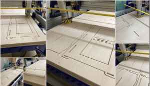
I was finally able to cut my kinesthetic table again, but this time, I had Tom Dubick with me in order to ensure I was setting everything up properly. We wound up cutting the pieces (the majority of them) in the first “page” of my design file. We then moved on to cut the remaining two pieces in the second “page” of my design file.
After we zeroed out the Z axis and set new axes (of X=4, Y=4), we started the job. It was close to midnight, and when the job began, the drill bit dragged across the wood, and I immedaitely hit the stop button. In examining our file, we realized that I had not “unclicked” the “Offset” box in the initial setup of the document.
We re-calibrated all axes again and started the job. This time, the cut went smoothly.
On March 14, my husband (Matt Morrow) kindly sanded the pieces for my kinesthetic table while I was in a meeting. I then began to assemble the table outside of our house. In doing this, I realized that none of the pieces had the 0.5”-wide slots in them. I literally had to re-cut the entire design again. The video below shows this; I was so disappointed in my careless mistake. I never even noticed that the slots were missing while cutting them bringing them home. I had been at the Fab Lab for fifteen hours that day, and this was the only “excuse” I was allowing for myself.
||
On Tuesday, March 15, I headed back over to the Charlotte Latin School Fab Lab to cut the large pieces again. Thankfully, there was still a full sheet and a partial sheet of 0.5” plywood left and no one else was using plywood with that thickness.
When loading the files into Aspire this time, I once again imported the .SVG files, and I noticed that the slots were all missing– just as before. This is what had happened the first time– Aspire did not recognize all of the components in the .SVG’s. So, I brought in the .DXF files.
This time, all of the components in my kinesthetic table were there, but Aspire would not allow me to make a dogbone in the 0.5” slots/holes. Tom Dubick showed me a work-around where I could re-draw the rectangles, add dogbones to them, and use them in place of the previous slots/holes.
I had to make sure to delete all of the old rectangles though. As I went to set up my toolpaths, I once again got the error message about “unclosed curves”. Classmate, Charlie Horvath showed me how I could select the object’s outline and use the “Close Curve” tool.
Once I had the files set up for milling using the Alpha Shopbot, I headed into the other room to get started. I milled the large (part 1) page of pieces first, and had no issues.
I only had one more piece to mill to complete the second cut, and this job was estimated to take a little over five minutes. That’s when troubles began, and it wound up taking more like 45 minutes. I was trying to save material by using a piece of plywood that had already had cuts out of it. I zeroed the Z axis off of the bed using the plate, and then set the “home” for my job at X= 2, Y= 2. I did an air cut to make sure my design would indeed fit in the area of the plywood that I had chosen. I then went to perform the real cut.
When I started the job, I was running the toolpath for the hole first. For an unknown reason, the drill bit went straight into the board at the very start of the job rather than jogging out to the specified hole.
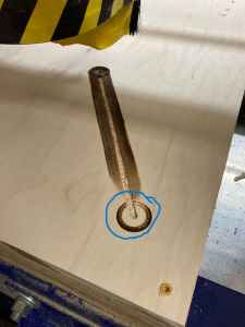
Classmate, Charlie Horvath and I worked to determine what had happened, but we were never able to understand how this error occurred. We both worked again to re-home the drivers, and attempt the job again. This time, the bit went into the wood at the same spot and started to drag across the surface. The wood had been badly burnt, and now we needed to replace the bit.

Very confused, we changed the bit, and I hurt my left thumb while trying to loosen the collet (which was extremely tightened). Although we were using all safety precautions, my thumb was throbbing, and I wondered if it was fractured. After replacing the broken bit, we re-calibrated the Z axis from the bed again, and re-established the X= 2, Y =2 “home”. We ran the final job that cut out my final piece with no more issues.
Assembling Furniture (~1m) from Computer-Controlled Cutting
After going back to the Charlotte Latin School Fab Lab on Tuesday, March 15, to re-cut my kinesthetic table pieces, I had to sand them again.
||
After sanding for a very long time (I am sure my neighbors hate me now), I knew that the sanding was going to take much longer than I had planned. The pieces that my husband sanded for me the day before were fitting together perfectly, but the re-cut pieces were needing to be pounded in. I knew I wanted to sand the pieces more, so I stopped recording. It was during this session that I realized that I had accidentally returned the two shelf supports to the Fab Lab with the other incorrectly cut pieces. This time, I planned to sand more, and then return to the Fab Lab to retrieve the missing pieces– hoping that Dr. Gershenfeld would not call on me during the Wednesday meeting.
After picking up the two missing shelf supports (on Thursday, March 17) for my kinesthetic sand table, and a lot more sanding, I was able to get all of the pieces to fit together nicely.
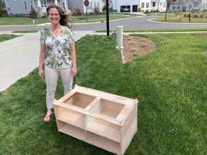
In the end, I was most proud of the two shelf supports. I had designed them both to sit 0.25” into their respective 1/2” slots. As I put the table together, it seemed as though the design was over-constrained, but the fits/joints were actually just right. If I decided to make this table again, I would add 1/16” to each slot in both the X and Y directions to allow for less sanding. I would also add labels for each side/joint to know where they belonged.
Side Issue This Week
To make the write-up for this week especially fun, Visual Studio Code decided to update in the middle of my work in the app. Suspending my work for a few minutes, I allowed the update to conitnue. However, when I tried to continue using it, I could not open Visual Studio Code at all. The images below show the exciting “off-roading” I got to do for about an hour.
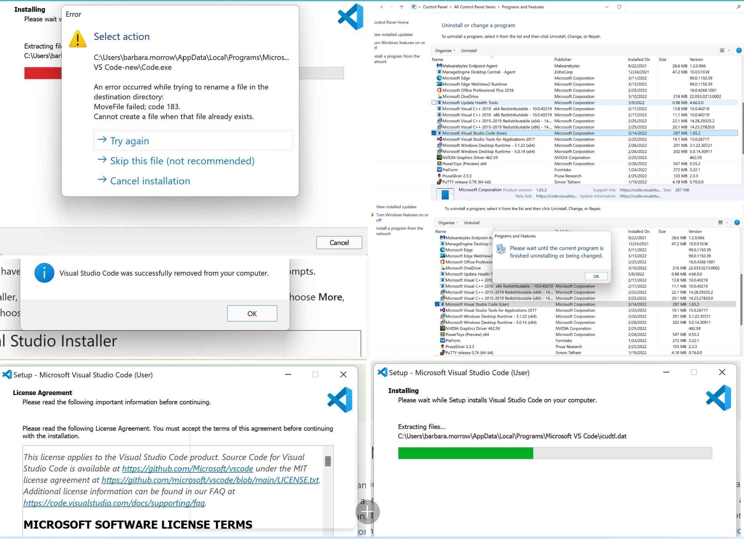
I went to Visual Studio 2022 and re-downloaded it.
To see the group work with Computer-Controlled Machining done this week, please visit our page. To see the work I did on this group project, please see this page.