13.0 Inputs
I have been looking forward to this week for a long time– I think because I was planning to use a PIR Sensor. A PIR (or Passive Infra-red ) sensor detects motion and is often used in security systems.
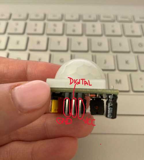
When I outlined my ideas for my final project, I was unsure of what I would do for “Inputs Week”, but after numerous conversations, I was happy to learn about PIR sensors. Since we already had through-hole PIR sensors in the Charlotte Latin School Fab Lab, I was excited to get started with using one.
The first thing I did was look at this site, which provided information about PIR Sensors. To understand how to conenct a PIR Sensor to an Elegoo Uno R3, I viewed this site. I then read information on PIR Motion Sensor Hookup Guide. About halfway down on the page, it was suggested to read information about Pull-Up Resistors. I remembered that a few weeks back, we were using our buttons on our PCB’s as pull-up resistors.
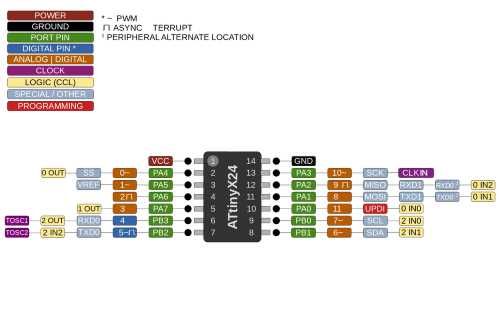
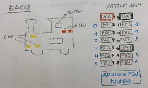
The first thing I needed to do was have a copy of the ATTiny 1614 chip pinout. The following two images were found at this site handy.
 |
 |
|---|---|
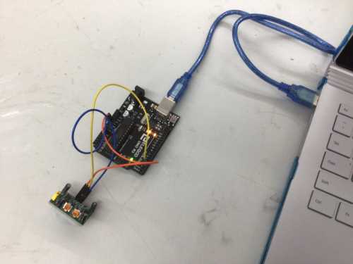
Before using a 1614 breakour board with my SAMD11C programmer, I connected my PIR sensor to an Arduino and got it working. I also wanted to review the code and functioning of my RGB LED from Embedded Programming week. My plan for this week is to combine the two– a PIR sensor and an RGB LED in a breakout board. I want the RGB LED to always be flashing the rainbow fade when the PIR sensor does not detect movement and to change to green only when movement is detected. Ideally, for my final project, I would like to have the PIR sensor project a message onto an LCD screen stating when the next launch is. The following images and video clips show me programming the PIR sensor with the Arduino Uno and the RGB LED with my SAMD11C programmer.
| PIR Sensor with Arduino | RGB LED with SAMD11 |
|---|---|
 |
 |
| This is how the through-hole PIR sensor was connected to the Arduino Uno. Pin 2 was utilized. | This shows the RGB PCB connected to the SAMD11C programmer. |
I (very arrogantly) thought that using my SAMD11 to program the PIR sensor was going to be straightforward and easy. However, I ended up in a rut for two days, undable to get out. Using the following code, I connected the PIR Sensor to pin 4 on the breakout board (which corresponds to pin 2 on the Arduino). But when it came to connecting the VCC and GND connections, I was puzzled.
 |
 |
|---|---|
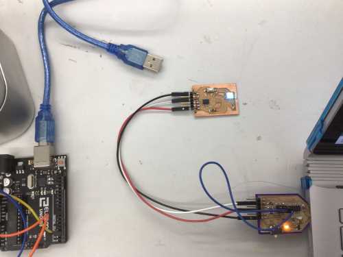
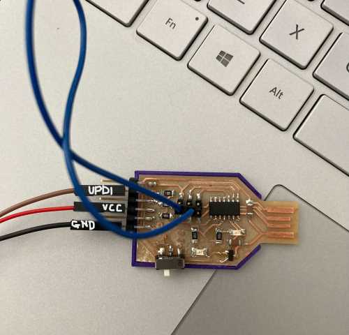
Since there are three connections from the SAMD11C programmer (UPDI, VCC, and GND), it would be easy if I could just connect the three pins on the PIR sensor straight to the pins on the SAMD11C. But this won’t work because the SAMD11C is a programmer and not a target board. Those three pins on the SAMD11C programmer would need to be connected to the ATTiny 1614 breakout board as shown below.
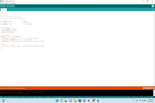
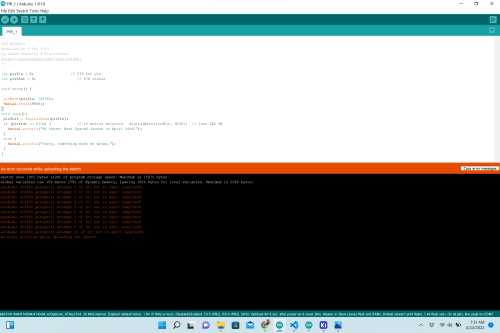
I assumed that I either needed to make a splitter wire to connect them, or use a 5V power supply to connect the VCC/GND pins on the PIR sensor. As I tested many different connections and codes, I got the same error message (shown below) every time.
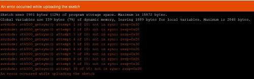 |
“avrdude: stk500_getsync() attempt 1 of 10: not in sync: resp=0x30” |
|---|---|
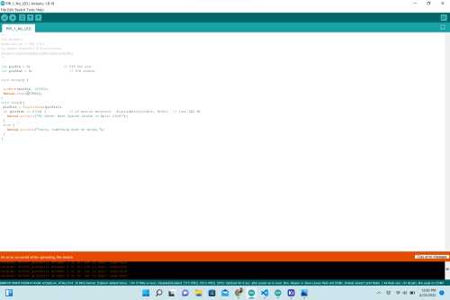
The following table shows the things I tried, and the code used is shown. I found this code on Arduino’s PIR Motion Sensor: How to Use PIRs w/Arduino & Raspberry Pi
/*
PIR HCSR501
modified on 5 Feb 2019
by Saeed Hosseini @ ElectroPeak
https://electropeak.com/learn/guides/
*/
int ledPin = 13;                // LED
int pirPin = 2;                 // PIR Out pin
int pirStat = 0;                   // PIR status

void setup() {
 pinMode(ledPin, OUTPUT);
 pinMode(pirPin, INPUT);
 Serial.begin(9600);
}
void loop(){
 pirStat = digitalRead(pirPin);
 if (pirStat == HIGH) {            // if motion detected
   digitalWrite(ledPin, HIGH);  // turn LED ON
   Serial.println("Hi there! Next SpaceX launch is Apirl 23rd!");
 }
 else {
   digitalWrite(ledPin, LOW); // turn LED OFF if we have no motion
 }
}
| Image | Explanation |
|---|---|
 |
For the VCC and GND connections between the SAMD11C programmer the PIR sensor and the ATTiny1614 breakout board. Obviously, this did’t work, and I wondered if– by splitting the out |
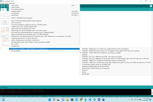 |
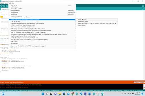
I thought perhaps I had chosen the wrong board. This shows I had the correct board. |
 |
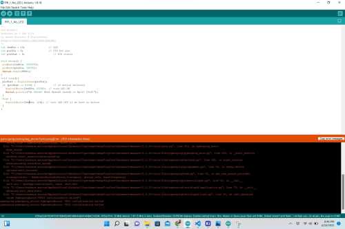
This is the code I had been using. It utilizes both the serial port and the builtin LED on an Arduino Uno. |
 |
I went onto the Internet and searched to see if anyone had used a PIR sensor with an ATTiny1614. I found Adrian Torres’s site, and I wondered if his code would work. It did work with the Arduino. |
 |
I thought perhaps the file wasn’t uploading because I had the wrong baud rate. The code specifies 115200, so I changed it to 9600.) |
| This video shows me testing the code without the LED statements in it. | |
 |
I thought that maybe because this code utilized the built-in LED on the Arduino Uno, and my ATTiny1614 breakout board did not, that the code was not working. |
I sat down to think through a new breakout board. On Friday, April 22, I designed the following schematic in KiCAD, and I started to design the PCB.
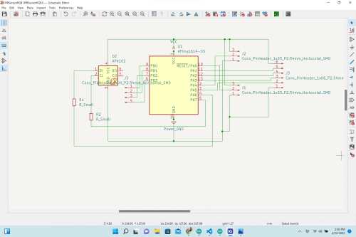 |
In the schematic, I decided to look back at my RGB LED PCB (with ATTiny 412 chip) breakout board and try to incorporate it into this new board. With the pins I had remaining, I connected them to male header pins with the hope that I could possibly use the four grouped together to control one of the stepper motors needed for my final project. I also connected the remaining three in the same manner to possibly use them later as well. I was unsure if this schematic was correct, and I had two classmates– Aaron Logan and Nidhie Dhiman– look over it. They both thought it would seemingly work. |
|---|---|
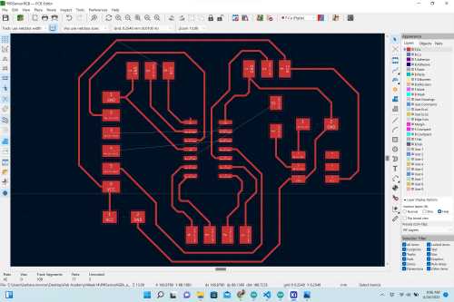 |
I had been able to remove most of the rat’s nests, but there were a few remaining lines that I could not connect without the use of a 0-Ohm resistor to serve as a “jumper”. |
After putting this time and energy into designing the schematic and PCB (even though it was not completed), it dawned on me that I could actually test the PIR sensor in this wiring scenario by adding two jumper wires to the ATTiny1614 breakout board.
| Image of Error | Explanation of What Was Done |
|---|---|
| This video shows me cutting the traces from pins 8 and 10 on the ATTiny16614 breakout board and connecting short white jumper wires connecting pin 8 to the VCC pin (Pin 1) and pin 10 to the GND pin (Pin 14). | |
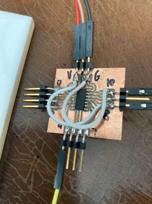 |
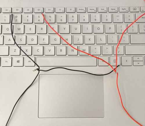
I added jumper wires to the ATTiny1614 breakout board connecting the VCC and GND (on the ATTiny1614’s pin 1 and pin 14 resepectively), and connected the digital pin of the PIR sensor to pin 4 of the ATTiny1614 breakout board. |
 |
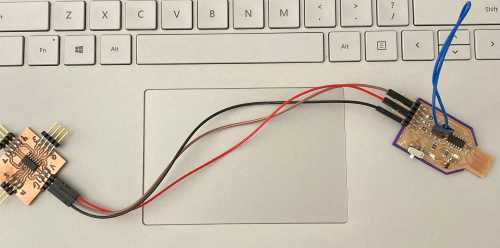
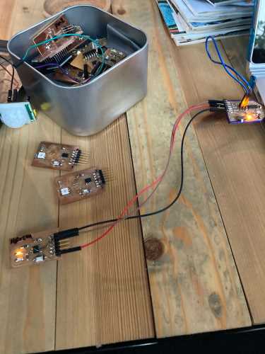
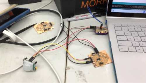
I connected a 5V external power supply to the VCC and GND pins of the PIR sensor, and connected the Digital Pin to pin 4 of the ATTiny1614 breakout board. (The VCC, UPDI, and GND pins of the ATTiny1614 were connected to the VCC, UPDI and GND pins of the SAMD11C programmer). |
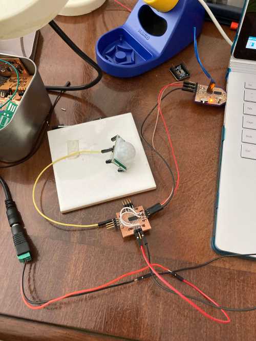 |
I utilized the the breakout board with the jumper wires and also connected the 5V external supply. |
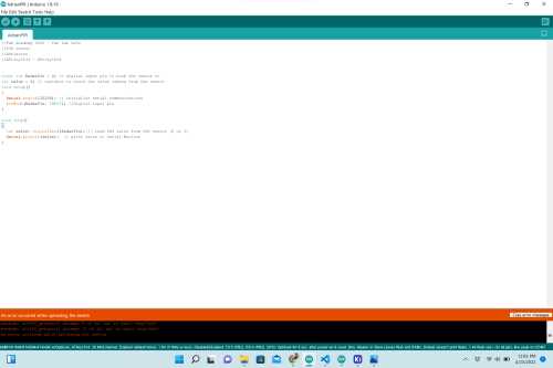 |
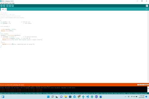
I tried the code from Adrian Torres’s site with the new VCC/GND. |
//Fab Academy 2020 - Fab Lab León
//PIR sensor
//Adrianino
//ATtiny1614 - ATtiny1624


const int RadarPin = 2; // digital input pin to hook the sensor to
int value = 6; // variable to store the value coming from the sensor
void setup()
{
  Serial.begin(115200); // initialize serial communications
  pinMode(RadarPin, INPUT); //digital input pin
}

void loop()
{
  int value= digitalRead(RadarPin); // read the value from the sensor (0 or 1)
  Serial.println(value);  // print value to Serial Monitor
}
Between all of my testing and getting errors, I did Internet research in what could be happening. I found this site that showed me how I can change the “If, Else” portion of the code, and it helped me to understand how the “If, Else” statement can be used for my project (with the RGB LED color values).
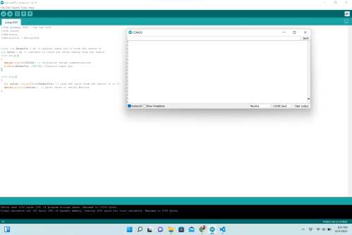
The followig two videos show me changing the pins in the original code.
| Changing Pins– Attempt 1 | Changing Pins– Attempt 2 |
When nothing else was working, I reached out to Dr. Adam Harris for help and explained all that I had done to test the PIR sensor using the breakout board. He felt that there is connection issue and not a code issue, and he suggested that I try to use the ATTiny1614 breakout board to do something else (since it worked before with my stepper motor).
 |
|---|
| I connected the stepper motor to the ATTiny1614 breakout board exactly as I did during Output Week. I selected the ATTiny 1614 as my board and chip as shown in this image. When I uploaded the code, I got the exact same error message that I have been gettign all weekend. |
/*
 Stepper Motor Control - one revolution

 This program drives a unipolar or bipolar stepper motor.
 The motor is attached to digital pins 8 - 11 of the Arduino.

 The motor should revolve one revolution in one direction, then
 one revolution in the other direction.


 Created 11 Mar. 2007
 Modified 30 Nov. 2009
 by Tom Igoe

 */

#include <Stepper.h>

const int stepsPerRevolution = 200;  // change this to fit the number of steps per revolution
// for your motor

// initialize the stepper library on pins 0 through 3:
Stepper myStepper(stepsPerRevolution, 0, 1, 2, 3);

void setup() {
  // set the speed at 60 rpm:
  myStepper.setSpeed(60);
  // initialize the serial port:
  Serial.begin(9600);
}

void loop() {
  // step one revolution  in one direction:
  Serial.println("clockwise");
  myStepper.step(stepsPerRevolution);
  delay(500);

  // step one revolution in the other direction:
  Serial.println("counterclockwise");
  myStepper.step(-stepsPerRevolution);
  delay(500);
}
I wondered if my SAMD11C programmer was faulty. So I pulled out my Copycat Blink ATTiny 412 breakout board from Embedded Programming Week and connected it.
 |
|---|
| I connected the SAMD11Cprogrammer and modified the code (changed the HIGH time to 5000 ms– something that would be noticeable). The code uploaded properly, and the LED’s behaved as they should with the new code. |
/*
  Blink

  Turns an LED on for one second, then off for one second, repeatedly.

  Most Arduinos have an on-board LED you can control. On the UNO, MEGA and ZERO
  it is attached to digital pin 13, on MKR1000 on pin 6. LED_BUILTIN is set to
  the correct LED pin independent of which board is used.
  If you want to know what pin the on-board LED is connected to on your Arduino
  model, check the Technical Specs of your board at:
  https://www.arduino.cc/en/Main/Products

  modified 8 May 2014
  by Scott Fitzgerald
  modified 2 Sep 2016
  by Arturo Guadalupi
  modified 8 Sep 2016
  by Colby Newman

  This example code is in the public domain.

  https://www.arduino.cc/en/Tutorial/BuiltInExamples/Blink
*/

// the setup function runs once when you press reset or power the board
void setup() {
  // initialize digital pin LED_BUILTIN as an output.
  pinMode(1, OUTPUT);
  pinMode(3, OUTPUT);
}

// the loop function runs over and over again forever
void loop() {
  digitalWrite(1, HIGH);   // turn the LED on (HIGH is the voltage level)
  delay(5000);
  digitalWrite(3, HIGH);   // turn the LED on (HIGH is the voltage level)
  delay(5000);    // wait for a second
  digitalWrite(1, LOW);    // turn the LED off by making the voltage LOW
  delay(1000);                       // wait for a second
  digitalWrite(3, LOW);    // turn the LED off by making the voltage LOW
  delay(1000);
}
I decided to pull out the ATTiny 1614 chip that I had soldered onto an SOIC and try using a breadboard to get the PIR sensor working. As I did this, I decided to look again at the options when I select boards.
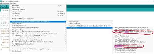
| Image | Description |
|---|---|
 |
Error Message: “pymcuprog.pymcuprog_errors.PymcuprogError: UPDI initialisation failed”. |
After testing both of the ATTiny1614 breakout boards (one with the jumper wires connected to the VCC/GND and one with an external power source), I could only get the code to load on the board that was being powered externally. Even though the code was loading onto the one board, I was not able to see the output message (“Hi there. The next SpaceX launch is on April XX!” in the serial monitor when THE PIR sensor detected motion. Knowing that Dr. Adam Harris was coming to work with Charlotte Latin School students, I planned to wait until he was finished with the high school students and get help with the serial monitor. I also wanted to discuss the schematic I designed with Dr. Harris. I wanted to learn the appropriate way to power the PIR sensor (through the breakout board I had designed, or with an external 5V power supply).
On Monday, April 25, fellow Fab Academy student, Aaron Logan and I were waiting for Dr. Harris to arrive, and we were discussing the sensors we were each using. Both of us were having the same trouble determining how to use the serial monitor with the new breakout boards. We knew that the breakout boards were accumulating data, but there was no way for it to leave that board. As we discussed this, we simultaneously realized that we needed to do something with the UPDI pin coming out of the SAMD11C. Also, after reviewing Dr. Harris’s “SAMD11C Multi-use Board” page. I remembered reading that the jumper wire placed on the top of the board (seemingly connected to itself) is what made it able to be a UPDI programmer. Aaron and I had the thought that we needed to remove that jumper wire (disable 2-way communication) in order to allow the incoming data from the PIR sensor to be displayed on the serial monitor.
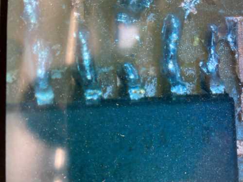
Exmining my PCB’s, I knew they were very rough looking since they were milled. (I believe the bit was damaged, and this was the reason for the “sloppy” traces). I examined the board with the jumper wires under the microscope, and I thought one of the pins could use more solder. (See image below).
In our discussion with Dr. Harris that evening, we felt validated in learning that we were on the right track. Dr. Harris explained to us that we needed to simply remove the “SERIAL_8E2” from the following code.
void setup() {

   SerialUSB.begin(0);
   Serial1.begin(57600, SERIAL_8E2); //Adjust baud rate and use SERIAL_8N1 for regular serial port usage
}

void loop() {
   if (SerialUSB.available()) {
      Serial1.write((char) SerialUSB.read()); //Send stuff from Serial port to USB
   }
   if (Serial1.available()) {
      SerialUSB.write((char) Serial1.read()); //Send stuff from USB to serial port
   }
} //end loop
The new code for the SAMD11C is shown below without the “SERIAL_8E2”. In looking at it now, I wish I had maid attention to the notes Dr. Harris added– especially in the second line.
void setup() {

   SerialUSB.begin(0);
   Serial1.begin(9600); //Adjust baud rate and use SERIAL_8N1 for regular serial port usage
}

void loop() {
   if (SerialUSB.available()) {
      Serial1.write((char) SerialUSB.read()); //Send stuff from Serial port to USB
   }
   if (Serial1.available()) {
      SerialUSB.write((char) Serial1.read()); //Send stuff from USB to serial port
   }
} //end loop
With the schematic of my breakout PIR_RGB LED PCB, and a good start to remvoing the “rats nests” in the KiCAD PCB editor, I was trying to not have to resort to using 0-Ohm resistors as jumpers. After working on this for over two hours, I decided to start from scratch in connecting my traces. I spent roughly another two hours trying to clear the “rats nests” again, and still, I could not make it happen. I started over again for a third time, and this time, I resorted to using 3, 0-Ohm resistors. I had many pins leading to VCC and GND. As I complained about this, Aaron Logan mentioned to me how he and his group (during machine week) were able to create a separate “ground” board. Although I wanted to try it, I was so far into the design that I did not want to throw out the work I had already done. (I would later regret this as I saw Aaron’s design of his own PCB board designed this way working well for him).
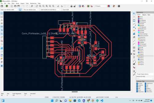
The following image shows the final PCB that I designed for this week.
As I went to stuff my PCB, I realized my Dotstar 50/50 LED’s were missing. Since this is “INPUT” week, I decided to not include the RGB LED’s on the breakout boards and add them later. Tom Dubick was able to get more RGB LED’s but due to “supply chain issues”, they were very expensive.
The following video shows me milling my PIR PBC breakout boards.
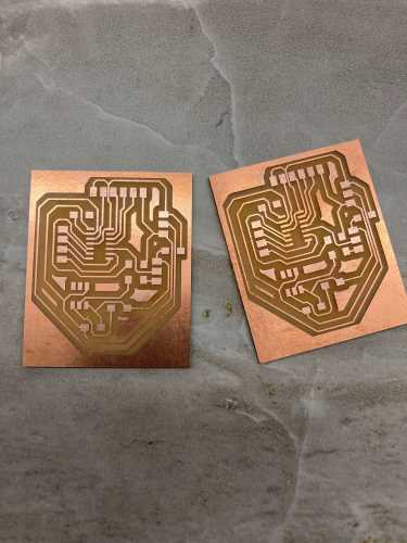 |
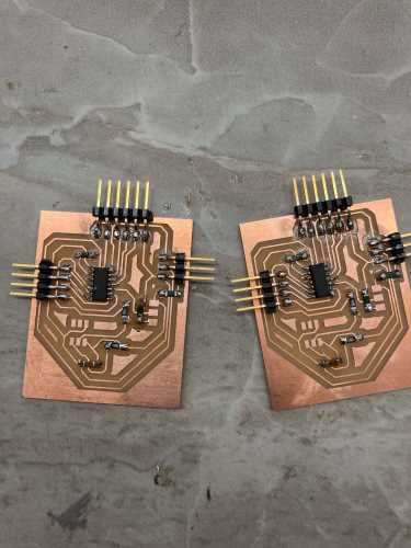 |
|---|---|
| I milled two boards (as I always have done). I used brand new bits, and they came out very clean, unlike the last boards I milled. | I stuffed both boards, but I have to wait for the new RGD LED’s to arrive to add them to the board. I accidentally forgot to solder a 3-pin header to both boards, but I wound up adding them later (when I realized it). |
The following video shows me stuffing my PIR breakout boards.
Now that the breakout PIR PCB’s were fully stuffed, I followed the following steps to demonstrate that the PIR sensor was indeed functioning properly.
| Step # | Description |
|---|---|
| 1 | Using the ATTiny 1614 pinout, connect the PIR sensor to the board. (With the board oriented with the 6-male header pins on the left, connect the wires to the set of 3-pin headers in the upper right.) |
| 2 | In the 3-pin headers in the upper right, connect the GND on the left, the UPDI pin in the middle, and the VCC on the right. |
| 3 | Connect the jumper wire from the PIR sensor to the pin second from the bottom of the 6-pin male headers. Connect the power |
| 4 | With the SAMD11C programmer, send PIR_1 Arduino code to the breakout PIR PCB. |
| 5 | Pull assembly out of USB port. Remove the jumper wire from the top of the SAMD11C. |
| 6 | Connect the Rx pin on the breakout PIR PCB to the Tx pin on the SAMD11, and the Tx pin on the breakout PIR PCB to the Rx pin on the SAMD11. |
| 7 | Upload Dr. Harris’s code to the breakout PIR PCB. Code iS BELOW. |
| 8 | Open the serial monitor and determine if movement is detected. |
int ledPin = 6;                // LED
int pirPin = 1;                 // PIR Out pin
int pirStat = 0;                   // PIR status

void setup() {
 pinMode(6, OUTPUT);
 pinMode(pirPin, INPUT);
 Serial.begin(9600);
}
void loop(){
 pirStat = digitalRead(pirPin);
 if (pirStat == HIGH) {            // if motion detected
   digitalWrite(ledPin, HIGH);  // turn LED ON
   Serial.println("Hi there! Next SpaceX launch is <FILL IN DATE HERE>!");
 }
 else {
   digitalWrite(ledPin, LOW); // turn LED OFF if we have no motion
 }
}
The following video shows me following these steps. However, I used an Arduino that had been converted into a jtag2UPDI programmer to upload the code onto the ATTiny 1614 PCB. The first time I did this (in the video below), I used my SAMD11C programmer to upload the code, but it doesn’t show the full wiring (aka “the proof”) of the SAMD11C with the ATTiny 1614 PCB.
The video below shows me repeating this process (for full video evidence) using my jtag2UPDI programmer. My SAMD11C programmer was malfunctioning, and I was unable to get it back up and running again. In the code that was uploaded to the ATTiny 1614 PCB, if motion is detected (causing the pirStat to be “HIGH”), then the next SpaceX launch will be printed in the serial monitor– “Hi there! Next SpaceX launch (at that time) is May 26th”. If there is no motion detected by the PIR sensor (causing the pirStat to NOT BE HIGH), then there will be nothing written–no statement at all–in the serial monitor.
This week, for our group project, we were asked to probe an input device’s analog levels and digital signals. To see our group work, please visit our site at this link. To see my work on this group assignment, please visit this page.