7.5 Group Project- Computer-Controlled Machining
This week, our group was asked to outline and design the Charlotte Latin School Fab Lab safety for using computer-controlled machining (aka the Shopbots at CLS). We were asked to test runout, alignment, fixturing, speeds, feeds, materials and toolpaths for our Shopbots.
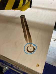
While we worked together before starting our individual projects, I personally wound up learning a lot about these things when using the Shopbot for my individual project. As a group (at that point), we gathered on Wednesday evening (March 9). Charlie Horvath (who has experience working with CNC machines) showed us how to use the runout indicator tool.
On Sunday, March 13, we did more tests with both the large Shopbot and the smaller shopbot. While I was primarily in the CLS Fab Lab to cut my “Kinesthetic Table”, we did a lot of collaboration work together as a group.
One thing that relates to my work for the group was the speeds and feeds. As mentioned on my “7a” page, the speed and feed rate was incredibly large due to software issues between computers.
I contributed to this work by adding the following information.
Speeds/Feeds
Speeds (speed rate) and feeds (feed rate) are important in computer-controlled machining—especially in preserving the quality of the finish on the material being cut. The speed rate is the speed of the spinning spindle (measured in revolutions per minute—or RPM). The feed rate is the speed that a bit moves/cuts through the actual material (measured in inches per minute—or IPM). Having excessively large chips can damage the bit, and this can be prevented by lowering the feed rate. On the Alpha Shopbot at the Charlotte Latin School Fab Lab, feed rates and speed can be controlled and monitored by determining the chip load for the material and using an RPM that aligns with that chip load (found in the chart on pages 9-12 of this site. The cutting speed should be increased gradually until the piece being cut starts to move, and the speed should be decreased 10% at that point. When the finish on the material starts to break down, the RPM can be increased once again until acceptable. In doing this, the largest (“waste”) chips will be minimized. The following websites are examples of speeds and feed calculators that can be used to make adjustments.
Feed rates and speed rates both vary with the material being cut. It is important to allow the bit to move through the material as quickly as possible (without tearing up the material’s finish—as mentioned above). If the tool rotates on one place for too long, the rotating bit will drastically increase friction, and large amounts of heat from this friction can cause the material to burn.
| |
| |
|
As a rule, a fast speed with slow feed can yield burning and/or melting, and slow speed with fast feed can cause bit dulling. It is important to keep feeds and speeds in balance. Allowing two passes—pass 1, the roughing pass, and pass 2, the finishing pass- produce different chips. Pass 1 produces a larger amount of chips than pass 2.
Materials
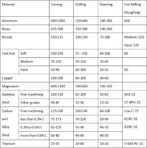
CNC machines can mill: medium density fiberboard (or MDF), plastics (Delrin/Acetal Copolymer), machine-able wax, polyurethane boards, foam, and even metals (aluminum, brass, bronze, etc). When performing the first pass (roughing cut) should have a feed rate of about 0.005-0.020 IPR (inches per revolution), and the second pass (finishing cut) should have a feed rate of about 0.002-0.004 IPR. Each material has its own recommended speed rate and feed rate. The following table shows suggested values for various materials. (Unit here are in feet per minute), and it was found in this site.
To see our group work, please visit this page.