0.5 Pre-Fab CLS Bootcamp
In November, Tom Dubick began working with my colleagues and I to prepare/front-load us for some of the things we will be doing in Fab Academy. The following topics were introduced, and I still need much refinement in my understanding/abilities.
Surface-Mount Soldering
Surface-mount soldering was very difficult to master, and I have a lot to still learn/practice. From doing this, I learned that LED’s are much harder to solder than the resistors on the back of the board. The resistors were shorter and had seemingly larger pins. Being a little older, my hands do shake quite a bit, and I found it challenging to not only hold the LED’s/resistors in place, but I also lost a lot of them by hand spasms while squeezing the tweezers.
| # | Description |
|---|---|
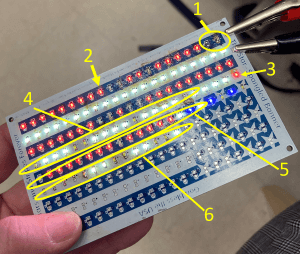
| 1 | First two, the LED’s kept sticking to the tip of my soldering iron. |
| 2 | Implemented my 3D-Printed Tweezer Base to hold LED’s in. |
| 3 | I am just getting old and couldn’t tell the difference between red and white LED’s. |
| 4 | Here I was trying to add a small amount of solder first, place the LED onto the solder mounds, and then “melt” the solder beneath. Some success, but not as good as with my 3D-Pirinted Tweezer Base. |
| 5 | Back to using my 3D-Printed Tweezer Base. |
| 6 | Tried using “Flux” paste. This was very difficult for me to use. I think I put too much of the paste onto the board. The LED’s were floating in so much of it that they were slipping out of position. The board was also now very sticky. |
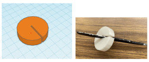
It was definitely beneficial using the microscope while surface-mount soldering. After getting mideay down the first row, I had an idea to design and 3D print something that could hold a pair of “curved, sharp-tipped” tweezers. It was my plan to have these tweezers hold the LED in place while I solder each end. I measured the thickness of the handle of the tweezers with callipers and went into TinCAD and designed a “Tweezer Base” that could hold my LED’s and resistors in place while I soldered them. The image below shows the .stl from TinkerCAD and the actual 3D printed Tweezer Base.
Through-Hole Soldering
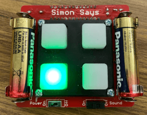
Early in the fall, for my final Fab Academy project, I had the idea to create a device/machine that could help my daughter (a D1 goalkeeper) to enhance her hand-eye coordination while in rehab after surgical knee reconstruction. It was suggested that I look at and work with different “buttons” to see how they could be utilized in this tyoe of project. I purchased a Simon Says Game from SpakFun and soldered it. I was wondering if it would be possible to “cannibalize” the buttons and use the same typs of program in my goalkeeper’s device. I wound up abandoning this idea, but it was fun playing with the Simon Game. My students enjoy it a lot!
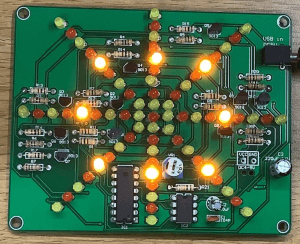
This semester, I asked my students to practice soldering by making a “Water Light Design” (I think it is supposed to be a snowflake?). In order to put the presentation together for them, I needed to solder it myself and take screenshots of each step as a guide for them. To test the circuit, I took the USB cord included in the kit and plugged it into both the circuit port and a power source, in this case, a computer. Once this was done, the pattern appeared, and the LEDs began flashing. Using the potentiometer, I was able to change the speed of the pattern. The image below shows the light pattern (quickly).
Learning Fusion 360
In late December, I was able to start doing Kevin Kennedy’s Learn Fusion 360 Tutorials. I was able to complete the following:
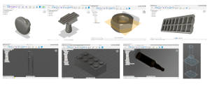
I learned how to:
Create folders;
-Change active units;
-Make a 2D sketch of an object; (In CAD software, a “sketch” is a 2D object that can be turned into a 3D shape).
-Extrude an object;
-Make a shell (make an object hollow);
-Make a rectangular prism.
-Insert and place points on a reference image;
-Make a fit point spline;
-Use the revolve feature (based on one half of the 2D design);
-Apply glass (or other material) appearance to the final 3D design.
-Use the line command;
-Create sketch fillets (as opposed to 3D fillets);
-How to create a sweep (with a drawn sketch profile).
-Create offset planes;
-Use the loft feature;
-Create threads.
-Use the sketch dimension;
-Extrude cut;
-Deploy the rectangular pattern feature.
-Use the polygon sketch;
-Create a midplane;
-Deploy the mirror feature;
-Use the hole feature.
-Use the “press pull”;
-Create text; and
-How to make a new body.
Wiring and “Programming” a 555 Chip
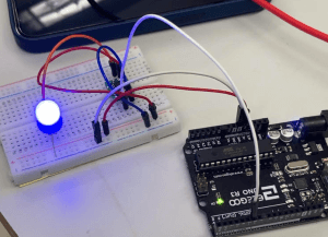
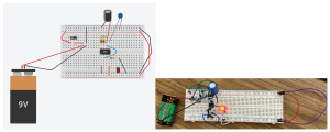
Tom Dubick taught us about 555 chips. He asked us to first assemble the following circuit in Tinkercad. My project can be found here. We were then given the actual materials to wire the circuit and cause the LED to blink. However, when I assembled the actual circuit, the light would not light up. After examining the same issues that others were having, we concluded that the capcitors were not functioning properly.
When going to take a picture of this circuit (many weeks later), I re-wired it again, and it actually worked! I quickly snapped a photo of it to capture it working. I feel that there was a wire loose on the day that we originally built them.
Introduction to KiCAD
With the KiCAD software, I was able to learn PCB and Schematic Design workflows. I completed lessons on creating schematics and checking energy values in the circuits. Hopefully, this will prove to be a good software for prototyping components in circuits.
Building an Ender3- Pro 3D Printer
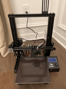
On January 19th, we were given Ender3 Pro 3D printers to assemble. Chuck Hellebyck’s video was of great benefit as the written instructions were minimal.
Wiring and “Programming” a 412 Chip
On January 26th, Tom Dubick taught us how to solder a 412 chip onto a board to create our own microcontroller. We used an Arduiono microcontroller to power and “program” the 412 chip.