Final Project Development–SpaceX Launch Alert
The following video summarizes my project overall.
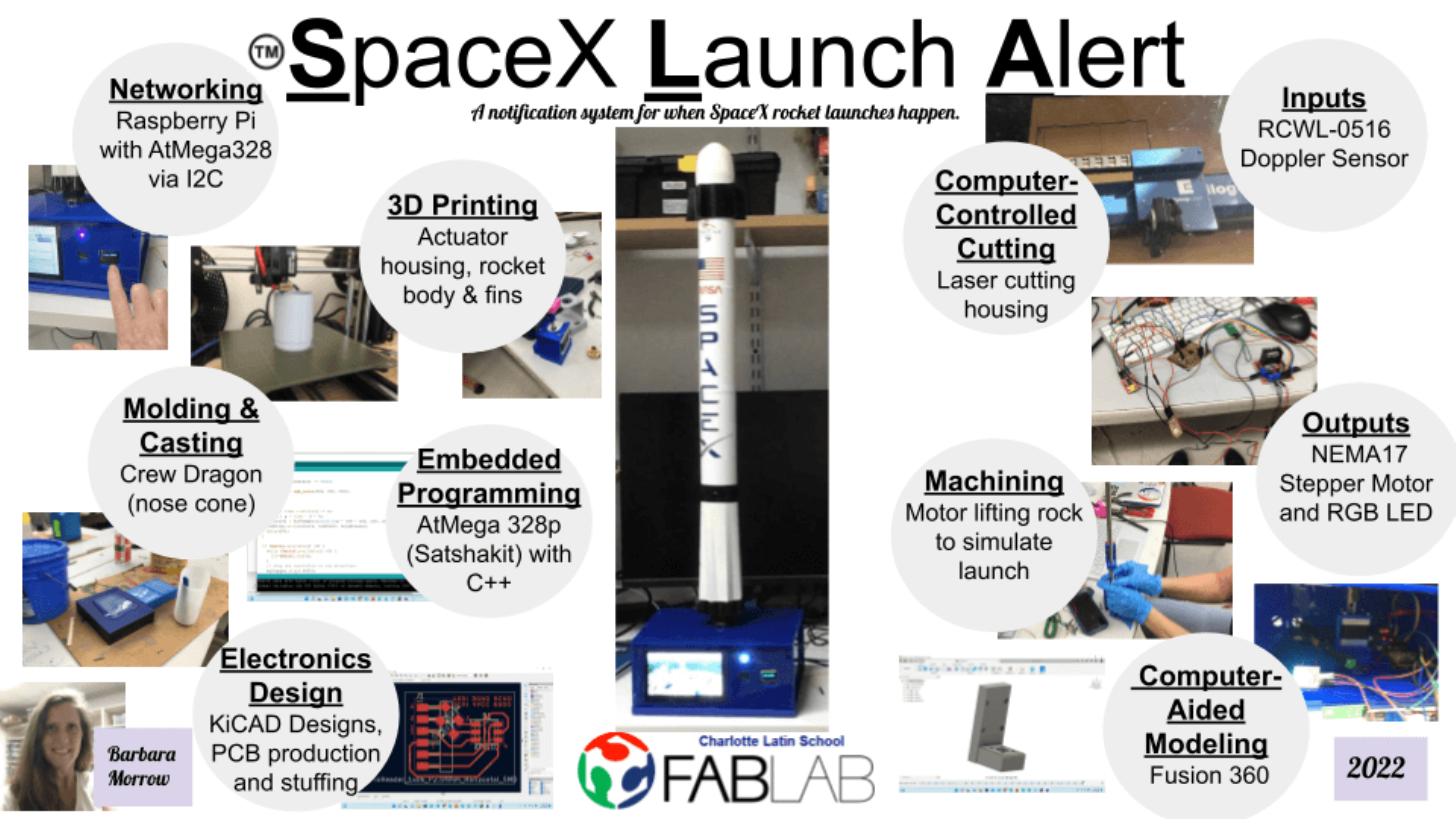
The following image shows the weekly skills that were used in developing my final project– the SpaceX Launch Alert (or SLA).
Benefit to the Community– Engineering Design Statement
This project is very personal to me, and the engineering design statement is very self-serving. The US Space programs and missions have always been very important to me. As a child, I loved watching the Space Shuttle launches (when I knew about them), and on the day that the Space Shuttle Challenger disaster occurred, I was home sick from school watching the launch.
Many years later, as a teacher, I felt that it was important for my students to know how the US Space programs (NASA) began– why they began, and the work that was done by space pioneers. In my science classes in middle school, my students were required to read the book, “October Sky” (Original Title: Rocket Boys) by Homer Hickam Jr. Each year, as my students read the novel, I would take them to Coalwood, WV for the annual “October Sky Festival”. While there, students would meet the characters from the book, and they would meet Homer Hickam Jr. We also took rockets that the students made and launched them at the same site as the “rocket boys” in the book.
The last year that I took students on this trip, an older woman approached us and asked if she could press the launch button. I immediately recognized her– it was Grace Corrigan, Christa McAuliffe’s mother. I recognized her from that horrible day of the Challenger disaster– the news footage of her as she watched the launch, and eventually realized she had lost her daughter. This moment (for me) in Coalwood, WV was one of the most monumental moments in my career and life. It was an honor meeting her.
Today, (many years later) I have grandchildren, and my grandsons are very interested in rockets and space. Our oldest grandson watched most of the 50th anniversary of the lunar landing footage with my husband, his Papa. When we can– and we know about them– we watch SpaceX launches with him. A SpaceX Alert System is needed to excite and inspire this young generation about space exploration.
On March 16th, I set up this page for documentation of my final project: a SpaceX Launch Alert System. It was my intention to utilize three Nema17 Stepper motors working together to raise the rocket into launch position and eventually simulate a launch
| Step # | What will happen |
|---|---|
| 1 | In a “normal state”, an RGB LED will be flashing through rainbow colors. |
| 2 | The PIR sensor (or RCWL-0516 sensor– written about by jdesbonnet) will detect whether my grandson is in the room. |
| 2a | If he is in the room, the RGB LED will change from the rainbow flashing to blue (or any one color). If the RGB LED is triggered to blue, the message “Hi there, James!” will be printed on an LCD screen. |
| 2b | If he is not in the room, the RGB LED will continue to flash through rainbow colors. |
| 3 | Twenty-four times per day (in the first fifteen seconds of every hour from the time the device is plugged in), using a free API– Rocket Launch API– JSON data will be “Scrubbed” and compiled. |
| 4 | When launch data is copied from RocketLaunch.Live, it can then be pasted into this site, called JSON Pretty Print. When “Load Data” is selected, the data will be parsed. |
| 5 | Using the requests library, requests can be run repeatedly as the time of launch approaches and run once after the launch is over (as a “reset” for the next launch). |
| 5a | If a SpaceX Launch is “detected”, the date, time and vehicle to be launched will be displayed on the LCD screen until the time of launch. |
| 5b | If a SpaceX Launch is “detected”, one hour before the launch, a message will be sent to the LCD screen asking “Are you there?”, and a “Y/N” selection option will be asked. If my grandson will be able to watch the launch, he will select “yes”. If “no” is selected, the next sequence will not occur. If “yes” is selected, a Vehicle Transporter carrying a “Falcon-like” rocket horizontally, will slowly crawl toward a vertical arm beginning one hour before the launch. If nothing is selected, If there is no response, a message will be sent to a parent’s cell phone stating that the launch can be watched at this site. |
| 6 | The modelrocket will be vertical and in the launch position. |
| 7 | At T minus 10 seconds, a small LCD screen will show the launch countdown. |
| 8 | At the actual launch time, the model rocket will loft off vertically. Once it reaches the highest point, the system will reset and reverse (stepper motor) directions. |
I have the system connected to a Raspberry Pi so that it can connect to Wi-Fi.
Who’s done what beforehand?
Nothing like this seems to exist. After extensive research, the only thing that alerts children of an upcoming launch is by signing up to receive them. For example, Kennedy Space Center has a “Receive Launch Alert” signup on their website.
There is also an app called Space Coast Launches.
Options like these are not conducive for the young children that we should be inspiring.
What will be designed?
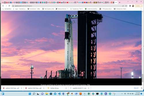
The following items were designed and made for this project. The parts that will be pre-made (not made by me) will be the Doppler radar sensor and the display screens (5” Touch Screen and OLED). It was my intention that the 5” Raspberry Pi touch screen could display the actual live SpaceX launch as the rocket itself launched. However, I had great difficulty making this happen (with the help of Christhoff Khouri). Mr. Khouri, who had experience with displaying videos with Raspberry Pi was familiar with OBX video streaming. The latest Raspberry Pi update eliminated OBX and now requires users to use VCL. I simply ran out of time to investigate this video streaming capability. Mr. Khouri showed me how to display an image of a Falcon 9 rocket launch on the 5” touch screen instead. It is my hope to have the live launches viewable on the 5” screen in iteration 2 of this project in the future.
Physical Components
| Item | Description |
|---|---|
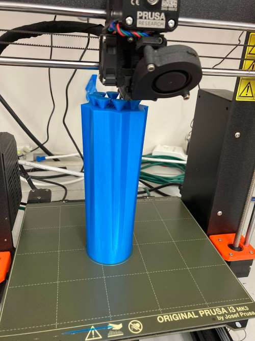
| Falcon9 Rocket | The entire rocket was designed in Fusion 360. The mmajority of the rocket– the body– was 3D printed using the Prusa 3D printers in the Charlotte Latin School Fab Lab. The nose cone– or crew dragon– of the SpaceX rocket was also designed in Fusion 360, milled out of wax with a Bantam desktop milling machine. It was then molded and casted in the Charlotte Latin School Fab Lab. |
| Vertical Rail/Unit | A 1/4” right-threaded steel rod was used with a coupling nut to create an actuator/carriage to lift the rocket vertically at the time of a SpaceX launch. |
| Electrical Housing Units | All programmers, PCB’s and sensors along with their wiring were contained and protected insided of a press-fit electrical housing usit thhat was designed in Corel Draw and laser cut out of 1/4” blue acylic/plexiglass in the Charlotte Latin School Fab Lab. |
| Motor Holder, Motor to Steel Rod Connector and Carriage/Actuator | These were designed in Fusion 360 and 3D printed on the Prusa 3D printers in the Charlotte Latin School Fab Lab. |
| SpaceX Branding | Vinyl-cut stickers were designed using Silhouette Studio and Cameo Vinyl Cutters in the Charlotte Latin School Fab Lab. |
Electrical Circuits
| Item | Description |
|---|---|
| PIR (or Doppler radar) motion detection w/RGB LED | I had planned to utilize the same RGB LED PCB I had used in previous weeks, but instead, I wound up designing a separate RGB LED breakout board so that I could incorporate it into a specific position with the elctrical housing/covering. |
| Launch Alert Status Determination | A Raspberry Pi 3 B+ and python code were used for this task. |
| Vertical Sequence (Stepper Motor turning 1/4”threaded rod) | This was controlled by an AtMega 328p (Satshakit) that communicated with a Raspberry Pi 3B+ via SPI. Intially, I had planned to have this communication between the two programmers occurring via I2C-2, but near the end of the project, it was easier to facilitate this through SPI communication. |
| Reverse/Reset | This was controlled by Arduino Code and python code simultaneously. |
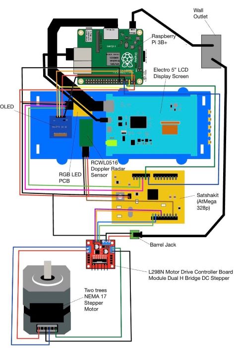
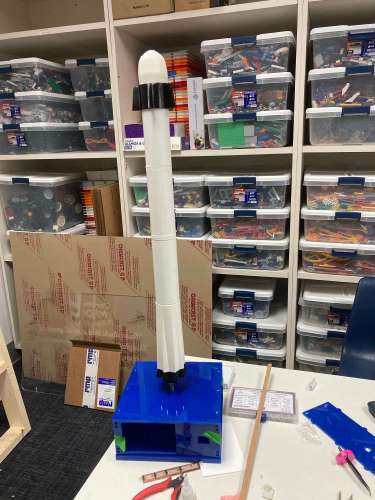
The SpaceX Launch Alert uses a Raspberry Pi connected to the Internet with python code to determine when the next SpaceX launch will occur. It then displays this information on a 1” OLED in the form of a countdown clock. At the exact time of launch, the rocket launch is simulated by the scaled Falcon 9 rocket on the 1/4” threaded rod. Ten seconds later, the Nema17 motor reverses its direction and “resets” the rocket for the next launch sequence.
The RGB LED (which is programmed with the AtMega 328p Satshakit) works in unison with the Doppler sensor. When no motion is detected, the RGB LED flashes through the colors of the rainbow, but when the Doppler sensor detects movement (within 7 meters), it flashes to white. It is my hope– in iteration 2 of this project– to have interactive questions when motion is detected (ie: “Is that you, _? or ?) The user can answer a series of questions that prepare them for viewing the launch.
The following image shows the final wiring of my project. (Drawn by B. Morrow)
Bill of Materials
| Item | Number of this Item Used | Cost |
|---|---|---|
| 0.96 Inch OLED I2C Display Module | 1 | ~$13.98/for 5 |
| ELECROW Raspberry Pi Touchscreen Monitor 5 inc | 1 | ~$55.99 |
| Songhe RCWL-0516 RCWL0516 Microwave Radar Sensor Module | 1 | ~6.79/for 5 |
| Twotrees Stepper Motor Nema 17 | 1 | ~$28.99/for 3 |
| Raspberry Pi 3 Model B+ Board | 1 | ~$275.99 |
| 1/4” x 24” x 36” Blue Plexiglass Sheet | 1 | ~$105.74 |
| 18-8 Stainless Steel Fully Threaded Rod, 1/4”-20 Thread Size, 24” | 1 | ~$22.44 |
| Coupling nut for 1/4 inch threaded rod | 1 | ~$12.29/for 10 |
| EDGELEC 120pcs Breadboard Jumper Wires | 1 | ~$7.99 |
| DotStar Addressable 5050 RGB LED w/ Integrated Driver | 1 | ~$4.50/for 10 |
| 5 volt power supply 3.5mm barrel connector | 1 | ~$10.99 |
| OUYZGIA MGN12H 500mm Linear Rail with Linear Bearing Block | 1 | ~$34.99 |
| SUNLU 250g PLA Filament 1.75mm, 3D Printer Filament | 1 | ~$42.99 |
| VIGRUE 570PCS Stainless Steel M3 Button Head Hex Socket Cap Screw Bolts | 1 | ~$18.99/whole set |
| Liberty.20Pcs Stainless Steel Folding Hinge 1 inch Cabinet Box Hinges | 4 | ~$10.98/for 10 |
The total cost for this project is $596.01. HOWEVER, I feel that this cost summation is not accurate. Numerous items on this list were things that were already in the Charlotte Latin School Fab Lab, and only a small portion of the roll of PLA was used. If I were to deduct the items that we already had in our possession (the Rapberry Pi, the acryic/plexiglass, the threaded rod, coupling nut, jumper wires, linear rail with linear bearing block, PLA filament, screw bolts and folding hinges), the total cost would be $74.66. Another thing to note, is that the cost of the Raspberry Pi at this point in time (in May/June 2022) is grossly inflated due to demands on the global supply chain.
Project Designing and Building Process
In this section, I explain the parts that were made, the processes used, what worked and didn’t work, and the future implications. I am not strong in coding, and four people– Dr. Adam Harris, Mr. Adam Durrett (colleague), Mr. Jeremy Profitt, and Mr. Christhoff Khouri. I mention their help in the appropriate sections.
During the Molding and Casting week (Week 10– March 22), I had the realization that molding my Falcon 9 rocket would not be the best use. I tried to change the molding and casting idea to make a silhouette of my husband and grandson, but the proportionality of this was not feasible. If I made the silhouette larger than 0.24”, my rocket would have to be made much larger that preferred. Discussions with colleague/classmate, Nidhie Dhiman produced the idea mold and cast the tires. SpaceX now transports their rockets to the launch pad in a different way than using a crawler (that NASA used to use). SpaceX now transports the rockets using a “Launcher Erecter Transporter” which is a glorified (and extremely large) flatbed truck that drives it on its side to the launch bed. Then, the erector hydraulically lifts the rocket into position.
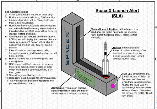
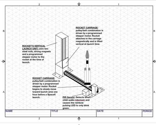
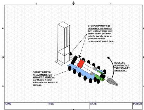
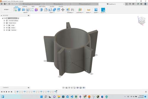
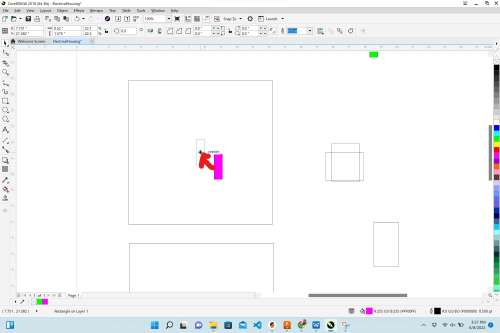
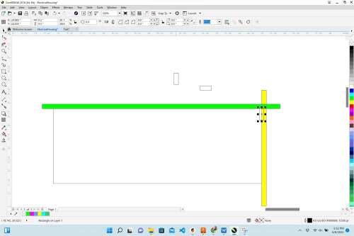
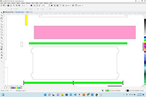
I decided to remove the horizontal movement of the rocket in my SpaceX Launch Alert device altogether. In its place, I will use a stepper motor to lift the rocket (starting one hour before the launch) from the horizontal position to the vertical position. Then, at launch time, the rocket would still be carried vertically by the vertical carriage system (using a stepper motor). The following is a rough image of the new design.
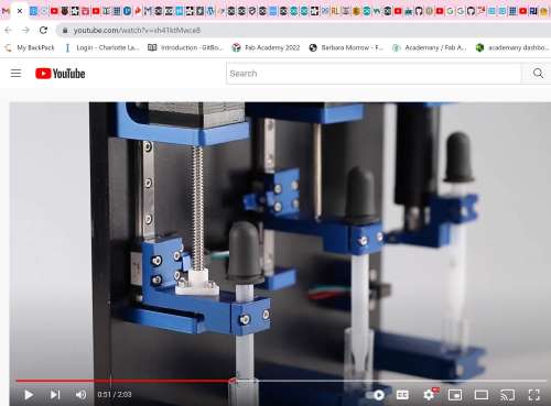
On April 2, I watched “DIY Pen Plotter with Automatic Tool Changer | Arduino based CNC Drawing Machine” which made me want to once again utilize a carriage in both the X direction and the Y direction. One major thing that this video did was use a smaller stepper motor to grasp drawing pens. I would like to implement this same type of mechanics as the Falcon 9 rocket is “grabbed” –or transferred– from the X-axis carriage to the Y-axis carriage.
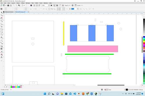
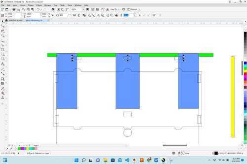
These images show the plans/designs used in this video that I had hoped to emulate in my final project.
| Image | Plan for Final Project |
|---|---|
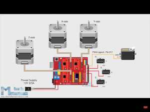 |
This is the way I would like to connect at least 2 (potentially 3 NEMA17 Stepper Motors). |
 |
This shows two NEMA17 Stepper Motors controlling movement in the the X and Y axes. |
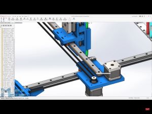 |
This shows a third NEMA17 Stepper Motor which I would not be using for movement in the Z axis. Instead, another NEMA17 (or smaller) Stepper Motor might be used to lift the Falcon 9 rocket from the horizontal position to the vertical (launch) position. |
 |
This shows the positions of limit switches, which I would also need in my final project. |
On April 25, I met with Dr. Adam Harris about how I will program my SpaceX Launch Alert System. In order to understand all that he shared with me, I had to do a little research.
In my final project, I will need to use an API (Application Programming Interface). To get a basic understand of what an API is, what it does and how it works, I watched this short video– called What is an API?. An API is the messenger that takes requests and tells a system what you what you want to do and then returns the response we want back to us.
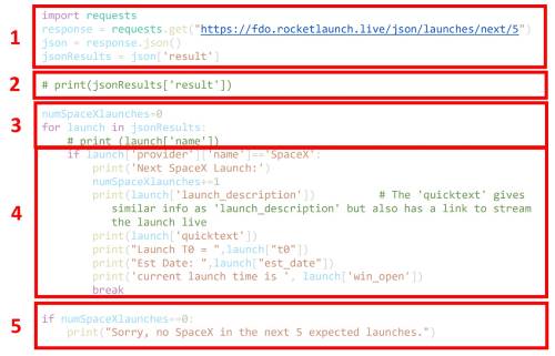
Dr. Harris was able to identify a good API (that hapens to also be free, and it requires no need for providing personal information). RocketLaunch.Live is a great API that makes the next five launches accessible freely using the following HTTP GET shortcut request. This request then provides the JSON data for launches (citation: Data by RocketLaunch.Live). JSON (Java Script Object Notation)
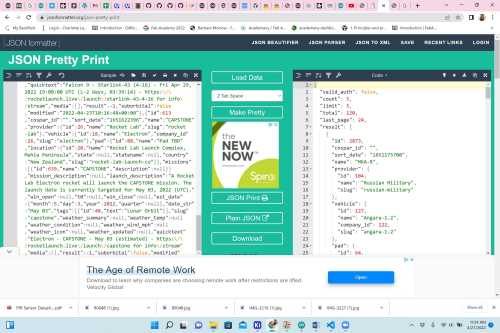
When launch data is copied from RocketLaunch.Live, it can be pasted into this site, called JSON Pretty Print (aka “the JSON Prettifier”).
https://fdo.rocketlaunch.live/json/launches/next/5
Once this site is clicked on, a plethora of launch information will appear (as shown below).
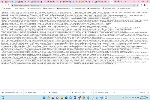
This data can be copied and placed in the “JSON Prettifier”, and when “Load Data” is selected, the data will be converted into manageable chunks.
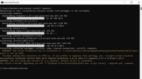
Using the requests library, requests can be run repeatedly as the time of launch approaches and run once after the launch is over (as a “reset” for the next launch). (I installed the requests library by running the command “pip install requests” in the Command Prompt on my computer).
Then, the following script (put together by Dr. Harris) can be used to constantly pull the data and “filtered” according to the type of launch that is approaching. In this case, the type of launch will be either SpaceX launch or non-SpaceX launch.
| Step | Description |
|---|---|
| 1 | This section of the code “pings” the “RocketLaunch.Live” site and targets the first five batches of information. |
| 2 | The JSON data is pulled off of the site. |
| 3 | The JSON data is filtered by the type of launch, and the number of SpaceX launches is determined. |
| 4 | If a SpaceX launch is determined, the message “Next SpaceX launch will be on __”. Also in this section of the code, the launch: type (ie. Falcon 9 or Falcon Heavy), date, location time (and launch window) will be collected only if the code deems there is a SpaceX launch coming up. |
| 5 | This is the last part of the “if… then” statement. If no SpaceX launch data is found in the JSON data, the following statement will be printed (ideally on an LCD screen): “Sorry, no SpaceX in the next 5 expected launches”. |
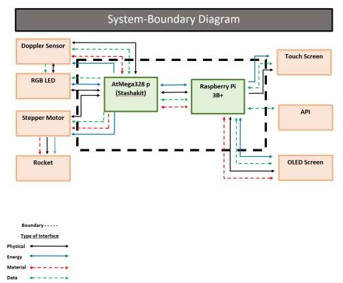
On May 24, I began designing the mechanical structure for my project. Since I had already designed an end piece for the end of the hosizontal rail, I decided I should work on the other end of the horizontal rail. This piece is critical in that it is the corner holding the horizontal and vertical rails together. I used Fusion 360, and obtained good callipers and began making measurements. I had found a 2’ horizontal rail in the Charlotte Latin School Fab Lab (while cleaning for the summer), and I was very excited about this because so far, I had only seen the 1’ ones. In answering all of the questions for last week (Applications and Implications), I decided to create a “Systems Boundary Diagram”. This wound up being very helpful as it clarified my thought process.
On May 25, I met with Dr. Tarance Fagan, and we duscussed the mechanics of my project and used the Systems Boundary Diagram to refine what I was planning to do. Then, on May 26, I met with Dr. Adam Harris and reviewed the same diagram. In this session, Dr. Harris and I made changes based on the realistic amount of time that I have left to develop a minimally viable product (or MVP). It was also in this discussion that we decided that the project would be simpler (and just as impactful) if we removed the horizontal movement of the rocket on the transport vehicle. Dr. Harris explained that this could always be added back into the project if time permitted, and I agreed.
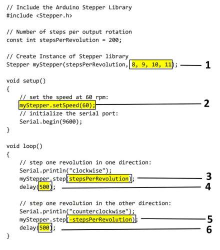
That evening, I decided to shift my attention to the electronics and coding section of the project. From Outputs week and Machine Design week, I knew how to get a stepper motot working. After the “MVP” discussion with Dr. Harris, I agreed to get the one motor functioning the way I needed it to. I measured the number of threads in one inch on the threaded steel rod. There were 13, and the steel rod was 14 ” long. I pulled up this code, and I began to modify it for my purpose. However, before modifying it, I made sure I got it working with my NEMA17 stepper motor.
| Number Above | How Code Was Changed |
|---|---|
| 1 | I changed these pins to 5, 6, 7, and 8 on the AtMega 328p for my code. |
| 2 | For my final speed, of the motor, I made this value 150 rpm. |
| 3 | This took a lot of experimentation to determine the steps per revolution. I first caluclated (very inaccurately), that I should have 36,400 steps based on the length of the threaded bar. After much testing, the value I settled on was 6000 here. Since the motor is going clockwise, the value needed to be positive. |
| 4 | This is the time (0.5 sec) that the motor “rests” when the rocket was at its highest point vertically. I wound up making this 10,000 (10 seconds). |
| 5 | Like part 3, I changed this value to 6000 to mirror the upward vertical distance. However, since the rocket would be going down this time, and to do this, the motor had to reverse and spin counterclockwise, the value needed to be -6000. |
| 6 | When testing, I made this value 3000. However, in my final code, this was taken out all together because the motor should be at rest after making one trek upward, and then down again. |
Electronics and Programmers
As Dr. Harris and I continued to discuss my project, we decided that a typical LCD screen (I was planning to use) might be one of the limiting factors since it was going to require a high number of pins. Dr. Fagan and I discussed potentially using two LCD screens, but Dr. Harris stated that it would be better to only use one that was connected to the Raspberry Pi Zero W. We (at the same time) found this article–Interfacing I2C LCD and 4 x 4 keypad with Raspberry Pi Zero W, and I began to investigate the possibility of using I2C with the Raspberry Pi Zero W and the LCD Screen. I found this site, which showed me how to identify the wires inside of a USB-USB cable. Since I would be using the four wires inside of the USB-USB cable, I prepared one for using in my project. (In the end, I wound up not needing this or using it.)
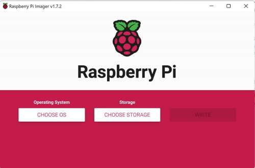
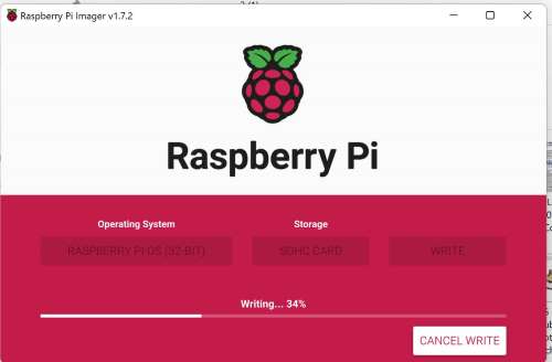
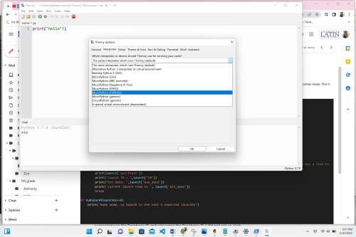
I also found and watched Raspberry Pi Zero W Setup with Serial/UART, which showed me how to connect the Raspberry Pi to UART. After communicating again with Dr. Harris again, he suggested I try using this video–The New Method to Setup Raspberry Pi Zero (2022 Tutorial– to get the Raspberyy Pi Zero W working from home. The images below show the Raspberry Pi Setup (left) and the Raspberry Pi OS (right).
| |
| |
|
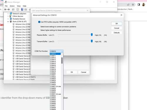
I was doing well until I had to enter the name of the Raspberry Pi and its IP address it had been given. After many searches, I couldn’t find the name of the Raspberry Pi Zero W I was given, and I also couldn’t determine the port number that was being used on my laptop. (Port issues have been profuse throughout the semester of Fab Academy for me.)
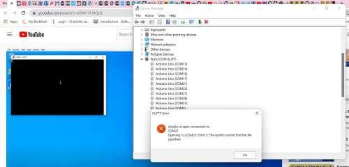
So I searched the Internet, and I found this site, by Maggie Marystone. She states to possibly downloaded the Fing app (which was pretty cool in showing all of the devices on our network at home). The following imgae shows my husband’s phone screen showing the devices on our home network.
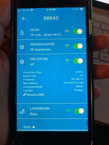
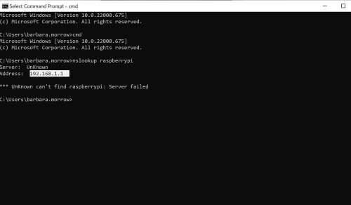
The problem was that it listed all of the devices on the 5G and 2.4g network. There were many devices connected with name “Generic”, and I couldn’t decipher which “Generic” was my Raspberry Pi. I tried to ping some of the “Generics”, but got only a graph display of the results and no luck with finding the IP address. There was one device that we suspected was the Raspberry Pi, and I tried it in the Command Prompt (shown below).
I also tried turning on “Alert me when state changes” of the device I suspected was the Raspberry Pi and uplugging the Raspberry Pi. I did not get an alert. With the COM Port ID issue, I also found this site.
I have started to set limits on how long I will allow myself to struggle before asking for help. Great time to implement it– in the end– but I had reached that limit. I decided to wait until I could meet with Dr. Harris in person in a couple of days. In the meantime, I wanted to read up on how to connect the LCD to my Raspberry Pi (eventually), and I found HOW TO SETUP AN LCD ON THE RASPBERRY PI AND PROGRAM IT WITH C.
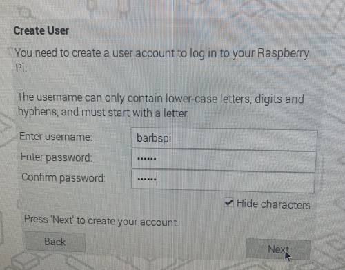
On Monday, May 31, I mentioned my struggles with the Raspberry Pi Zero W to colleague and friend, Mr. Adam Durrett (computer and electrical engineer). However, at this time, I was trying to get the Raspberry Pi Zero W to work on the Wi-Fi of Charlotte Latin’s campus. Adam decided to see if he could help to get it working. After about two hours, and with the help of the IT specialists at Charlotte Latin School, we were able to ID the Raspberry Pi Zero W and program it with the operating software (Raspberry Pi OS Using Raspberry Pi Imager) and SSH key loaded onto the ScanDisc.
However, we found the upload speed to be incredibly slow. So we went back to the Charlotte Latin Fab Lab and found another Raspberry Pi (a Raspberry Pi 3 B+) and began to program it in the same way. Since I am not as fluent with programming, Adam Durrett showed me the W3 Schools website to help with my commands. After a longer discussion, I asked Adam if using an ESP8266 Wi-Fi module would be better– instead of a Raspberry Pi. (I had just come across one as I was cleaning the Fab Lab). Since I was already numerous hours into the Raspberry Pi, and my plan was to get whatever device I was using to diplay results onto an some sort of screen, Adam thought we should give it a try. In a conversation with classmate, Aaron Logan, I had learned about an OLED Display Module With 0.96 Inch 128X64 Resolution,I2C Interface,Yellow&Blue Color,PCB Board that he aws using for his project and how Tom Dubick had odered some of them for the Fab Lab. It was particularly interesting to me since it is capable of running with I2C. Using the ESP8266 also allowed me to use the python script that Dr. Harris had written (shown below).
import requests
response = requests.get("https://fdo.rocketlaunch.live/json/launches/next/5")
json = response.json()
jsonResults = json['result']

# print(jsonResults['result'])

numSpaceXlaunches=0
for launch in jsonResults:
    # print (launch['name'])
    if launch['provider']['name']=='SpaceX':
        print('Next SpaceX Launch:')
        numSpaceXlaunches+=1
        print(launch['launch_description'])          # The 'quicktext' gives similar info as 'launch_description' but also has a link to stream the launch live
        print(launch['quicktext'])
        print("Launch T0 = ",launch["t0"])
        print("Est Date: ",launch["est_date"])
        print('current launch time is ', launch['win_open'])
        break

if numSpaceXlaunches==0:
    print("Womp womp, no SpaceX in the next 5 expected launches")
To get the ESP8266 working, Adam Durrett and I used Getting started with MicroPython on the ESP8266, and from this site, we used the following two commands:
esptool.py --port /dev/tty.usbserial-141140 erase_flash
and
esptool.py --port dev/tty.usbserial-141140 --baud 460800 write_flash --flash_size=detect 0 Users/barbara.morrow/esp8266-20220117-v1.18.bin
The following images show the python configuration with the ESP8266 (top) and the ESP8266 functioning with Dr. Harris’s script (bottom).
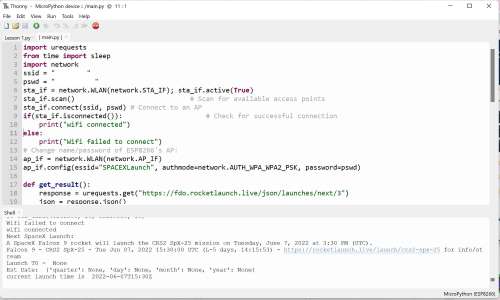
Once I got the ESP8266 running (using Thonny), I was so excited to see the script from Dr. Harris working!
The next thing I did was get the OLED working with the ESP8266. To do this, I followed the steps in ESP8266 0.96 inch OLED Display with Arduino IDE.
I also watched HOWTO Raspberry PI + OLED Display, and then I used Python Wiring, which I felt was reputable. This tutorial prompted me to continue through its next two pages– “Python Setup” and “Circuit Python Usage”.
Connecting Raspberry Pi to Internet with Ethernet Cord
In setting up the Raspberry Pi and connecting it to the Internet using an ethernet cord, I viewed How to Setup Raspberry Pi 3 Model B+ (since the one I had is a 3B+). Once I had the Raspberry Pi connected, I was able to use the Thonny IDE to launch Dr. Harris’s code. The following video shows my initial work with the Raspberry Pi.
As I used it and tested it, I kept getting low voltage messages on the lower right corner of the screen. In the middle of using it, I learned that plugging a Raspberry Pi into a computer USB port does not provide enough power (thanks to Dr. Harris), and I had to get a separate 5V power supply. Once I swicthed to using it, the Raspberry Pi did not have anymore issues. The following video shows my testing of Dr. Harris’s original code– which I eventaully get working. As it turned out, the incorrect and low voltage was prohibiting the Raspberry Pi from connecting to the Internet and functioning properly.
Connecting Raspberry Pi to Home WiFi
In order to work with the Raspberry Pi from my home, I had to connect it to either an ethernet cord or configure it to my home’s wifi. All of our ethernet cords are situated behind televisions mounted on the walls of home, and they were not long enough to reach my workspace. Also, the Raspberry Pi would have to be configured for wifi at my grandson’s house. To do this, I used “How To Configure WiFi on Raspberry Pi: Step By Step Tutorial”. After all of the trouble I had with trying to get the Raspberry Pi Zero to connect to my wifi, I was very worried that this would again be an arduous process. However, the steps in this tutorial made it feasible for me to understand what I was doing.
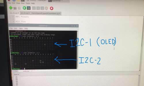
While I was setting up the Raspberry Pi, I decided to go ahead and intialize the SPI, I2C-1 and I2C-2. To do this, I used Enable I2C Bus On The Raspberry Pi. The following images shows my screen when I did this.
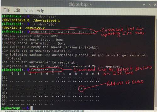
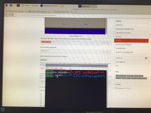
In order to set up the second I2C on the Raspberry Pi, I used Raspberry Pi SPI and I2C Tutorial. At this point, the plan was to connect the OLED to the Raspberry Pi using I2C-1 and connect the AtMega 328p to the Raspberry Pi using I2C-2. In the end, I wound up using SPI for the AtMega 328p. More on that later.
Installing libraries
Now that the Raspberry Pi was set up, I needed to install a couple of libraries– the BCM2835 and Fonts Library (ePaper). I found the first command for installing the BCM2835 library a bit confusing, so I went to this site, and I was successful. I then moved on the the ePaper library for fonts, and went to this site.
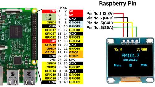
The following image shows how I wired the Raspberry Pi to the OLED.
The following code is the Raspberry Pi code that Dr. Harris wrote, and I used for my project.
from datetime import datetime, timedelta
from pickle import TRUE
from threading import Timer
from datetime import datetime, time, timedelta
from threading import Timer
from time import sleep
import serial
import os
import sys
import time
import requests # for rocket website API
import board
import digitalio
from PIL import Image, ImageDraw, ImageFont
import adafruit_ssd1306


####### Global Variables
debug = False #<-- Set to True so you don't make too many requests from the server. False when you are ready to run for real
launchDate = None #Create a global variable to hold the launch date. (Not the best way to handle this, but simple and effective...)

# Define the Reset Pin
oled_reset = digitalio.DigitalInOut(board.D4)

# Change these
# to the right size for your display!
WIDTH = 128
HEIGHT = 32  # Change to 64 if needed
BORDER = 5

# Use for I2C.
i2c = board.I2C()
oled = adafruit_ssd1306.SSD1306_I2C(WIDTH, HEIGHT, i2c, addr=0x3C, reset=oled_reset)

# Create blank image for drawing.
# Make sure to create image with mode '1' for 1-bit color.
image = Image.new("1", (oled.width, oled.height))

# Get drawing object to draw on image.
draw = ImageDraw.Draw(image)

# Load default font.
font = ImageFont.load_default()

# function to get difference in seconds between 2 dates
def dateDiffInSeconds(date1, date2):
  timedelta = date2 - date1
  return timedelta.days * 24 * 3600 + timedelta.seconds

# out days, hours, minutes, and seconds
def daysHoursMinutesSecondsFromSeconds(seconds):
minutes, seconds = divmod(seconds, 60)
hours, minutes = divmod(minutes, 60)
days, hours = divmod(hours, 24)
return (days, hours, minutes, seconds)


#function to request next 5 rocket launches in the world, strip out the next one from SpaceX
def getLaunchList():
    response = requests.get("https://fdo.rocketlaunch.live/json/launches/next/5")
    json = response.json()
    jsonResults = json['result']

    # print(jsonResults['result'])

    numSpaceXlaunches=0
    for launch in jsonResults:
        # print (launch['name'])
        if not numSpaceXlaunches and launch['provider']['name']=='SpaceX':
            numSpaceXlaunches+=1
           # print('Next SpaceX Launch:')
            #print(launch['launch_description']+"\n")          # The 'quicktext' gives similar info as 'launch_description' but also has a link to stream the launch live

            # print(launch['quicktext'])
            quicktextDateString = launch['quicktext']
            launchDateString = quicktextDateString.split(' - ')[2]  #split the quicktext description to only return the launch date
            launchDate = launchDateString.split(' U')[0]
            # print("Launch T0 = ",launch["t0"])
            # print("Est Date: ",launch["est_date"])
            # print('current launch time is ', launch['win_open'])
            return (launchDate)
            break

    if numSpaceXlaunches==0:
        launchDate = None
        print("Womp womp, no SpaceX in the next 5 expected launches")
        return (None)


#This function is used for testing so you don't overrun the rocket server
def FAKEgetLaunchList():
    x=datetime.today()
    x = x.replace(day=x.day, hour=x.hour, minute=x.minute, second=x.second)+ timedelta(seconds=30) # TESTING PURPOSES
    launchDate = None #x.strftime('%a %b %d, %Y %H:%M:%S')
    #print ("FAKE launch date = " +launchDate)
    return (launchDate)

def printToLCD(text):
        # Draw Some Text
        #text = "Hello World!"
        oled.fill(0)
        draw.rectangle((0, 0, oled.width, oled.height), outline=255, fill=0)
        (font_width, font_height) = font.getsize(text)
        draw.text(
            (oled.width // 2 - font_width // 2, oled.height // 2 - font_height // 2),
            text,
            font=font,
            fill=255,
        )

        # Display image
        oled.image(image)
        oled.show()

# main funciton here
def main():

    #Flow of this code:
    # 0. Setup I2C LCD for Rpi
    # 1. Start a "forever loop" (while(1))
    # 2. As soon as this script runs, get the next launch date
    # 3. Set up the next time to update the launch date to 1am the next day
    # 4. Display the countdown
    # 5. Once countdown ends, delay for an hour and then check for next launch

    # Step 0:

    # Use for SPI
    # spi = board.SPI()
    # oled_cs = digitalio.DigitalInOut(board.D5)
    # oled_dc = digitalio.DigitalInOut(board.D6)
    # oled = adafruit_ssd1306.SSD1306_SPI(WIDTH, HEIGHT, spi, oled_dc, oled_reset, oled_cs)

    # Clear display.
    oled.fill(0)
    oled.show()

    # Draw a white background
    draw.rectangle((0, 0, oled.width, oled.height), outline=255, fill=255)

    # Draw a smaller inner rectangle
    draw.rectangle(
        (BORDER, BORDER, oled.width - BORDER - 1, oled.height - BORDER - 1),
        outline=0,
        fill=0,
    )


    # Step 1:

    if __name__ == '__main__':
        ser = serial.Serial('/dev/ttyACM0', 9600, timeout=1)
        ser.reset_input_buffer()

    while True:
        ser.reset_input_buffer()


        # Step 2:
        if(debug):
            launchDate = FAKEgetLaunchList()
            printToLCD("loop stated")
        else:
            launchDate = getLaunchList()

        # Set up next time to get next rocket launch from website API
        x=datetime.today()


        #  Step 3
        if(debug):
            y = x.replace(day=x.day, hour=x.hour, minute=x.minute, second=x.second)+ timedelta(seconds=30) # TESTING PURPOSES
            #print("today is "+str(x))
            delta_t=y-x #get the difference from now until the next time we want to run the check of launches
            t = Timer(delta_t.total_seconds(), FAKEgetLaunchList) #<-- use this so as not to make too many requests from the server

        else:
            y = x.replace(day=x.day, hour=1, minute=0, second=0, microsecond=0) + timedelta(days=1) #at 1:00am 1 day from now
            delta_t=y-x #get the difference from now until the next time we want to run the check of launches
            t = Timer(delta_t.total_seconds(), getLaunchList) # In that number of seconds, run the function named "getLaunchList"


        delta_t=y-x #get the difference from now until the next time we want to run the check of launches
        t.start()  # Actually start this thread in the background
       # print("checking next launch at "+str(y))


        #  Step 4:
        if launchDate == None:
            printToLCD("No launches scheduled") #<-- Replace with Display code
            sleep(86400) #sleep for 24 hours = 86400 seconds
        else:
        # Now set up the countdown timer to the next launch. Reference: https://gist.github.com/morion4000/3866374?permalink_comment_id=2852932#gistcomment-2852932
            dateFormat = '%a %b %d, %Y %H:%M:%S'      # Tell python how launch date is formatted useing the symbols described here: https://www.geeksforgeeks.org/how-to-format-date-using-strftime-in-python/
            req = datetime.strptime(launchDate, dateFormat)
            now = datetime.now()
            #print(str(req) + " now = "+ str(now))
            while req>now:
                #This is where you would write to your display
                printToLCD("%dd %dh %dm %ds" % daysHoursMinutesSecondsFromSeconds(dateDiffInSeconds(now, req)))
                sleep(1)
                now = datetime.now()

            printToLCD("we have liftoff!") #<-- Replace with Display code

            ser.write("1")

            #print("sleep for an hour after liftoff, then start over")
            sleep(3600) #  delay for an hour then get next launch time from the server


if __name__ == "__main__":
    main()
This video shows me running Dr. Harris’s code on the Raspberry Pi; the Raspberry Pi was connected to the OLED using I2C-1.
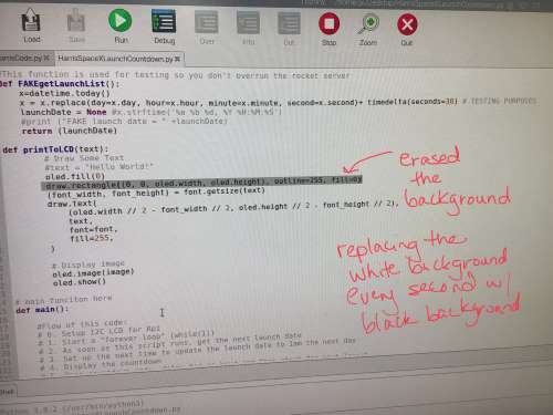
In this video, you will notice that some of the numbers became blurry over time. The numbers did not seem to be clearing as they changed with the time. I sought the help of Mr. Jeremy Proffitt, who showed me how to add a black screen between each ticking second. To do this, we had to modify the following line (In line 101) of Dr. Harris’s code:
draw.rectangle((0, 0, oled.width, oled.height), outline=255, fill=0)
This image shows where the code was changed (in line 101).
Preparing Satshakit (Uploading Bootloader)
After several discussions with Dr. Harris, I decided that using a Satshakit (AtMega328p) would be the best options for me because it had more pins and memory than an ATTiny 1614 chip. I obtained a Satshakit that was already soldered in the Charlotte Latin School Fab Lab, but I was unsure of whether it was programmed or able to function. To set up the Satshakit, I went to this page.
The first thing I had to do was upload a bootloader onto the Satshakit and initiate the I/O pins. The following images show me doing this.
Now that the bootloader was successfully on the Satshakit, I could use it like a “straight-up” arduino. When wiring devices to the Satshkit, I relied heavily on the following pinout.
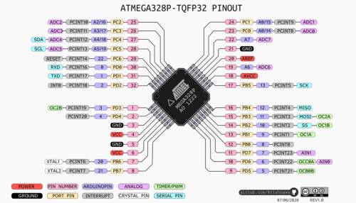
I was now ready to wire the Doppler sensor, RGB LED and Nema17 stepper motor to it.
Doppler Motion Sensor With Satshkit
Now that I had the Satshakit set up, I was ready to test it out with the Doppler sensor. The Doppler sensor only uses three pins– just like the PIR sensor I had been using up the this point, and I was thankful that I had done the work with the PIR sensor before trying out the Doppler sensor. The following image shows the RCWL-0516 (Doppler Sensor that I used).
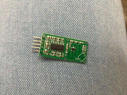
Since I knew the RCWL-0516 was going to be connected to the ATMega 328p (Stashakit), I used the article–RCWL-0516 Doppler Radar Sensor Interfacing with Arduino to help me connect it and understand it. I also used the code from this site (shown below).
int flg = 0;
int Sensor = 12;
int LED = 3;

void setup() {
  Serial.begin(9600);
  pinMode (Sensor, INPUT);
  pinMode (LED, OUTPUT);
  Serial.println("Waiting for motion");
}

void loop() {
     int val = digitalRead(Sensor); //Read Pin as input
     if((val > 0) && (flg==0))
     {
        digitalWrite(LED, HIGH);
        Serial.println("Motion Detected");
        flg = 1;
     }
     if(val == 0)
     {
        digitalWrite(LED, LOW);
        Serial.println("NO Motion");
        flg = 0;
     }
}
I was pleased that the RCWL-0516 was so easy to use. I connected the Doppler sensor to the Satshakit with its data pin on pin 12 of the Satshakit. When motion was detected, the words “Motion Detected” should appear, and when there was no motions, the words “No Motion” should appear. The following video shows the Doppler sensor working with the Satshakit.
Stepper Motor Working With Satshakit
I was now ready to wire my NEMA17 Stepper motor to the Satshakit, and I decided to use pins 5, 6, 7 and 8 in the following code.
#include <Stepper.h>

const int stepsPerRevolution = 200;  // change this to fit the number of steps per revolution
// for your motor

// initialize the stepper library on pins 5 through 8:
Stepper myStepper(stepsPerRevolution 5, 6, 7, 8);

void setup() {
  // set the speed at 60 rpm:
  myStepper.setSpeed(60);
  // initialize the serial port:
  Serial.begin(9600);
}

void loop() {
  // step one revolution  in one direction:
  Serial.println("clockwise");
  myStepper.step(stepsPerRevolution);
  delay(500);

  // step one revolution in the other direction:
  Serial.println("counterclockwise");
  myStepper.step(-stepsPerRevolution);
  delay(500);
}
The following videos show me working with the stepper motor. In the first part of the video, the stepper motor does not function properly. Having experience working with it at this point, I realized that there was a problem with the wiring. I decided to remove the carriage/actuator from it and troubleshoot. Without the carriage and actuator, you can’t see their movement up and down, but you can still see that the motor spins clockwise.
I then added the Doppler sensor with the stepper motor, and this imgae shows how they were wired to the Satshakit.
This is the combined code I used with the Doppler sensor and the stepper motor together.
// Include the Arduino Stepper Library
#include <Stepper.h>

// Number of steps per output rotation
const int stepsPerRevolution = 200;

// Create Instance of Stepper library
Stepper myStepper(stepsPerRevolution, 5,6,7,8);

int flg = 0;
int Sensor = 12;
int LED = 3;

void setup()
{
  Serial.begin(9600);
  pinMode (Sensor, INPUT);
  pinMode (LED, OUTPUT);
  Serial.println("Waiting for motion");
  // set the speed at 60 rpm:
  myStepper.setSpeed(150);
  // initialize the serial port:

}

void loop()
{
       int val = digitalRead(Sensor); //Read Pin as input
     if((val > 0) && (flg==0))
     {
        digitalWrite(LED, HIGH);
        Serial.println("Motion Detected");
        flg = 1;
     }
     if(val == 0)
     {
        digitalWrite(LED, LOW);
        Serial.println("NO Motion");
        flg = 0;
     }
  // step one revolution in one direction:
  delay(3000);
  // step one revolution in one direction:
  Serial.println("clockwise");
  myStepper.step(-8300);
  delay(4000);

  // step one revolution in the other direction:
  Serial.println("counterclockwise");
  myStepper.step(8300);
  delay(4000);
}
When I ran this code, I found that opening the serial monitor to see the Doppler working caused the motor to stop running. This was going to need to be tweaked. I knew I did not need the serial monitor to tell me the direction of the motor, or to tell me if there was motion or not, and I planned to remove the serial portions of the code. In the end, it would be the RGB LED working with the Doppler sensor, changing color when motion was detected. I decided to move on to adding the RGB LED into the project now.
Determining Address of AtMega328p
At this point, it was my intention to use the I2C-2 bus of the Raspberry Pi to control the motor which would cause the rocket to raise at the same time as a SpaceX rocket. I tried to use How to Work with I2C Communication in Raspberry Pi, but I could not get the address of the AtMega328p from this method because there were multiple things showing up in the grid.
Aaron Logan pointed me to this video–Find I2C Addresses on Arduino (I2C Scanner), where I was able to use the following code to determine the address of the ATMega 328p (Satshakit) when I connected it to a regular Arduino using I2C.
#include <Wire.h>

void setup()
{
  Wire.begin();
  Serial.begin(9600);
}

void loop()
{
  int error;
  int address;
  int devices = 0;

  Serial.println("Devices found:");

  for(address = 1; address < 127; address++ )
 {
    Wire.beginTransmission(address);
    error = Wire.endTransmission();

    if (error == 0)
    {Serial.print("0x");
    if (address<16)
      Serial.print("0");
    Serial.println(address,HEX);
    devices++;
    }
    else if (error==4)
    {
      Serial.print("Unknown error at address 0x");
      if (address<16)
        Serial.print("0");
      Serial.println(address,HEX);
    }
  }
    if (devices == 0)
      Serial.println("No I2C devices found");

    delay(5000);
}
From this, I was able to gather that the address of the AtMega328p is 0x05 as this is what was displayed in the serial monitor. Note: In the end, this wound up being a moot discovery because I switched to connecting the Satshakit to the Raspberry Pi 3B+ using SPI communication.
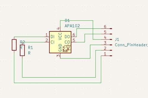
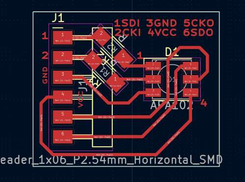
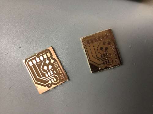
I decided to make a breakout board that contained only the RGB LED (and two 499-Ohm resistors between the pins 1 and 2 and their respective headers). I made two of these breakout boards (images of schematic and PCB below).
 |
 |
|---|---|
 |
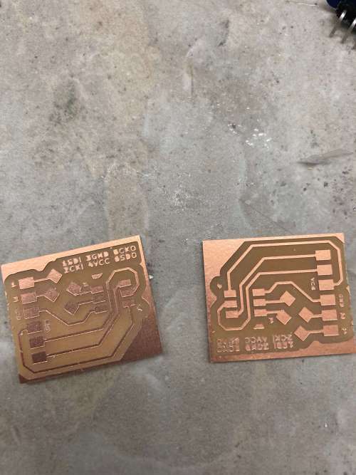 |
After talking with classmate, Aaron Logan, I also made a common GND and commone VCC board. The following video is a timelapse of me stuffing both of these boards.
Once I had the common GND and common VCC board stuffed, I was able to test it with an MVP board used in a previous week. This MVP PCB had an ATTiny 412 chip and a basic blink code was already loaded onto it. The following video shows this board functioning properly.
I wound up not using the common GND and common VCC board. When I first attempted to wire the Satshakit to this board with all of the devices, I was getting errors, and a portion of the board was getting hot to the touch. I did not want to risk something happening to my Satshakit so close to the project presentation deadline. I would like to get this board working on future iterations though.
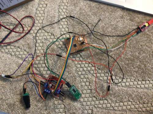
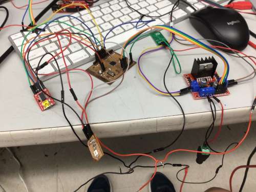
Now that I had the RGB LED breakout boards created, I wired up the all of the elctronics and began testing everything together. The following image shows how the NEM17 stepper motor, the Doppler sensor and the RGB LED were all wired to the Satshakit.
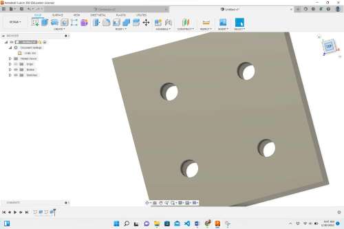
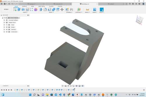
Designing the Actuator/Carriage, Connector and Motor-Mount in Fusion 360
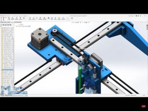
Before designing the carriage that would lift the rocket at the specified launch time, I did extensive research in designs that already existed. I wound up using these sites to generate ideas for the mechanism that would cause the rocket to lift vertically on the threaded rod: Low cost Linear actuator for CNC Machines and alike!, OpenBuilds V-Slot™ Linear Actuators, Linear actuator concept for CNC machines, 3D printed Rack and Pinion Actuator, and Making A Powerful Linear Actuator. However, it was this site–Thomson Tech Tips: Stepper Motor Linear Actuator Assembly Configurations– that inspired my design for my rocket’s linear actuator.
I had already found a 1/4” brass coupling nut in the Charlotte Latin School Fab Lab (when breaking down old students projects), I set out to design my own version of this in Fusion 360. The following steps were used to design my linear actuator/carriage.
| Image | What Was Done Here |
|---|---|
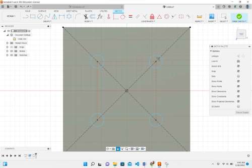 |
I began by making a square that was 25 mm x 25 mm. The brass coupling nut had four screw holes on it. I used callipers to measure their position within the square. I also used the callipers to measure the diameter of the scre holes and the height of the brass coupling nut. The height of the brass coupling nut was roughly 11 mm, so I extruded this whol square 11 mm. |
 |
After placing the four scre holes in the base square of the carriage, I selected all of them and extruded them -11 mm. This formed screw holes in the base. (After testing the carriage and finding it to be very weak where the screw holes were, I wound up making the screw holes 1 mm larger in diameter, giving the screws room for slight movement). |
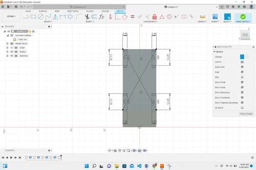 |
On the back side of the actuator, I added a rectangle that was 8 mm x 27 mm, and I extruded this upward to a height of 58.5 mm. In order to fasten to the ball-bearing carriage on the linear rail, I used the callipers to measure where screws could fasten into it. Using architecture lines, I was able to place the screw holes shown in the positions here. Once the screw holes were placed, I extruded them -8 mm to form holes. Again, to reduce stresses of the screws, I made the holes an additional 1 mm in diameter. |
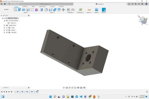 |
I measured the diameter of the breass nut (with callipers) to be roughly 10 mm, and I placed a circle with a diameter of 10.5 mm on the top surface of the lower portion of the design. Using architecture lines, I was able to find the exact center of this portion of the carriage, and placed the center of the circle there. Then, I extuded that circle -11 mm to form the hole for the brass coupling nut. |
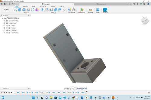 |
Once all of the screw holes and hole for the coupling nut had been created, I used the fillet tool to round the exterior corners. This image shows the completed carriage for the actuator, and I 3D printed it. |
I wound up having two disasters with this unit when transporting the vertical rail with actuator to and from the Charlotte Latin School Fab Lab. Twice, the carriage broke, but these incidents wound up showing me where I needed to reinforce it. The image below shows the breakage after one of these incidents.
To reinforce these designs, I doubled the infill when 3D printing from 20% to 40%. And, as a reminder, I also widened the screw holes by 1 mm in diameter. This widening also helped the screws to line up well when attaching them to the carriage on the linear rail.
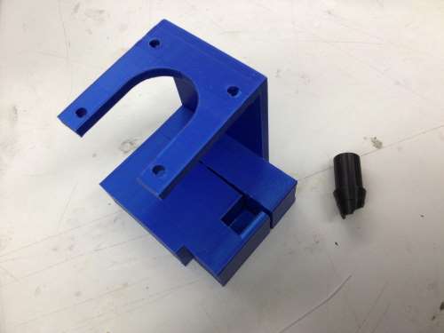
Next, I had to design the connector between the rod on the NEMA17 Stepper Motor and the 1/4” steel threaded rod. I needed this connector to be as tught and sturdy as possible and not allow any rotational movement between the motor’s rod and the steel threaded rod. Examining the small rod extruding from the NEMA 17 stepper motor (on the Z axis) up close, I noticed that one side of it was flat. Uisng callipers, I measured all of the dimensions of the small motor rod and the threaded steel rod. The following images and descriptions show how I designed the connector in Fusion 360.
| Image | What Was Done Here |
|---|---|
 |
I made a small circle with a radius of 2.5 mm. Then, I created an offset plane that was 25 mm away from the first on. I drew a center circle with a diameter of 10 mm and used the lofting tool to conenct the two ends together. |
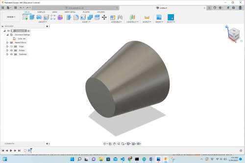
 |
I used the shell tool (with a thickness of 2 mm) to hollow out the center. Using an architecture line, I add a line where the flat side of the motor’s rod would match up. |
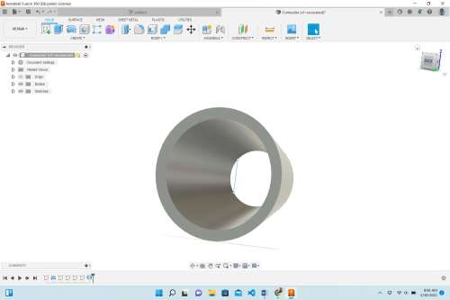
 |
Once I knew this line was in the correct place, I made it an actual line, and with the area/face that was created, I extruded that portion 5 mm. |
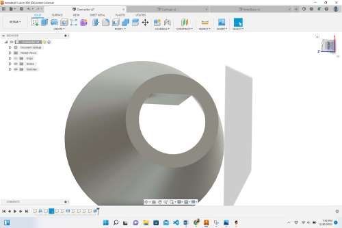
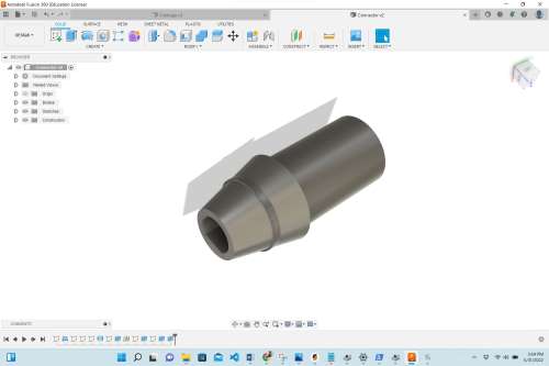 |
This shows the final connector. I added a 2 mm solid area where the two metal rods would touch if not there. I also added ticker areas around the center to make the contact area more sturdy. These stronger areas were add after the two “disasters” mentioned above where the device was dropped twice when transporting it to and from the Fab Lab. When I 3D printed this connector, I also made the infill 40% to make it stronger, and I 3D printed five of them in total in case this accident happened again. |
As I did testing with the motor and the carriage, I noticed that the motor moved along the table quite a bit when it was running. I needed to design some sort of mount that could stabilize it and prevent movement. The screw holes in the top of the NEMA17 stepper motor could be utilized to stabilize the motor vibrations.
| Image | What Was Done Here |
|---|---|
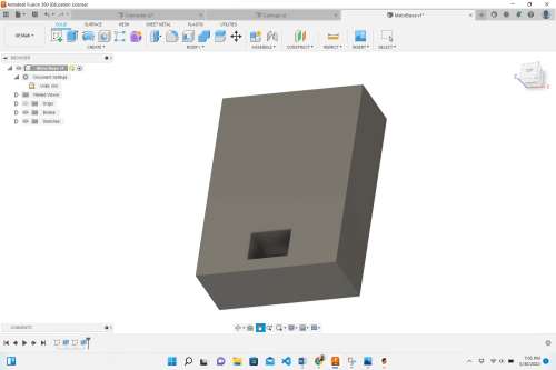 |
I started off by making a rectangle with dimesions of 42 mm x 58 mm. I extruded it 20 mm and placed a rectangle with dimensions of 12 mm x 8.7 mm on the top of it. I then extruded this rectangle -14 mm. This would give the rectangular rail the ability to slide into the rectangular hole without going too far/all the way through it. |
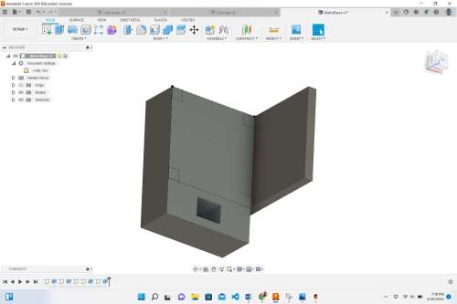 |
On one side of the previously-made block, I made a 4 mm x 42 mm rectangle and extruded it 55 mm. This height was 4 mm beyond the height of the NEM17 stepper motors. I measured the distance of the screw holes and also placed construction lines/rectangles where the center of the screw holes should go. |
 |
I created an offset plane on one inside plane of the newly extruded rectangle, and placed a rectangle that was 4 mm x 42 mm. I then extruded this rectangle 46 mm to create an overhang. I also placed the circles for the screw holes and extruded them -4 mm. |
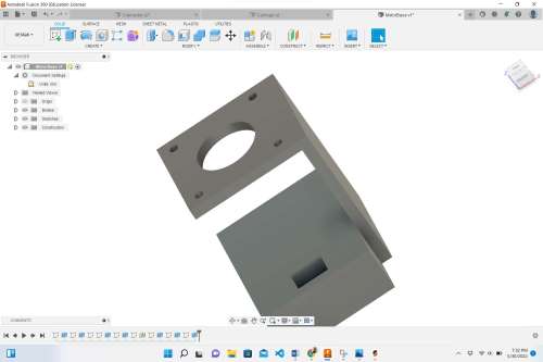
 |
This is the final motor mount. I added a circle on the top with a diameter of 22 mm and created two parallel tangent lines that extended to the edge of the open side. I extruded the areas made by both the circle and the tangent lines -4 mm. To balance out and stabilize the design even more, I added a 4 mm x 42 mm rectangle of the front side and extruded it 18 mm. I added two screw holes symmetrically to each side of the rectangular rail hole so that the entire motor mount could be screwed into the electrical housing/encasement. |
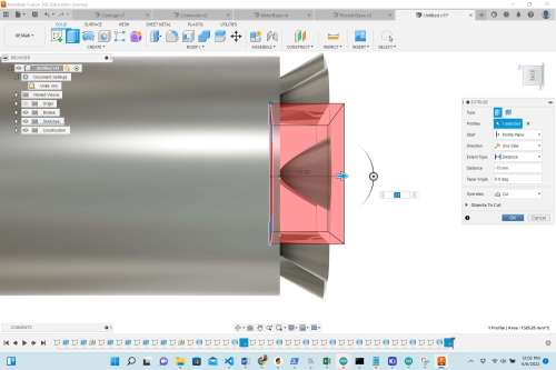
Designing the Falcon 9 Rocket in Fusion 360
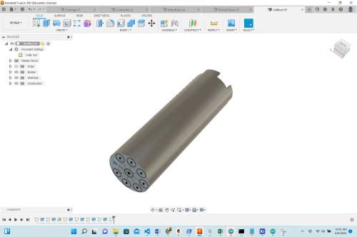
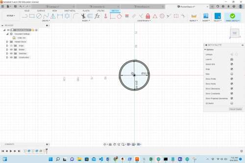
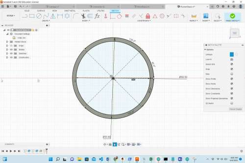
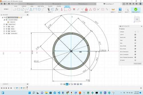
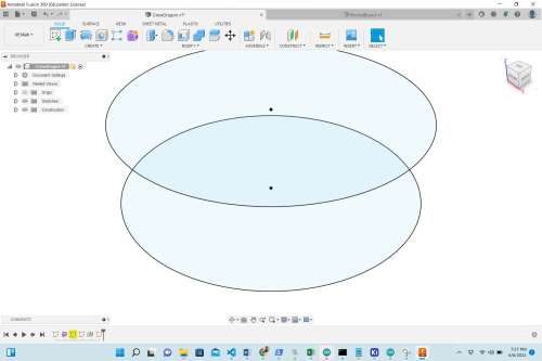
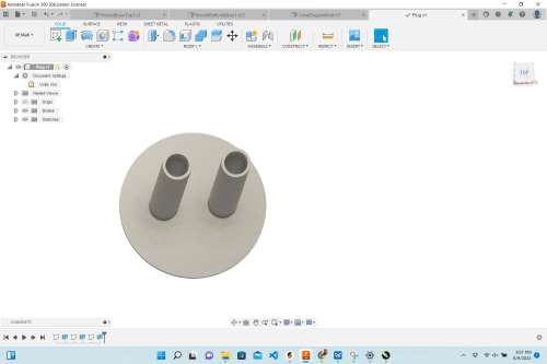
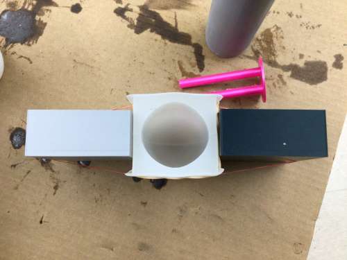
It was always my intention to make the rocket in this project an accurately scaled replica of an actual Falcon 9 rocket. Dr. Adam Harris suggested that I design the rocket to fit over top of the threaded steel rod to hide it when it is not being launched. I had some cardboard tubes at home, and I wondered if they might fit over the carriage assembly unit attached to the vertical rail and threaded steel rod. The following images explain how I measured and determined what the diameter of the rocke would be. I also looked up a lot of images of a Falcon 9 rocket on the Internet as shown in the table.
| Image | What Was Learned/Decided from this Image |
|---|---|
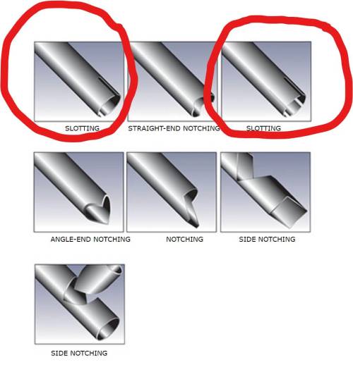 |
These are the types of joints that can exist between objects that are pipe-shaped. I initially was going to use slots as shown and circled here, but in the end, I felt it would be easier to use circular slots– one end is “male-like”, and the other end is “female-like”. |
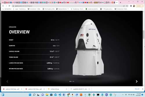 |
This provided the rough proportions for the crew dragon vs the overall height of the whole rocket with crew dragon. It also showed me that the crew dragon has fins at its base. |
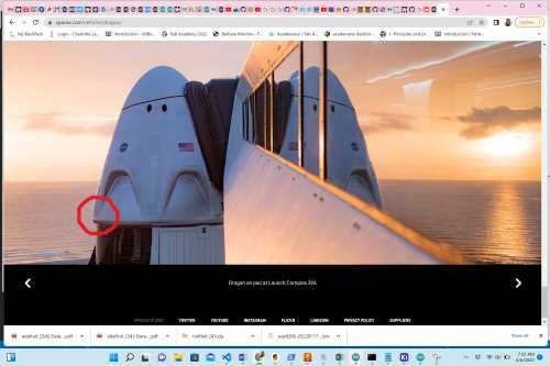 |
From this image, I could see that the crew dragon would have to overhang the overall rocket body. |
 |
This image showed me the logos that I would need to vinyl cut for my rocket. |
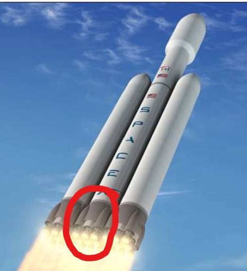 |
As I designed the rocket base, I needed to know the relative size of the 9 Merlin engines and how they are arranged around the Falcon 9 rocket’s base. |
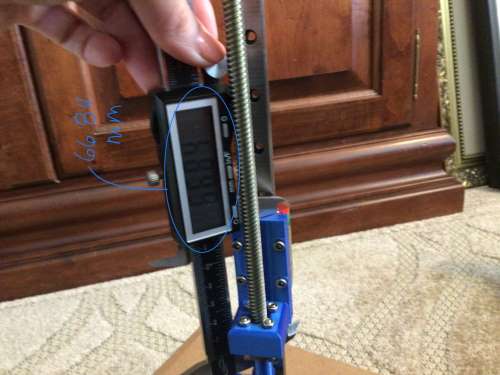 |
The height of the carriage/actuator assmbly on the vertical rail and threaded steel rod measured 66.84 mm. |
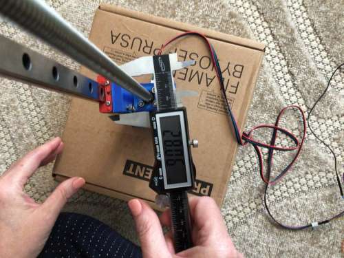 |
The width of the carriage/actuator assmbly on the vertical rail and threaded steel rod measured 28.06 mm. |
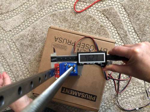 |
The depth of the carriage/actuator assmbly on the vertical rail and threaded steel rod from the front to the back measured 46.21 mm. This measurement meant that the body tube of the rocket needed to be greater than this in diameter. |
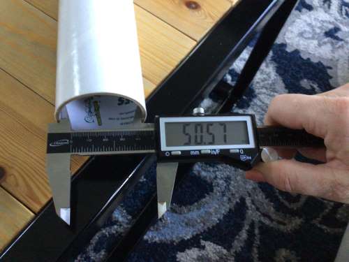 |
The isternal diameter of the cardboard tube I had on-hand had a diameter of the 50.57 mm. This value works for the rocket body width as it is greater than 46.21 mm (above). |
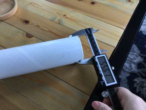 |
The outer diameter of the cardboard tube I had on-hand was 55.61 mm. When I did the math, the thickness of the carboard was roughly 2.5 mm. I decided to make my rocket body outer shell thickness to be 2 mm for easier dimensioning. |
Rocket Body Design
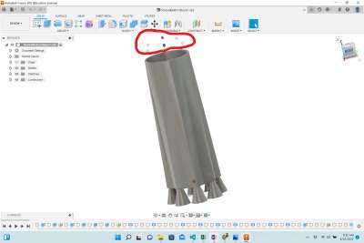
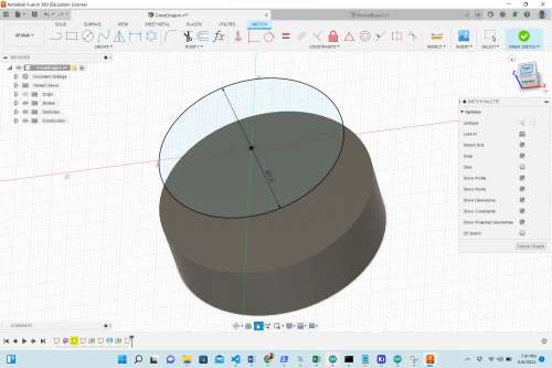
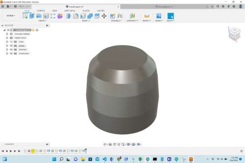
Now that I knew the rough dimensions to nmake the rocket’s body, I decided to design it in three parts: the base (where the engines are located), the middle section, and the upper section. The following images show the process of designing each section.
On a side note: It is important to mention that before I 3D printed any of these parts, I created a rocket body test file that would show me if my junction points between each section were accurate when fitted together. This file was created after I had creared each of the three sections. The image of this test file/print is shown under the “Top Portion of the Rocket’s Body” section below.
Lowest Portion of the Rocket’s Body
This table shows the designing of the lower portion of the rocket– the base. This was the most challenging part for me to design because this is the part that interacts with the carriage/actuator. When it was “done” (it still could use more modifications) I needed to tweak it two more times after I had 3D printed it. Each time I 3-D printed it, it was a 9+ hour job.
| Image | What Was Done Here |
|---|---|
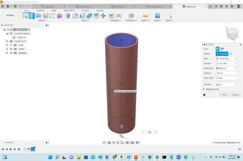
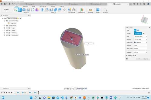
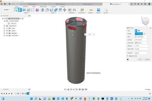
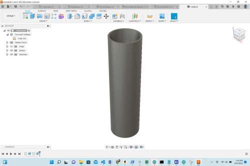
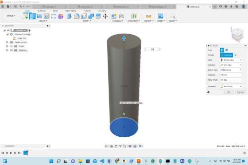 |
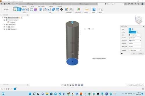
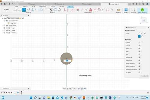
I began by making a circle that was 55.6 mm in diameter, and I extruded it 190 mm. |
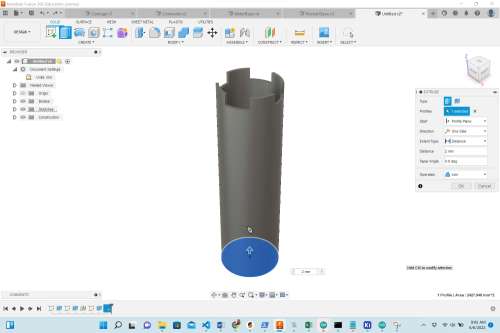
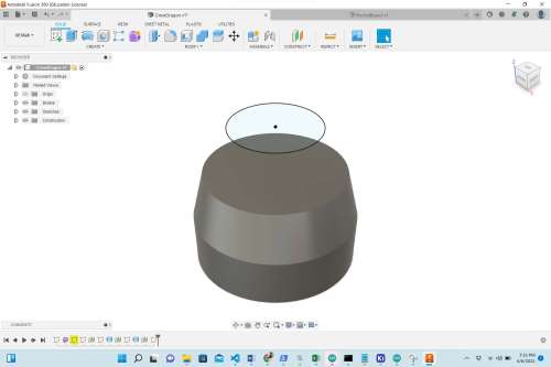
 |
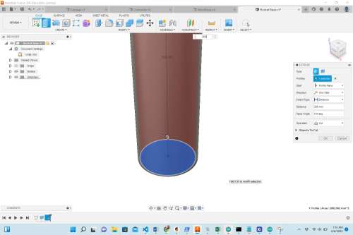
I created another circle, with a diameter of 50.5 mm, and I extruded it -190 mm in order to hollow it out. |
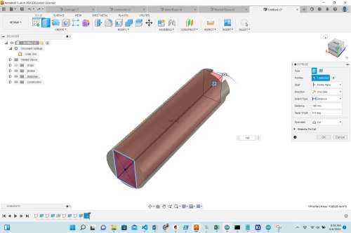
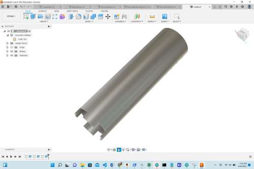
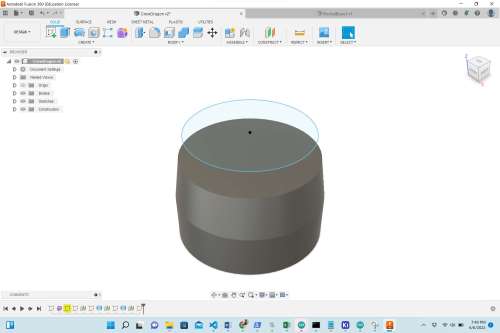
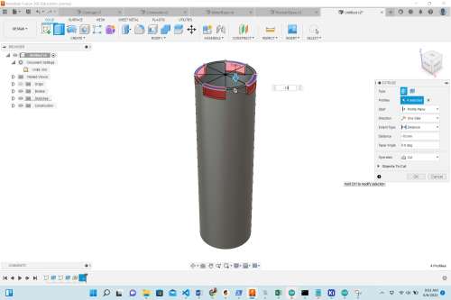 |
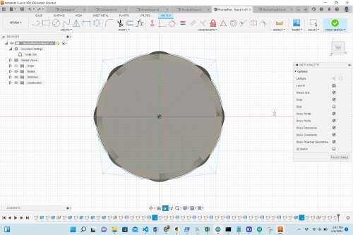
Using an offset plane created on the top, I used architecture lines to divide the circle into 8 equally-sized wedges. I then converted the architecture lines into actual lines, and I made slots out of every other wedge by extruding the small arc-shaped portions -10 mm. I would abandon this design later, and I made new (“male” and “female”)”slot-fit” junctions for all of the rocket bodies. |
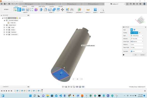
 |
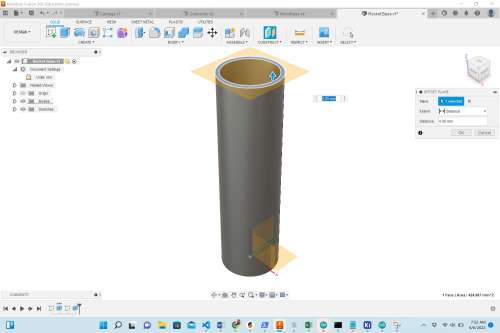
Here I selected the bottom circular plane and extruded it 2 mm in order to create a “floor” that would interact with the carriage/actuator assembly unit. |
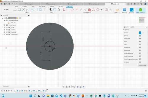
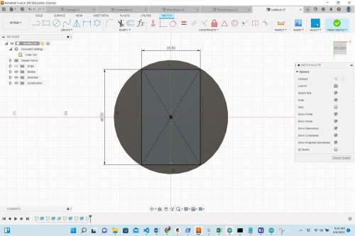 |
I knew that the carriage/actuator would have to fit through the “floor” I had just created, I made a rectangle that was 28.5 mm x 46.5 mm. At this point, it was my intention to just slide this around the carriage/actuator. I was thinking that if I twisted it slightly, that would provided enough contact for me to super glue the bottom of the carriage/actuator unit to the inside of this bottom “floor”. (Side note: this was very problematic later in that I incorrectly modified this part of the design twice. More on that later). |
 |
I extruded the 28.5 mm x 46.5 mm rectangle -3 mm so that only a rectangular hole was created in the “floor”. |
 |
I extended this rectangular “cut” through the entire length of the rocket’s body so that it would entirely fit over the carriage/actuator unit. |
 |
I extruded the 28.5 mm x 46.5 mm rectangle by -2 mm leaving just a rectangular hole in the bottom of the “floor”. |
 |
I wound up adding the bottom “floor” back into the design– removing the previously made rectangular hole because I wanted to be able to cut through the engines that were getting ready to be made. I knew that I needed to design 9 Merlin engines on the bottom of the base, so I placed a center circle in the middle with a diameter of 12 mm. Using architecture lines, I was able to determine where to place the circle for the other two rockets in line with the center one. I also used architecture lines to divide the bottom again into eight sections. But this time, I would place a circle on the lines, not in the wedge area. |
 |
This shows the placement where all nine of the Merlin engines would go. |
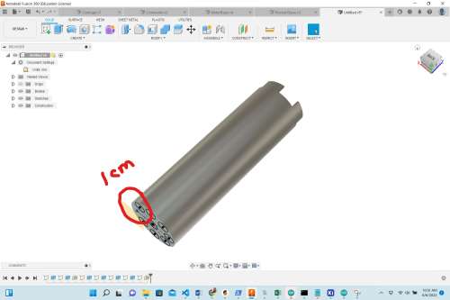 |
I created an offset plane 10 mm (or 1 cm) away from the previously-made circles. |
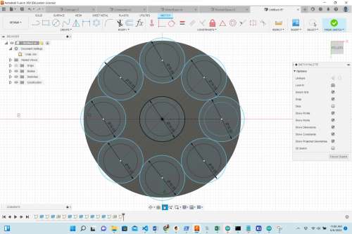 |
Over each 12 cm circle, I placed another center circle on the newly created offset plane that was 16 mm in diameter. I intended to loft all of the small circles with the larger circles, but Fusion 360 would not allow me to loft them all at the same time. |
 |
I had to remake all of the circles again, and loft them one at a time (the smaller circle to the larger circle). This was furstrating and a waste of my time, but I would not make that same mistake twice. |
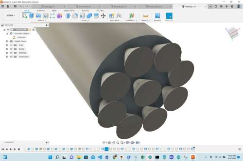 |
This shows all 9 of the Merlin engines placed on the rocket’s bottom. (The size of these would ultimately be modified– made much larger in the final design). |
 |
I now extruded the 28.5 mm x 46.5 mm rectangle -15 mm so that it cut this rectanglular shape out of the Merlin engines as well. The center engine was completely removed by this action. |
 |
While examining the shape of the Falcon 9 rocket at the bottom, I knew I needed to add fins as best I could. So I created lines to generate a “diamond-like shape”. |
 |
Using the lofting tool, I lofted the outer edge of the diamond shape to the external outer circle of the top. I was very pleased with this because it flowed smoothly into a new shape from bottom to top. |
 |
I created an offset diamond shape (offset from the first diamond shape added to the bottom), and also extruded it to the outer circle at the top. Again, I was pleased with how the bottom looked like actual fins. |
 |
This shows the first 3D print of the rocket’s base. Just before printing this part, I made a modification that– at the time made sense, but does not make sense now. Rather than having a rectangular-shaped hole in the bottom, I decided to make a circular hole that had a diameter of 20 mm. At the time, I was thinking that this part of the rocket could be slipped under the carriage/actuator unit and super glued to from the bottom. Nine hours later, when I started trying to assemble it, I was horrified with my stupidity. Nothing fit. |
 |
This image show the difference in the Merin engines as I had to redesign them. The attachment point to the bottom of the rocket was too flimsy, so I made the engines larger (which was more accurate anyway). |
 |
In my attempts to generate the best contact shape between the bottom of the rocket and the carriage/actuator unit, I finally wound up with– and using– base #3 in the image. This had a square portion at the end of the rectangle that allowed it to slide up the vertical rail. I would still need reinforcements for this though. I also doubled the size of the Merlin engines to provide more stability; that also was more proportional to the actual ones on a Falcon 9 rocket. |
Middle Portion of the Rocket’s Body
The middle part of the rocket’s body was the easiest part to make. Since the
| Image | What Was Done Here |
|---|---|
 |
I began by making a center circle with a diameter of 55.6 mm– the same diameter of the external part of the lower portion of the rocket (where the octagonal fins loft into the exterior circle of its highest portion). |
 |
I extruded the first circle 200 mm to form a solid cylinder. I assumed I could easily change these lengths if needed later to properly scale the entire Falcon 9 rocket. |
 |
On top of the original 55.6 mm center circle, I created another center cirlce with a diameter of 50.5 mm. This is the same value as the inner diameter of the lower portion of the rocket’s base. |
 |
To hollow out this part of the rocket, I extruded it 200 mm, and selected the “Operation” from the window to “Cut”. |
 |
Here I created an offset plane on the top in order to start forming the junction slots on the top. This would also have to be done on the bottom. |
 |
This view shows what the cylinder looked like as if looking down into it. |
 |
Using construction lines, I divided the circles into 8 equal wedges. This would help me to form the “slots” that I had intended to use at the time. This changed after I 3D printed my test file. |
 |
I converted the construction lines into actual real lines forming the wedges. I would then select every other outer portion of the wedge for extrusion. |
 |
Here I extruded every other outer wedge -10 mm to form the slots for the junctions with the upper part of the rocket. |
 |
I repeated the -10 mm extrusion on the bottom in order to create the junction slots that would come into contact with the lower part of the rocket. |
Top Portion of the Rocket’s Body
| Image | What Was Done Here |
|---|---|
 |
I began this portion of the rocket by re-creating a hollowed-out cylinder with an internal diameter of 50.5 mm, and an expternal diameter of 55.6 mm. These are the same inner and outer dimensions of the lower and middle sections of the rocket’s body. |
 |
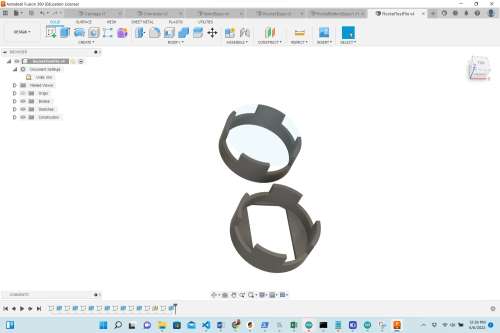
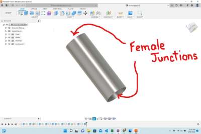
Using the same process of creating an offset plane on the top, dividing the circular area into 8 equal wedges, selecting alternating outer areas of the wedges and extruding them -10 mm, I created the slots for the junctions. It was at this point that I realized I was essentially making the same design as the middle portion of the rocket. I also realized that the slots I was creating would require glue in order to hold the two pieces together. I felt this would weaken the strength of the joint. So I decided to re-design the junction points so that one more-narrow end would simply fit into an equally opposite wider end. |
 |
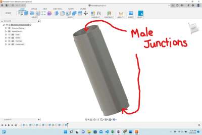
This shows a newly created “male” junction point. I decided I could simply make the middle section to have two “male” junctions, and the upper section have two “female” junctions. I could have simplified things for myself if I had made one end have a “male” junction and the other end have a “female” junction. |
I also modified the junction areas of the test file so that there was a “male” and “female” junction. The two pieces fit nicely together, and I found that I would not even need glue. The slots that were on the one side actually made the design much weaker, and I wound up removing those narrow slots in the end. The image below shows the changes in the junction test design.
 |
 |
|---|---|
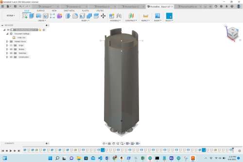
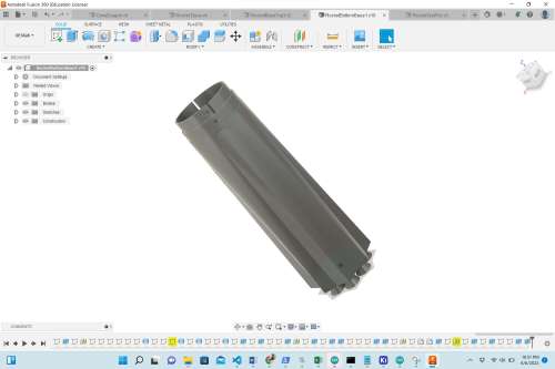
Final Rocket Body Designs
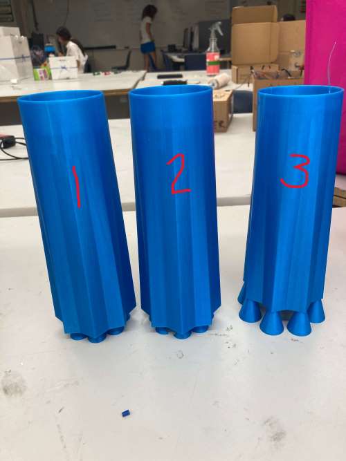
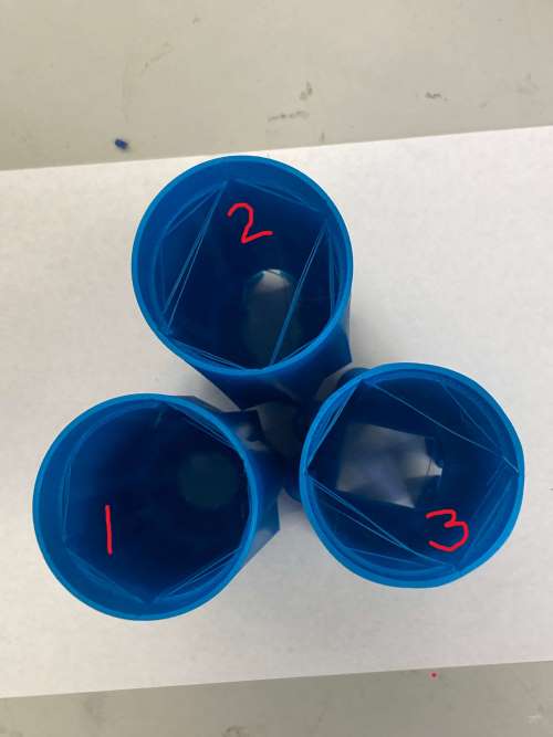
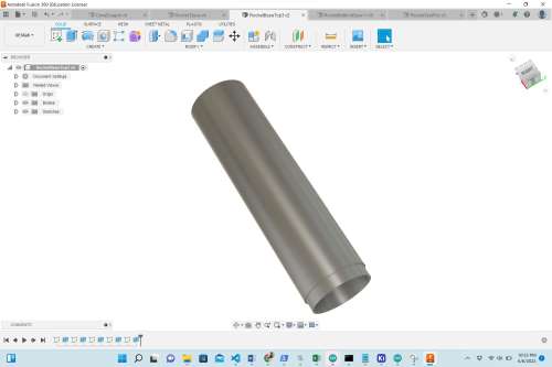
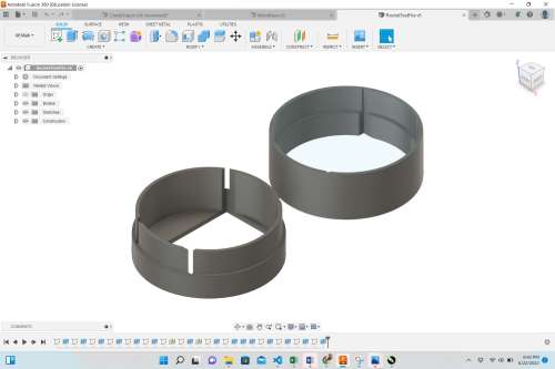
Now that I had determined the best junction for making the body of my rocket, I removed all of the slots from the ends of each portion and made the above-mentioned “male” and “female” junctions. The images below show each portion of the rocket.
| Rocket Bottom | Rocket Middle (with Female Junctions) | Rocket Upper (with Male Junctions) |
|---|---|---|
 |
 |
 |
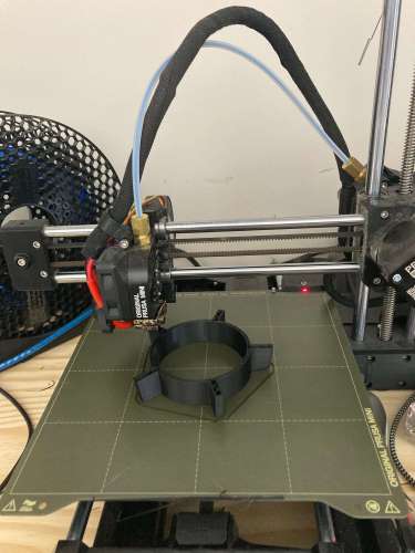
I was able to use six 3D printers at the same time in the Charlotte Latin School Fab Lab. This saved me an inordinate amount of time. The following video shows me 3D printing the rocket parts and carriage.
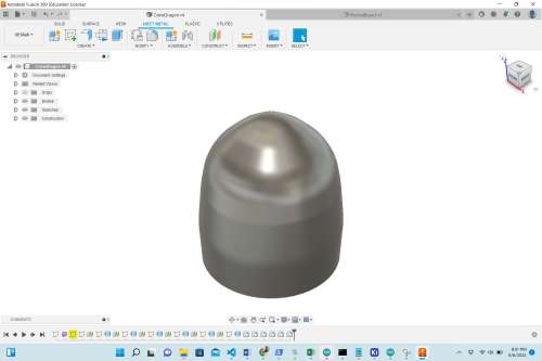
Crew Dragon Design
I always knew I was going to incorporate molding and casting into my final project, and after spending time looking at the exterior of the Falcon 9 rocket, I realized the best place to utilize this skill would be in making the Crew Dragon (or nose cone). I used Fusion 360 to design the crew dragon, and the table below shows the documentation of its creation.
| Image | What Was Done Here |
|---|---|
 |
I began by generation two parallel center circles (utilizing an offset plane that was 10 mm away from the first). The smaller circle had a diameter of 55.6 mm, and the larger circle had a diameter of 58 mm. I then used the loft tool to connect them, forming a solid. |
 |
Here, I created another offset plane with a center circle parallel to the others. Ths diameter of this circle was 51 mm, and I again utilized the loft tool to solidly connect them. |
 |
I continued to repeat this process with center circles. I didn’t care what the actual diameters were so long as the overall shape was right. |
 |
To make sure there was a significant enough “bulge” in the nose cone, I began to make the parallel center circles smaller and loft them each time. |
 |
This shows the lofting of each center circle and how the overall shape is starting to look like a roughl cone. |
 |
I continued in making the parallel circles smaller and smaller. |
 |
Once I was satisfied with the overall shape of the nose cone, I used the fillet tool to start smoothing the vertices where each loft occurred. |
 |
On the bottom of the cone shape, I created a center circle with a diameter of 55.6 mm. This diameter had to match the outer diameter of the rest of the rocket’s body. |
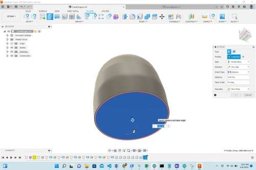
 |
In order to mill this shape in wax, I placed a box around it halfway through the vertical center of the entire nose cone. |
Once I had designed the upper shape of the crew dragon, I decided to design a section of black fins that are also on the actual crew dragon. These fins wound up serving as the perfect connector between the upper rocket body and the crew dragon. The following image shows the final crew dragon fin design.
 |
 |
|---|---|
To design these fins in Fusion 360, I made a ring (using the 55.6 mm outer diameter and the 50.5 mm inner diameter) and extruded it 2 inches. I then used construction lines to divide the ring into 5 equal wedges. I used the line tool to draw a rectangle with that line bing one of the sides that extended out from the ring 0.454”. I created an offset plane on the top if the ring and made parallel rectangles on the upper ring that extended out 0.704”. Using the loft tool (similar to how I had used it for the Merlin engines), I connected the two parallel rectangles on all five of the wedges (one at a time). When I 3D printed the fins, they were slightly too large, and would require a small amount of glue. I decided to re-print them, but this time, I shrank the size to 98%. This reduction wound up being perfect.
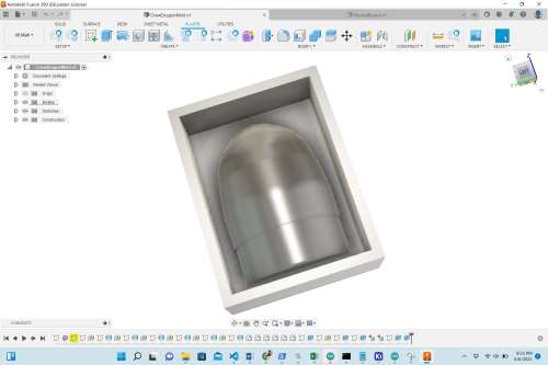
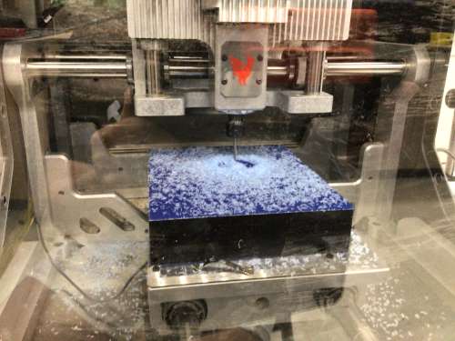
Molding and Casting Crew Dragon
At this point, I was ready to prepare my nose cone for milling in our larger, Bantam milling machine at the Charlotte Latin School Fab Lab.
| Image | What Was Done Here |
|---|---|
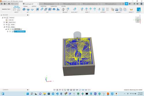 |
This image shows the start of the adaptive clearing (the rough) pass. |
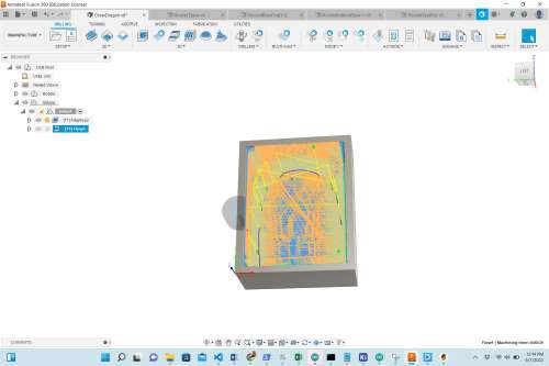 |
This is the second pass, the “Morph” 3D smoothing pass. For time’s sake, I wound up not carrying out this pass. The job without it was over 4.5 hours long. |
 |
I fused two large blocks of wax together (by using a heat gun to melt them), and I reiforced them with a perimeter of gorilla tape. This image was taken about 10 minutes into the 4.5+ hour job. |
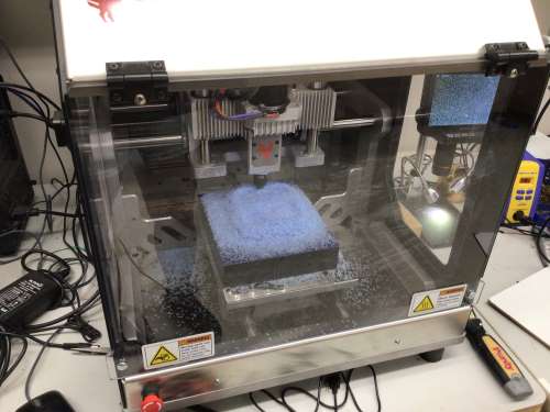 |
This shows the milling process after about an hour. |
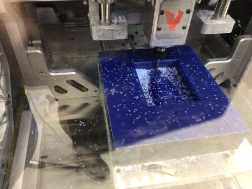 |
Roughly one hour into the job, I paused the milling machine and vaccuumed the pile of wax chips. |
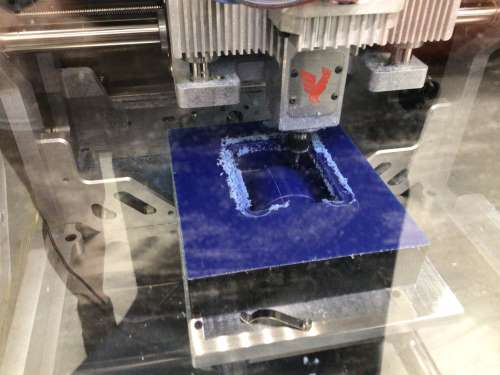 |
After about 3 hours, I paused the milling machine again so that I could vaccuum it again. However, I noticed that the collet was running into the sides of the wax. I decided to continue on with the job at this point though because it appeared as though the areas around the rectangular rim had already been cleared out. When I went to start the job up again, there was a glitch with the computer that would not let me simply press “play”. I had to restart the computer, and the milling machine all over again. Before doing this, I had to manually turn the threaded rod in the machine that was responsible for the Z axis because if the machine re-homed, it would likely run into the wax. (Colleague Zack Budzichowski suggested I do all of this.) Once I had raised the Z axis, I was able to start the job again, but it had to be started from the very beginning. So the part that was already milled out was “air cut” all over again. This was a time delay that was unfortunate. |
 |
Knowing that I was going to have to make a 2-part mold, I designed a “plug” for pouring the final material into the molds (to make a casting). I wound up not using/needing this in the end, but this would actually be utilized in the final day of my project work – INSIDE of the rocket’s base. |
This video shows the milling of the crew dragon mold.
Since I did not do the 3D “Morph” pass, I decided– when the job was done– to again use the heat gun to smooth the surface of the wax. This actually worked beautifully, and I was happy to have made that decision. As a backup, I also decided to 3D print the nose cone (on two different 3D printers in the Charlotte Latin School Fab Lab). When it came time to pour the silicone (for the soft mold), I decided that I would just go ahead and pour it into all three of the molds. I first heavily sprayed each mold with “Smooth-On Universal Mold Release”.
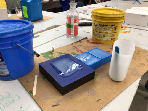
I wound up deciding to just use the two 3D-printed molds (since it would save a little time). The following images show my molding and casting setup.
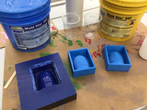 |
 |
|---|---|
 |
 |
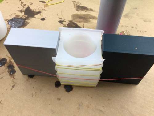
In order to create an optimal shape for the nose cone, I had to stregically use rubber bands. (Classmate Alaric Pan showed me how had used rubber bands with his molding and casting.) I also used two blocks on the end to provide pressure in the middle of the mold. For the silicone, I used Moldstar 20T, and for the hard cast, I used Smoothcast 300.
The following video shows me carrying out the molding and casting process.
The following image shows the molded crew dragon, and how I modified it for attaching the 3D-printed black fins. I used the band saw in the Charlotte Latin School Fab Lab to trim the (gray) rocket body “pipe” I had used when molding it.
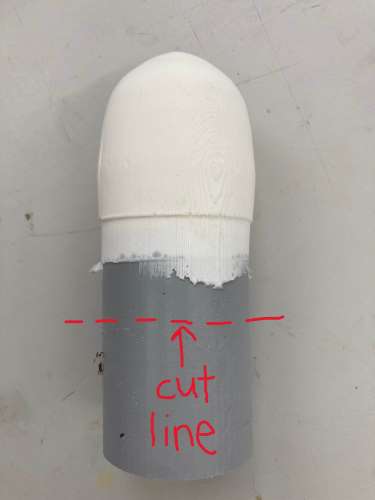
I then used the sanding machine to sand the molded material so that it fit snuggly into the crew dragon fins. Once this was done, I was able to attach it to the rocket’s body.
Decorating the Falcon 9
Once I had the rocket parts 3D printed and connected, I painted the whole thing white.
I did Internet searches to find and decide which logos I would put onto the side of the rocket (basically, the front of it). The following image shows the assembled rocket before adding the vinyl-cut logos.
| Image | What Was Done Here |
|---|---|
 |
This is a screenshot of the SpaceX logo I decided to use. I used two colors, royal blue and silver (for the slash in the “X”). |
 |
This was the most important logo (in my opinion), and I was happy with how it looked on the rocket. |
 |
This is a screenshot of the American flag I decided to use. I used two colors, blue for the stars and red for the stripes. Since the rocket is white, I did not have to use white. |
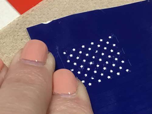 |
I had to use sharp tweezers to remove the tiny stars. |
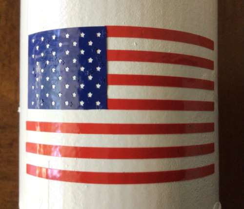 |
I was really impressed with how well the Cameo Vinyl cutter cut the stars– which were tiny! I feel someone must have just changed the blade on that particular vinyl cutter. |
 |
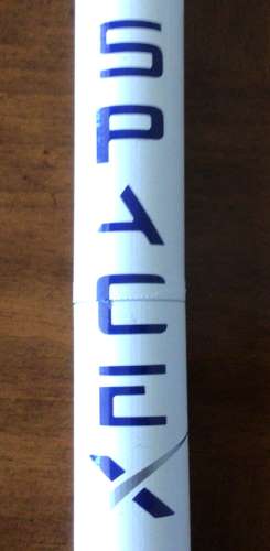
This is a screenshot of the Falcon 9 logo (that SpaceX has on the top of the rocket). I used two colors, red and black vinyl to make this logo. |
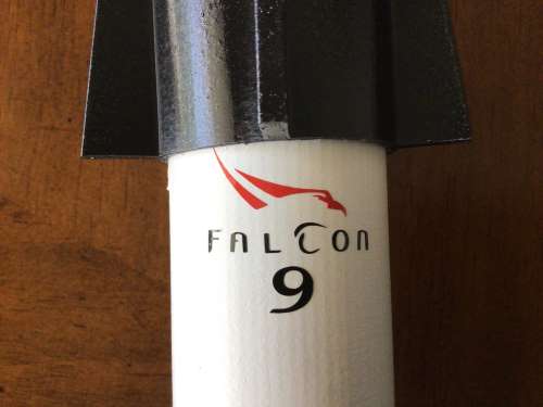 |
This was the most difficult logo to make. The black letters were very thin, and they did not adhere well to the transfer paper. I wound up having to tediously place the letters on individually. This is the logo I am most proud of. |
 |
This is a screenshot of the NASA logo I decided to use. |
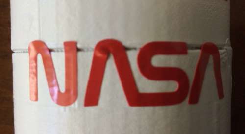 |
This was the easiest logo to make because it was only one color, and the letters had decent thickness for grasping with tweezers. The only problem was that the NASA logo wound up having to be placed on the seam of two of the rocket’s body tubes. |
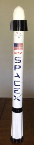
This is what the final rocket looked like after it had been assembled and all of the “decorating” had been done.
Electrical Housing
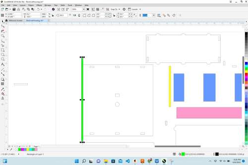
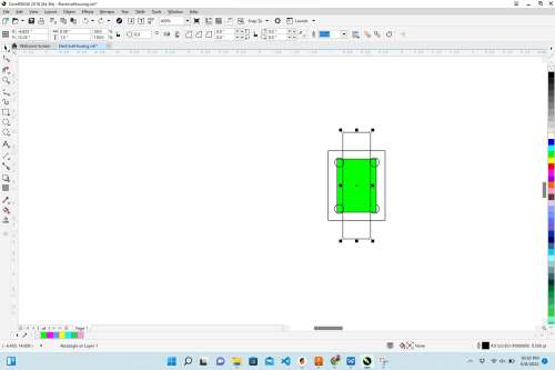
It was now time to design the electrical housing that would hold the Raspberry Pi, Satshakit, NEMA17 stepper motor, Doppler sensor, OLED and RGB LED. I wanted to design this part of the project so that it would not need glue and could be easily taken apart if needed and re-assembled. I wanted to use the blue acrylic/plexiglass that we already had in the Charlotte Latin School Fab Lab; was very close to the SpaceX blue color I had seen used.
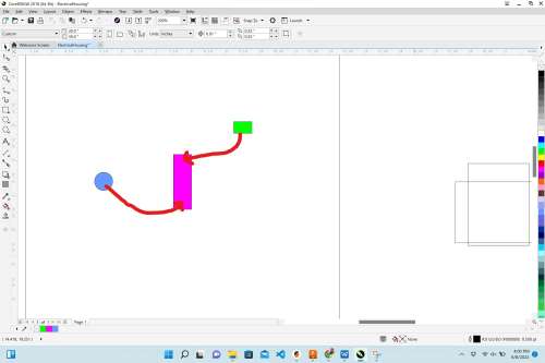
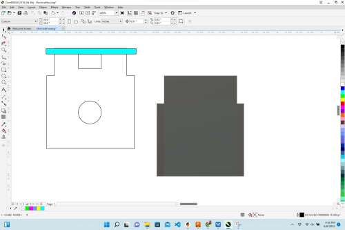
| Image | What Was Done Here |
|---|---|
 |
The first thing I needed to do was to make the holes for the square rail the carriage slides along and the threaded steel rod. |
 |
I made a rectangle 0.52” x 0.33”, and a circle with a diameter of 0.6” in diameter. These measurements are slightly larger than the dimensions of the rail and rod to allow for movement as the motor will cause vibrations. |
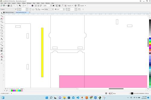
 |
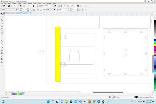
I went back into Fusion 360 and took a screenshot of the bottom “footprint” of the motor mount, making sure to get as close to the outer lines as possible. I then added this screenshot in Corel Draw and made it the same size (1.97” X 2.28”) as the actual motor mount. Using straight lines, I traced the outline of the motor mount around the previously made rectangle and circle. |
 |
To make slots on two of the four sides for each of the “half-biscuits”, I made 0.2” x 0.5” rectangles that were 0.175” from the edge. The acrylic/plexiglass I was using measured 0.2” with the callipers. |
 |
On the two other sides (out of the four), I created ellipses with diameters of 0.5” and 0.4”. This allowed me to place the ellipses symmetrically on the (what would be) vertical edges. I used the “virtual segment delete” tool to remove the internal/unwanted half of the ellipses. The half biscuits were strategically placed at the same distance from the horizontal top and bottom so that they aligned with the slots made on the other two (Out of four) sides. |
 |
To create the half biscuits on the horizontal edges of the electrical housing, I made three identical (blue) rectangles to ensure that the outer two half biscuits were equally spaced from the edge, and that the middle half biscuit was in the direct center of the horizontal top and bottom. Also seen in this image, the top and bottom of the electrical housing were made to be 9.4” x 9.4”. |
 |
I used the same blue rectangles to measure where to place the correspnding slots for the half biscuits that were just made. |
 |
Now that the slots were accurately placed on the top and bottom, I used a long rectangle (0.2 mm x 10.5”) as a guide to make sure I placed the new slots the same distance from the edge. |
 |
Here, I rotated the sides that would be adjoining to make sure that the half biscuits aligned with their corresponding slots. |
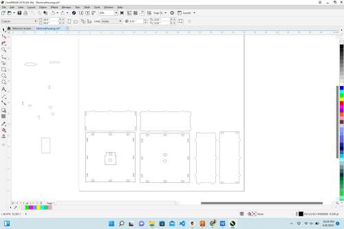 |
This is what the six sides looked like as they were completed. |
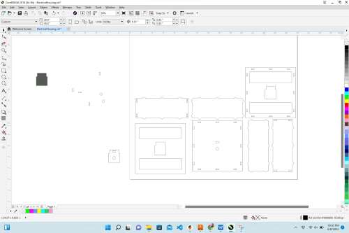 |
I decided to add an additional layer to the bottom of the housing unit to add more weight and try to prevent the potentially top-heavy rocket from tipping it over. I to both of the bottom pieces, I added two equally-sized rectangles that I could hinge to allow me to access the elctronics if repairs were needed. |
 |
Each hinge has four holes on the corners for small screws. I used callipers and measured the distances bewtween each screw hole as well as its distance from the edge. I used rectangles with those dimensions to place the screw holes appropriately. |
 |
I used a 1” x 10” (yellow) rectangle to make sure I placed the hinge areas equidistant from the sides. It did not really matter where these were placed, and I didn’t have to align these holes with another interacting piece (aside from the hinges). |
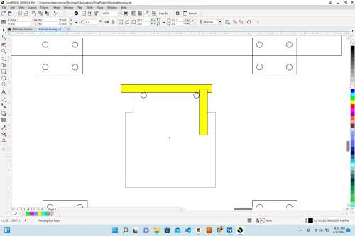 |
In this image, I am using (yellow) rectangles that are the same thickness as the distance of the screw holes I made in the motor mount design. |
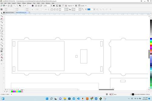 |
To complete the design, I added rectangles for the touch screen, RGB LED, Doppler sensor, and OLED. This image does not show the OLED rectangle. I had inadvertently left it off, but added a 0.75” x 1.0” rectangle before cutting it on acrylic/plexiglass. |
Once I had made all of the lines in the Electrical Housing Unit “hairline” for cutting on the laser cutter, I did numerous test cuts out of cardboard.
The following images show errors (on the upper right) in side measurements and (on the lower left) the motor fitting perfectly in the center. The following video shows a time lapse of me trying to fit the cardboard test pieces together, and the images show the troubles I faced.
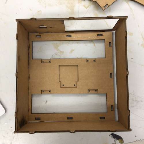 |
|
|---|---|
 |
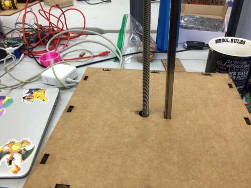 |
Once I had resolved alignment issues, I laser-cut the design on the blue acrylic/plexiglass.
The following video shows me putting the hinges on the bottom piece of the electrical housing, attaching the two bottom pieces together, and screwing the motor into the bottom piece.
All of the sides of the electronics housing fit nicely into their appropriate slots, and no glue was used. However, it took about 8 hours to troubleshoot and modify the design and measurements so that they would fit appropriately.
These images show me successively adding electrical components to the housing.
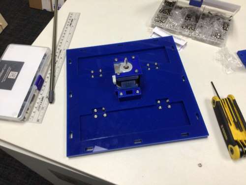 |
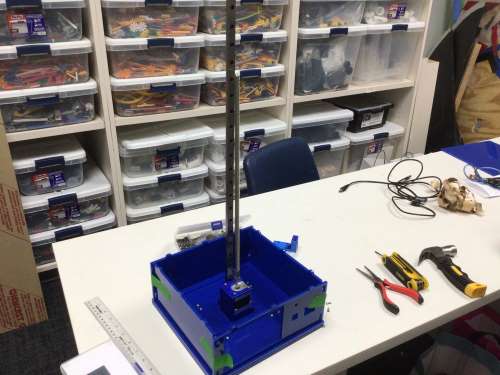 |
|---|---|
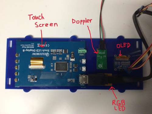 |
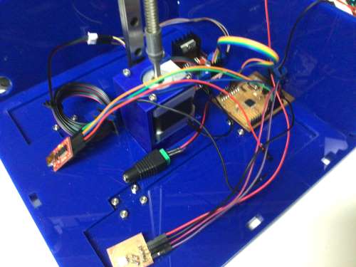 |
Once I had the electrical devices placed where I wanted them, I used Nitto tape to adhere the Raspberry Pi, Satshakit and stepper motor driver to the bottom of the blue electrical housing unit making sure to stay clear of the hinges doors. I also started to clean up the wiring using zip ties. The following image shows me doing this.
In the next iteration, I plan to glue small acrylic square wire guides to the interior sides of the electrical housing unit. I had actually designed them and laser cut them, but I ran out of time to actually adhere them.
Putting It All Together
When I 3D printed the carriage, I found I had to modify the holes on the vertical part to get them to properly align with the holes in the actual carriage that slides along the metal rail. The image below shows the iterations that were needed to reach a perfect fit.
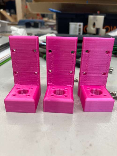
The following three images show how I placed the NEMA17 stepper motor onto the motor mount, and connected the threaded steel rod and metal rail together using the connector. I also screwed the carriage into the carriage that was on the rectangular metal rail.
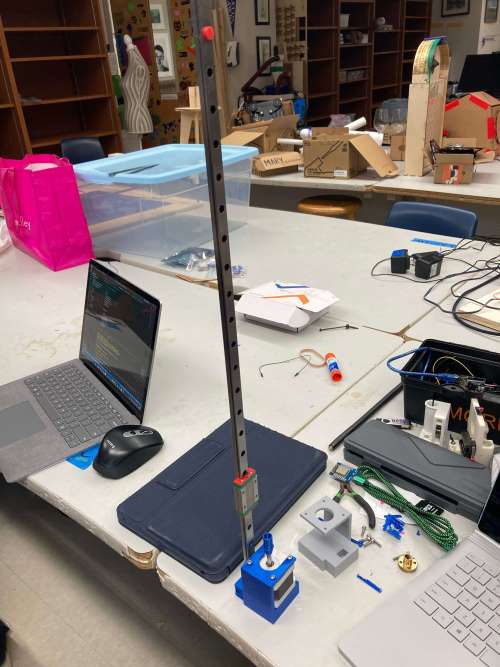 |
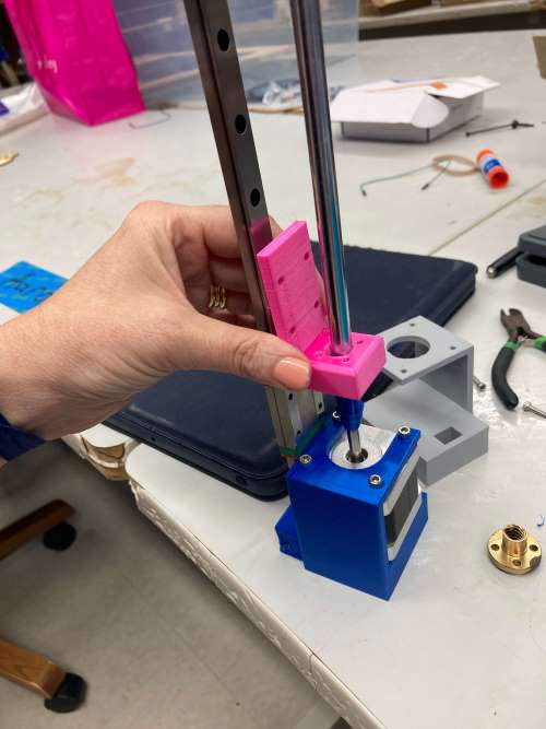 |
|---|---|
The following video shows me testing the actuator and carriage being lifted by the spinning of the threaded rod (either by hand or with the motor).
Once I had the mechanics worked out, I combined the codes for the stepper motor, the Doppler sensor, and the RGB LED into one code (below).
// #include <FastGPIO.h>
// #define APA102_USE_FAST_GPIO

#include <APA102.h>

// Define which pins to use.
const uint8_t dataPin = 3;
const uint8_t clockPin = 2;

// Create an object for writing to the LED strip.
APA102<dataPin, clockPin> ledStrip;

// Set the number of LEDs to control.
const uint16_t ledCount = 1;

// Create a buffer for holding the colors (3 bytes per color).
rgb_color colors[ledCount];


// Set the brightness to use (the maximum is 31).
const uint8_t brightness = 2;

#define Sensor 12

// Include the Arduino Stepper Library
#include <Stepper.h>

// Number of steps per output rotation
const int stepsPerRevolution = 200;

// Create Instance of Stepper library
Stepper myStepper(stepsPerRevolution, 5,6,7,8);

void setup()
{
  pinMode(Sensor, INPUT);
  myStepper.setSpeed(150);
  myStepper.step(1);
  myStepper.step(-1);
  Serial.begin(9600);
}

/* Converts a color from HSV to RGB.
 * h is hue, as a number between 0 and 360.
 * s is the saturation, as a number between 0 and 255.
 * v is the value, as a number between 0 and 255. */
rgb_color hsvToRgb(uint16_t h, uint8_t s, uint8_t v)
{
    uint8_t f = (h % 60) * 255 / 60;
    uint8_t p = (255 - s) * (uint16_t)v / 255;
    uint8_t q = (255 - f * (uint16_t)s / 255) * (uint16_t)v / 255;
    uint8_t t = (255 - (255 - f) * (uint16_t)s / 255) * (uint16_t)v / 255;
    uint8_t r = 0, g = 0, b = 0;
    switch((h / 60) % 6){
        case 0: r = v; g = t; b = p; break;
        case 1: r = q; g = v; b = p; break;
        case 2: r = p; g = v; b = t; break;
        case 3: r = p; g = q; b = v; break;
        case 4: r = t; g = p; b = v; break;
        case 5: r = v; g = p; b = q; break;
    }
    return rgb_color(r, g, b);
}

  // set the speed at 60 rpm:


void loop()
//bool Detection= digitalRead(Sensor);
{
  int sin;
  if(digitalRead(Sensor) == HIGH)
  {
    colors[0] = rgb_color(255, 255, 255);
  }
  else
  {
    uint8_t time = millis() >> 4;
    uint8_t p = time - 0 * 8;
    colors[0] = hsvToRgb(p, 255, 255);
    //colors[0] = rgb_color(p, 100, 100);

    //delay(10);
  }

  ledStrip.write(colors, ledCount, brightness);

  if (Serial.available() >0) {
    while (Serial.available() >0) {
      sin=Serial.read();
      // Serial.println(sin);
    }
    // step one revolution in one direction:
    myStepper.step(-6000);
    delay(10000);

    // step one revolution in the other direction:
    myStepper.step(6000);
  }
}
The above code is my final code. It took the help of Jeremy Proffitt to get the Raspberry Pi communication working with the Satshakit via SPI by adding this part of the code:
  if (Serial.available() >0) {
    while (Serial.available() >0) {
      sin=Serial.read();
      // Serial.println(sin);
Jeremy Proffitt also helped me to add a line of code to make the RGB LED pause on white light when motion is detected by adding the following line of code:
colors[0] = hsvToRgb(p, 255, 255);
The following video shows the first test with all three of the devices together.
And this video (below) shows me testing the stepper motor using 8400 steps, which took the carriage/actuator to the tip of the threaded rod without causing it to come off. This value would actually be lowered to 6000 because the weight of the entire rocket eventually caused it to nearly come off.
The time had come to determine how the carriage/actuator was going to loft the rocket. I had thought that I would glue the inside bottom of the rocket base (just on the other side of the Merlin engines) to the carriage/actuator. However, after a discussion of colleage (and mechanical engineer), Zack Budzichowski, I decided to use the “plug” I had 3D designed and printed to help with this interaction. Using the band saw in the Charlotte Latin School Fab Lab, I cut off the two hollow tubes protruding from the circular base, leaving just the circle and two holes. I then traced the square shape of the bottom of the carriage onto the circle and once again used the band saw to cut on the lines. This allowed the carriage to fit through the plastic circle with ease. I then used a hot soldering iron to melt and widen the one remaining hole so that the threade steel rod could fit through it. I super glued the modified plug into lace inside the rocket’s base (as shown on the left below). Zack Budzichowski suggested that I loft this same shape (as shown on the right below) and glue it all into place.
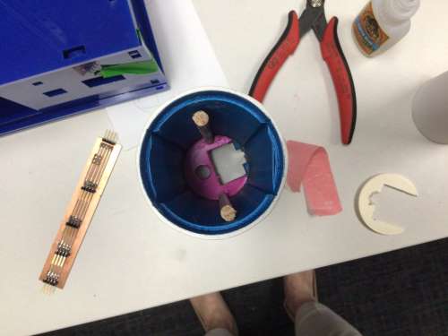 |
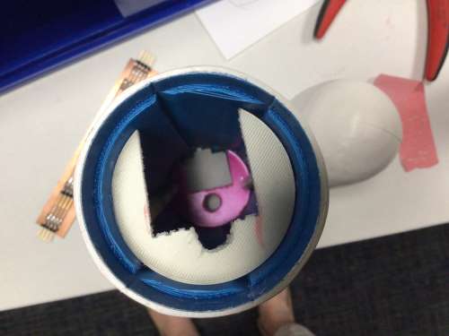 |
|---|---|
I started to 3D print another “plug”, but this time, I stopped the job when it got to the printing of the hollow tubes (so as not to waste PLA by just cutting it off later). To loft the second modified “plug”, I cut two equal 1/4” wooden dowels that were in the Fab Lab. The following image shows the two lofted plugs that would now serve as the rocket’s guide as it moved up the threaded steel rod/metal linear rail during “liftoff”. This was the most “messy-looking” part of my project, but it was a crucial feature that wound up helping significantly. In the future, I will add these shapes to the inside of base part of the rocket so that they can be 3D printed into it– making it more “clean” and appealing to the eye.
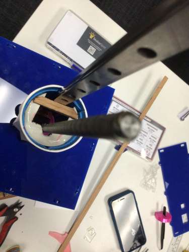
As I was testing the electronics, I was finding the interaction between the Doppler sensor and the RGB LED to be very temperamental. Many times, the RGB LED would simply go very bright, and it would also freeze, but at other times, it would function properly. It took the help of Mr. Christhoff Khouri to determine that there was a bad trace on pin 3 of the Satshakit. (I had been thinking there was an issue with the code). Mr. Khouri showed me how to troubleshoot the code by only changing one factor at a time. From this testing, Mr. Khouri and colleague, Adam Durrett, (also helping to troubleshoot) determined that part of the code for the RGB LED was looping incorrectly, and they helped to resolve this the night before the presentations. To remedy the loose trace, more solder would have to be added, or I re-mill and stuff another Satshakit. For time’s sake, I “wriggled” the Satshakit until the trace was in the proper position, and quickly and carefully ran the tests for my video.
Christhoff Khouri also showed me how to get the touch screen working. He was familiar with using OBX video streaming with Raspberry Pi’s, and we worked to add SpaceX’s live streaming of rocket launches added to the Raspberry Pi (python code). However, we soon realized that OBX is no longer supported by the most current version of the Raspberry Pi OS. Now, VLC is recommended. Due to the time constraints (this was all occurring the night before my presentation), we decided to simply just add a still image of a rocket launch to the touch screen. Since the touch screen acts just like a monitor, this was the best alternative. I hope to add the live streaming to the device with more time for refinement.
The following video shows me running the device all the way through with the fake launch sequence set as “true” (instead of “false”) in the Raspberry Pi (python) code.
I had forgotten to plug in the 5V external power supply for the NEMA17 stepper motor! I was so tired at this point, I was beginning to make simple mistakes. It was actually commical how many times I would run the test and forget this step! The following video shows the device working from start to finish.
I was so proud of the way the SpaceX Launch Alert was functioning, I couldn’t bring myself to turn it off. However I had managed to “wriggle” the loose trace into its proper place, the whole device was functioning beautifully. As I left it plugged in on my office desk, and from the room across the hall (many meters away), I could see the RGB LED fading in and out of the colors of the rainbow. When I would walk into the doorway, I could also see the RGB LED change to solid white. That part (as simple as it was) was very heart-warming to me– thinking of my grandsons playing with this feature.
The following images show the internal wiring. In an attempt to control the wires withing the electrical housing, I laser-cut squares that were three different sizes for the wired to pass through and be held to the sides of the acrylic housing. I also used zip ties to control the extra-long cable going from the motor driver and the NEMA17 stepper motor.
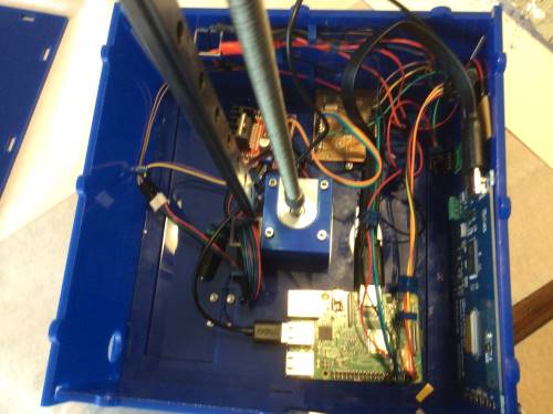 |
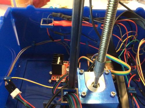 |
|---|---|
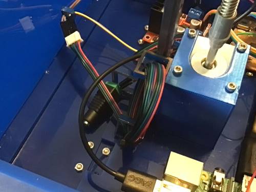 |
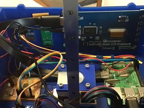 |
The following image shows the final project (not plugged in). No glue is needed to hold the outer acrylic sides together.
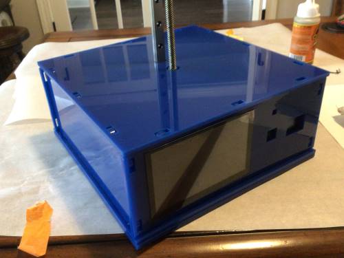
| Links to Files |
|---|
| CDR’s |
| STL’s |
| *.f3d’s |
| GRBR’s |
| Codes |