5b. Electronics Production- In-House PCB Process (CLS Adults)
This week, our group was asked to learn the process of milling PCB’s and– as extra credit– send our PCB out to a professional board house.
Group Work
characterize the design rules for your in-house PCB production process extra credit: send a PCB out to a board house
To begin our group project work for this week, we started with prepping the file provided to us. You can find a link to all files used for this assignment below.
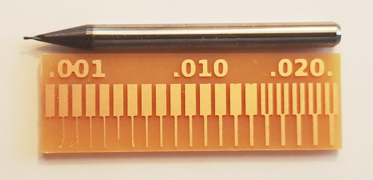
This linetest file will allow us to test how well our 1/64” end mill bit will mill a board. The first step was to convert the jpeg to an svg file. To do so, we opened the file in CorelDraw and did a bitmap trace. As part of the trace, we did the advanced method of removing everything that showed up as white in the file. This allowed us to only use the part of the image that left the traces we needed.

Once we cleaned the image as needed, we exported the file as an svg and proceeded to the milling process.
Our lab uses the original Bantam Tools (Othermill) Desktop PCB Milling Machines. We prepped the material (FR-1 single sided boards) with Nitto tape and adhered it to the lower left corner of the spoilboard. Next, we loaded the svg file created in the above step.
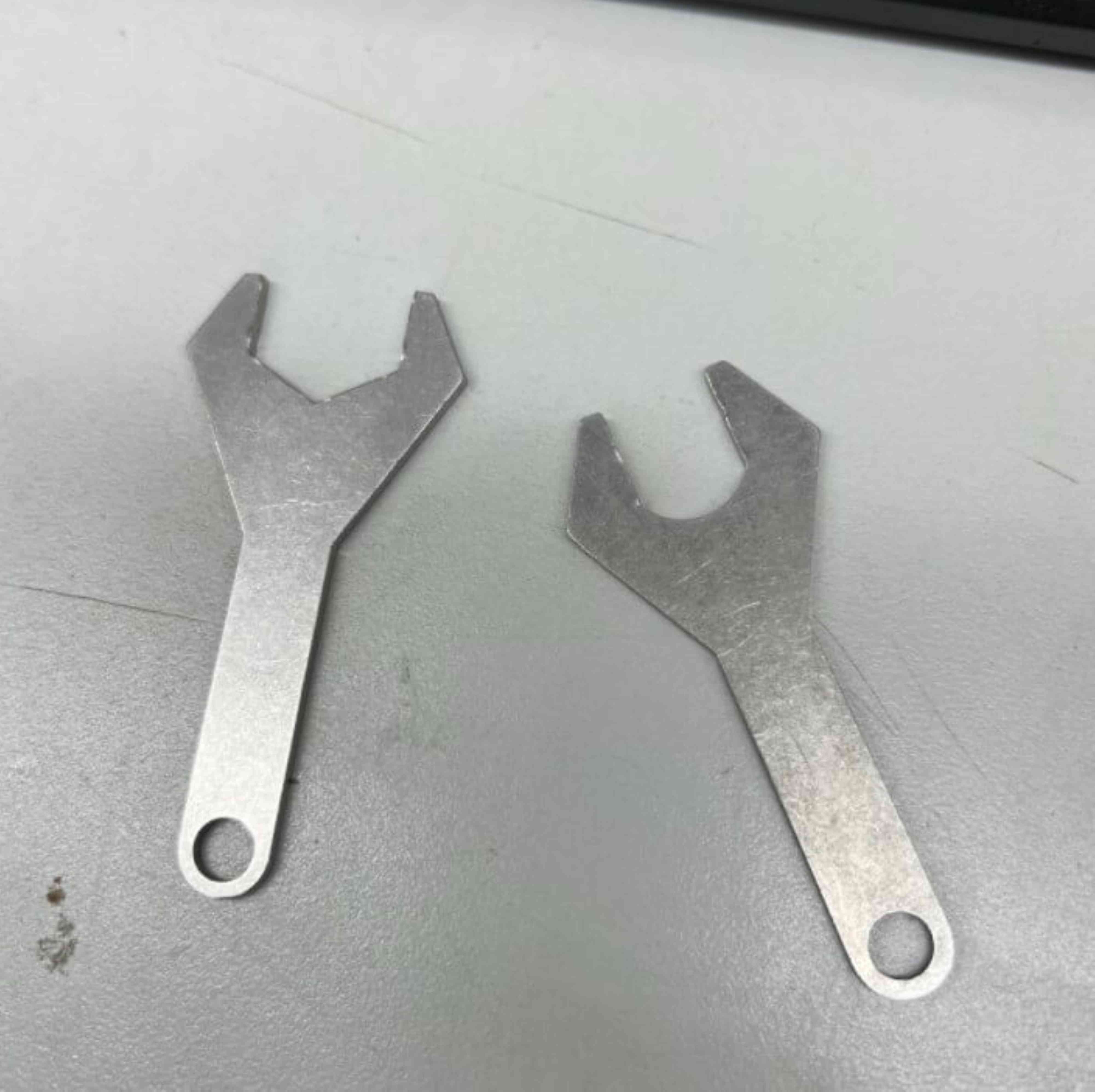
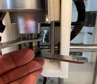
Once the file was loaded, we needed to change out the bit. We selected the change tool button and the machine moved the spindle for easier access. Using the two included wrenches, we loosened the collet and inserted the 1/64” bit, making sure the shaft was as flush as possible with the base of the collet. Because the level of insertion, as this point it is very important to find out where the bit is on the z-axis. So, after we change the bit out, we press the button for “locate tool”. This step allows the machine to “locate” the bits location in space (on the z-axis).
Once we had the bit set, we needed to verify the height of the material. One of the really helpful settings on the Bantam machines is something called “Bit Breaker”. This built-in function allows you to calculate the thickness of your material. It is a PCB probing system that uses a conductive clip electrically connecting your PCB with the bed. Read more details here.
After confirming and accepting the material thickness, the last few steps included opening the file and making final adjustments. We clicked open file and moved the X and Y placement to (4,0) to make sure there was enough clearance between the FR-1 board and the metal bracket. We confirmed in the software that the correct bit (1/64”) is selected, made sure “traces” and “cutout” are both selected, and the engraving depth looked good. Another good check is to confirm the time to actually mill the board. We noticed it would take just under 6 minutes which sounded correct so we set it to mill.
Once our board was done, we were shocked to find the bit had removed almost everything from the board!
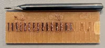
Something was not right. We checked our settings, rerunning the above steps. What ended up happening was that someone had accidentally put a 1/32” bit into the 1/64” bit container! The software settings were correct, but the bit was not. We quickly discovered we actually did not have the correct bit to use. As we waited for the order to arrive, we decided to test to see if we actually selected 1/32” for the bit in the software, how it would affect the milling. We added the 1/32” bit back into the collet, and this time selected 1/32” for our bit in the software. Here are the results of that run:
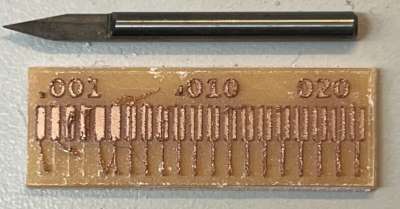
While we were working, we also wanted to see how an engraving bit would change the finished product. We knew it would be able to mill the smaller sections, but at what cost? We decided to test this with a .005” engraving bit. Instantly we could see using a bit like this would get us better results, but would take 3+ times longer - just over 22 minutes! We went ahead and ran the test because our correct bit had still not arrived.
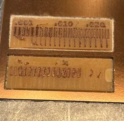
One of our colleagues was cleaning out the bins and discovered a 1/64” bit for us as we were finishing up this last process. We knew the bit had been used, but wanted to try to mill a correct board anyway. Following the same procedures as above, and changing the bit back to 1/64” we set everything up another time!
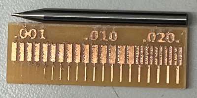
The results came out as we expected. The edges are a bit rougher than we would have liked, but we think that is because we were not using a brand new bit. After brushing off the burrs and washing the board with soap and water, we are happy with the results! The image above should be compared to this image.
Tool: 1/64” flat end mill Feed rate: 5.669 in/min (144 mm/min) Plunge rate: 0.472 in/min (12 mm/min) Spindle speed: 12,000 RPM Max pass depth: 0.002” (0.05 mm)
Workflow
At the start of this week’s work, Tom Dubick shared a .gbr file with us for an ATMEGA328 PCB. We worked as a group to discover the process and learn the needed workflow for using desktop Other Mill milling machines. In doing this, we also needed to understand Bantam Tools software, which our milling machines use.
The following workflow is what we came up with.
Preparing Materials for Milling (on Other Mill)
- Download .gbr file for milling.
- Ensure the other mill is clean and free of debris. Using shop vacuum, suction debris from the metal bed. (Vacuum out any materials leftover from previous use).
- Wipe the bed with alcohol-saturated paper towel.
- Turn on Other Mill milling machine.
- Open Bantam Tools software on computer.
- Obtain new prototype board.
- Add (double-sided) Nitto tape to back of prototype milling board (enough to nearly cover entire surface).
- Use callipers to measure the length, width and thickness of the prototyping milling board with the tape.
- Remove plexiglass safety window(s). (Removing front and both side safety windows provides ample room for both hands inside machine.
- Remove paper backing from (double-sided) Nitto tape and affix prototyping board to the metal bed. Be sure to place the prototyping board snuggly in the front left corner.
- Press firmly on prototyping board so that the entire board comes into contact with the metal bed.
- Firmly press and slide the green plastic “scraper” over the entire surface of the prototyping board to ensure proper adhesion to metal bed.
- Obtain proper bits to be used. (We used a 5-degree [0.005] and 1/32 bits to mill our PCB’s). (Use flat end mills for cutting 2D shapes like circuit boards, flat-sided 3D shapes, and for detail work. Use ball end mills for cutting curves and 3D shapes into woods, waxes, and plastics. Use engraving bits for fine detail work.)
- Insert (and start job with the higher detail) bit into the milling machine.
- Make sure blue rubber covering is on the sharp end of the bit or that the square foam piece is resting under the bit before removing/changing it. (If the bit is dropped, these will prevent the bit from chipping).
- Use small wrenches (one in each hand) to turn the collets in opposing motions to remove/change bits.
- When tightening collets after swapping out the bit, give them one more moderately hard twist to finish.Do not tighten the collet too much, and NEVER fully tighten the collet when there is no bit in it.
- Place your wrenches on top of the milling machine. There are magnetic pockets on the top of the milling machine to keep the wrenches handy while you’re working.
- Put the safety windows back into place.
Configuring in Bantam Tools Desktop Milling Machine Software
The Bantam Tools Desktop Milling Machine Software controls the Othermill. Load PCB (or other) design files into the Bantam Tools software and the program will determine the optimal toolpaths to complete the milling project. Bantam Tools Desktop Milling Machine Software supports the following file types: Vectors (.svg), EAGLE (.brd), Gerbers, and G-code (.nc, .tap, .gcode).
- Open Bantam Software, click File > Open or the Open Files button on the right side of the the software window.
- Navigate to the directory that contains your Gerber files.
- Open the desired Gerber file.
- Select tool (end mill or engraving bit) by selecting “change”.
- Choose tool from “New Tool” dropdown choices. -Install tool by loosening collet and replacing tool. (This may have already been done when preparing the materials for milling).
- Click “continue”.
- Home the mill. Be sure that the installed tool/bit touches the right side of the metal plate, NOT the prototyping board or material being cut.
- Select “Material”– either generic or FR-1. (For milling our PCB’s select “Single-sided FR-1). Also under “Material” –> “Size”, enter dimensions in the X, Y, and Z values that were gained using callipers above.
- Under “Placement”, make sure “at left bracket origin” is selected.
- Where the .gbr file is visible on the right-hand side (under the “Open” button), there is a right-facing carrot. Click on this carrot so that a dropdown menu appears.
- Click on the carrot next to “Placement”, and enter the values of where the milling will actually begin. (For our PCB’s, we used an X value of 4 and a Y value of 4.)
- Slide the button on “Parts to Mill” to the right so that “top” is selected.
- Be sure that “Traces”, “Holes”, and “Outline” are ALL selected. NOTE: To make sure these are selected, they must NOT be “lit up” in Bantam Tools Software. (Also make sure there are no red areas on the computer screen).
- Under “Milling Tools”, select all of the bits that will be used in fully milling your design. (For our PCB’s, we used the 1/32 Flat End Mill and the 0.005 bit).
- Once all information has been entered, you will not use the tools in the right side of the screen until you start the job.
- Click on Bit Breaker menu choice in upper left corner.
- Make sure the metal clip is clamped onto the prototyping board, and allow the machine to probe material thickness. It is important to use the Bit Breaker tool over every area of the board that you plan to use.
- Replace metal clip into original position on the upper front portion of the metal bed. If milling multiple PCB’s, use the “Open” button for each individual (potentially duplicated) file, and repeat steps 5-16 making sure to adjust the “X” and “Y” location values for each one.
- Once all of the information has been entered, click on “Mill All Visible…” in the lower right corner.
- Bantam Desktop Milling Machine Software will alert/prompt you when the tool/bit should be changed.
If the machine begins to falter, or to run poorly or inconsistently, stop the machine by pushing the large red emergency stop button on the lower right side. You can run the job again, but adjust the settings under the “Advanced” button/carrot based on the reason for the failure/inconsisten cut.